Follow-up: I soldered the wires onto the DRO scale, hooked up the arduino, wrote a small arduino program to grab the current position, and wrote a small Python script to generate a G-code file that moves over a NxN position grid inside the 30cm x 30cm workable area.
Here’s a short (boring) video of it moving/acquiring data using a 7x7 sample grid
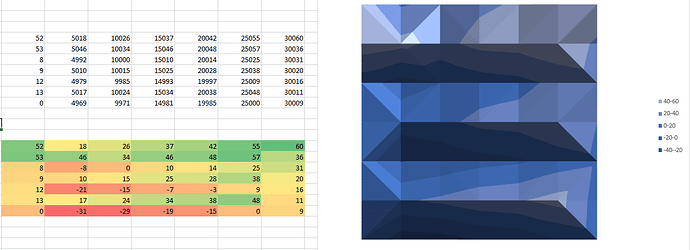
which got me a matrix of actual positions reached, and then a map of the relative errors (unit = 1/100th of mm in the colourful part):
So basically between -0.3mm and +0.5mm error. Which is way more than the intrinsic precision that I know my machine has (I recently cut a piece within 0.05mm of its expected dimension), so there you go, I’m looking at the mechanical error of my jig (which is not surprising, this quick and dirty prototype was aligned/assembled by hand, is probably not quite square, and has some play where the router joins the DRO (I used an old/worthless chinesium V-bit to center the router into one hole of the metal plate attached to the DRO display…)
So next steps: a better mechanical setup, and a custom made piece for attaching a 6mm stud to the DRO with no play. Then repeatability tests, and manual/calibrated checks to map the error of the jig, before mapping the errors of the Shapeoko.
