Cycle start(resume) is another grbl command. Default is a ~, but can be a hardware switch as well.
Edited my poorly ended previous reply to include the quote.
Something in addition to my step #7 is required to resume cutting?
Nope. Feedhold has to be released and cycle start has to be sent.
Again, I’m not sure how this works in CM, but @Julien explained his revelation above.
2 Likes
Maybe @Julien can clarify what CM does. What advantage(s) does a hardware “cycle start” offer?
A physical button. Convenience. Probably make it green, maybe with LEDs.
Not really, I can only observe and note that when one hits “Start” after pause, GRBL receives a resume/“~” command because it does the resume moves as programmed in GRBL.
And from @Vince.Fab’s observation we also concluded that it checks for a second occurrence of FH being triggered, and executes the same resume routine if this happens.
About how tough/useful might you think it would it be to connect a lil ol Arduino with sound/vibration sensors to trigger an automatic feedhold?
Crashing sounds and feels much different than smooth operating, shouldn’t be too hard. Also +14 cool points
4 Likes
No no no no, don’t do that (triggering me to start yet another wild experiment  )
)
Actually I think that would be quite easy and for a first try I would remove the arduino from the picture:
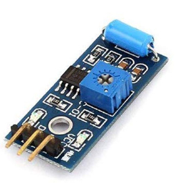
- I would get one of those vibration sensors that have a potentiometer to adjust the level above which they generate an alarm signal,
connect that output signal to a relay module,
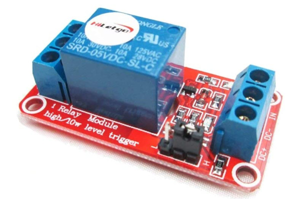
and connect the relay output such that when activated it shorts the two feedhold pins, and voila.
That’s the naive approach, and it might not be easy to set that potentiometer such that it triggers at the right level of vibration and never false-triggers, if that doesn’t work reliably enough the next step would be to put the arduino back into the picture, and interface it with an accelerometer, some of them have quite fancy built-in filters and can generate an alarm above a given threshold again, or you might even go so far as so read the accelerometer at a defined sample rate and perform custom data processing on it. But that, is another story.
EDIT: or, go full crazy and hook up an IMU to the arduino as you posted 
And while I was writing this, a vibration sensor module appeared in my Amazon basket and an order was placed. I’m weak.
6 Likes
" We are the Borg. You will be assimilated. Resistance is futile. "
3 Likes
I think the first step for vibration/crash detection feed hold would be to have a reference waveform from a crash so you could know what frequencies and magnitudes were different from normal operation. Unfortunately I doubt many people 1) have vibration monitoring already and 2) want to intentionally crash their machine to generate this data set.
If it’s possible to identify the crash event from frequency and not magnitude, it might be possible to do using machine learning. There are plenty of videos online of people crashing their machines and if you could teach a computer to identify those sounds, you would then be able to do the same on your machine with simply a microphone.
1 Like
Yep, training data is what I was thinking too. You’d need both crash and normal running labelled training data sets unless manual analysis can extract key signatures of ‘crash’ operation.
The problem with frequency domain analysis is that there are many different cutters being used at different speeds and also resonances and vibrations in the machine and workpiece which would be hard to unpick.
Arguably there is some level of vibration amplitude that is ‘excess’ that an acceleromter with sufficient high frequency bandwidth (probably not your normal IMU which can’t sample often enough but a vibration sensor with either sufficient sampling rate or onboard analysis like some of the Bosch units) mounted to the spindle mount could detect and throw a warning that the machine vibration & deflection is now outside of your preferred boundary, be that a crash or just an over-optimistic toolpath.
“Crash detection” was one of the possible outcomes of monitoring the cutting torque of the AC VFD spindles or DC BLDC spindle in the Brushless Makita thread. In many cases a machine ‘crash’ will correspond to excess cutter engagment and a spike in torque.
The questions underneath this though (from data analysis on larger machinery) are;
- What do we consider a ‘crash’ event to be? We’d need a requirement list of events we plan to detect and then try to match detection mechanisms to those events
- What is the time frame we have to detect and respond to such an event? In many cases the spindle spindown time is going to be longer than the event duration
- What action(s) do we want to take when a crash happens? (rapid retract of Z?)
I’ve been watching the VFD current whilst cutting with my 2.2kW spindle, it’s had a couple of, shall we say, unplanned events, including running through an aluminium clamp with a chamfer bit. The problem with the big spindle is that the excess power compared to a reasonable cutting load on the Shapeoko means that the crashes are largely self-clearing as the spindle chews up whatever was in the way. It’s hard to see any load change on the slowly updating VFD display which only updates a couple of times a second, peak cutting loads have frequently come and gone before any update.
So there’s vibration analysis from the spindle mount and detected motor torque (current as @gmack has spent a lot of time working out expected sensible numbers for) as inputs.
As for outputs, in the event of a crash we might want to do something more urgent than the feed hold action, if we were plugging into an alternative gcode sender a rapid Z retract might be the least worst automated option?
3 Likes
You could just change the parking motion to be rapid.
The sensor @Julien is looking at (waiting for?) just has a digital out with a little trimpot to adjust the threshold. Finding the “crash” setting would be the trick.
Or…you could go the direction of @LiamN and eventually land on some sort of multiple thermal image capable cameras feeding data to an AI system that will handle the crash, adjust the job, and order you some new endmills based on its analysis. Then it’ll tell you that the sign you made for your mom’s bathroom really wasn’t worth all the effort when the lady down the street has a Cricut and just stenciled the same thing. Looks more Pintresty than the V-carve inlay anyway.
5 Likes
C’mon Neil, we’re trying to overthink the problem over here 
In reality, the best thing to do is either baby sit your machine while it’s cutting (do other stuff in the shop) or broadcast the video/audio over your network and do your babysitting remotely. However, it’s interesting to think about how to automate this kind of task (isn’t that why we’re all here instead of just getting out our saws and chisels?).
3 Likes
Wouldn’t rapid feed hold (reportedly already done in the hardware/firmware) be sufficient? Multiple devices with normally open switch/relay contacts and/or open collectors/drains could be connected in parallel to the inputs. Opto couplers could also be used if necessary for ground isolation.
I’m with ya! Believe me, when I saw how people were handling their vacuum hoses, my first thought was to split step and direction signals to a lightweight machine suspended above just to move the hose around.
![]()
2 Likes
Yes, quite likely, I haven’t tried the feed hold yet, got some Molex connectors on order.
I was more raising a set of questions about the requirements and what people would like to see as an outcome rather than trying to specify anything, shake out what the available options are etc. It’s also good to be realistic about what we think any engineered solution might actually be able to prevent and whether it’s worth the complexity.
As for the sensor comments, I’ve been down the accellerometer route before and just relaying the problems we saw with low polling frequency sensors. Vibration analysis is a very common approach in industrial systems but the cellphone type IMUs generally don’t make good vibration sensors as they’re designed to give consistent readings despite vibration, as with all things your mileage may vary.
If there’s something simple we can do with COTS hardware like that integrated vibration sensor module that might be great, but we’ll only find out by trying. I’ve still got the various sensor parts on order for the VFD power measurements, yet to see if I get anything useful out of that.
3 Likes
Be careful with using this feature! I just had a crash where when the program was feed held and resumed, but instead of continuing it’s move at retraction height, it went to working height and ran the end mill through my part. This may have just been bad luck that I caught it right between moves and something got lost in the g-code sender, but please note that this feature really is intended to be a FEED HOLD, not a program pause and resume function (again, caveat, with CNCJS).
@Kai Really? I’ve used it for a couple years and I’ve never seen that happen. Was that the first feedhold? Stock grbl settings?
Yep. I tested the feed hold running air cuts a bunch of times and then tested it while cutting parts a few times today and didn’t have any issues until the crash. Didn’t break anything luckily, but I took a full diameter width 7mm depth cut unintentionally. I went back and checked the tool paths in Fusion and it was not supposed to do this.

1 Like
Yikes. Any guesses? Think it was a communication issue?