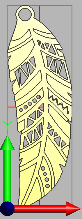
I am trying to make some earrings for my wife’s birthday. It is a two-sided design, so I would need to flip over to mill the second side. The stock will be 1/16" brass. I have the Nomad Flip Jig, but it seems to really be designed for thicker material. Any suggestion on how to best do the work holding? I am thinking I might need to buy the low profile vise but before I spend for that I wanted to check here. Also, all the flip jig example videos I see are for designs which are symmetrical around at least one axis. Will Meshcam’s flip job setting handle this OK?
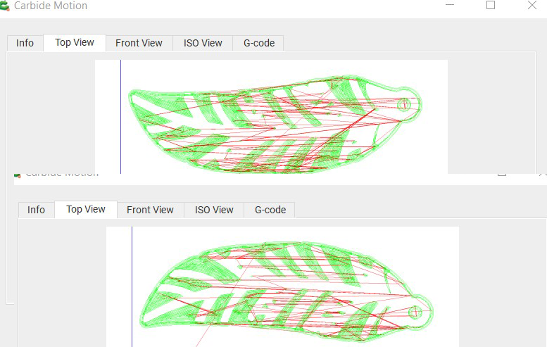
I updated Carbide Motion so I could see the preview (very handy) and it seems like it is flipping the design appropriately so when I flip the design is reversed. How about the work holding to flip something so thin (1/16’ brass)?
yeah either milling a simple pocket to match the outline of the side you want to machine, or you’re adding two registration pin holes and tape/supergluing it down.
You already have two “registration” holes in the design. All you need is to add a pin for each existing hole for the flip side. You could also alter the design and add a larger hole for a pin in the pointed end.
Or you could leave a double “notch” for the pointed end while pocketing the rest of the fixture.
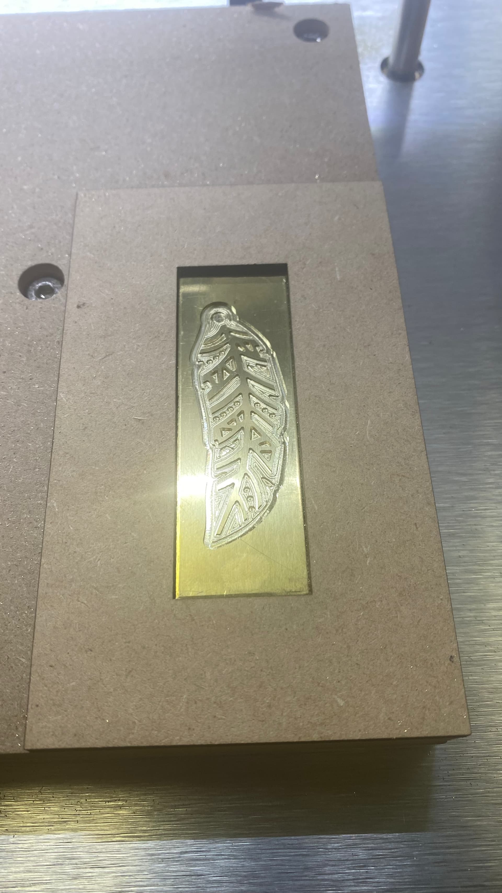
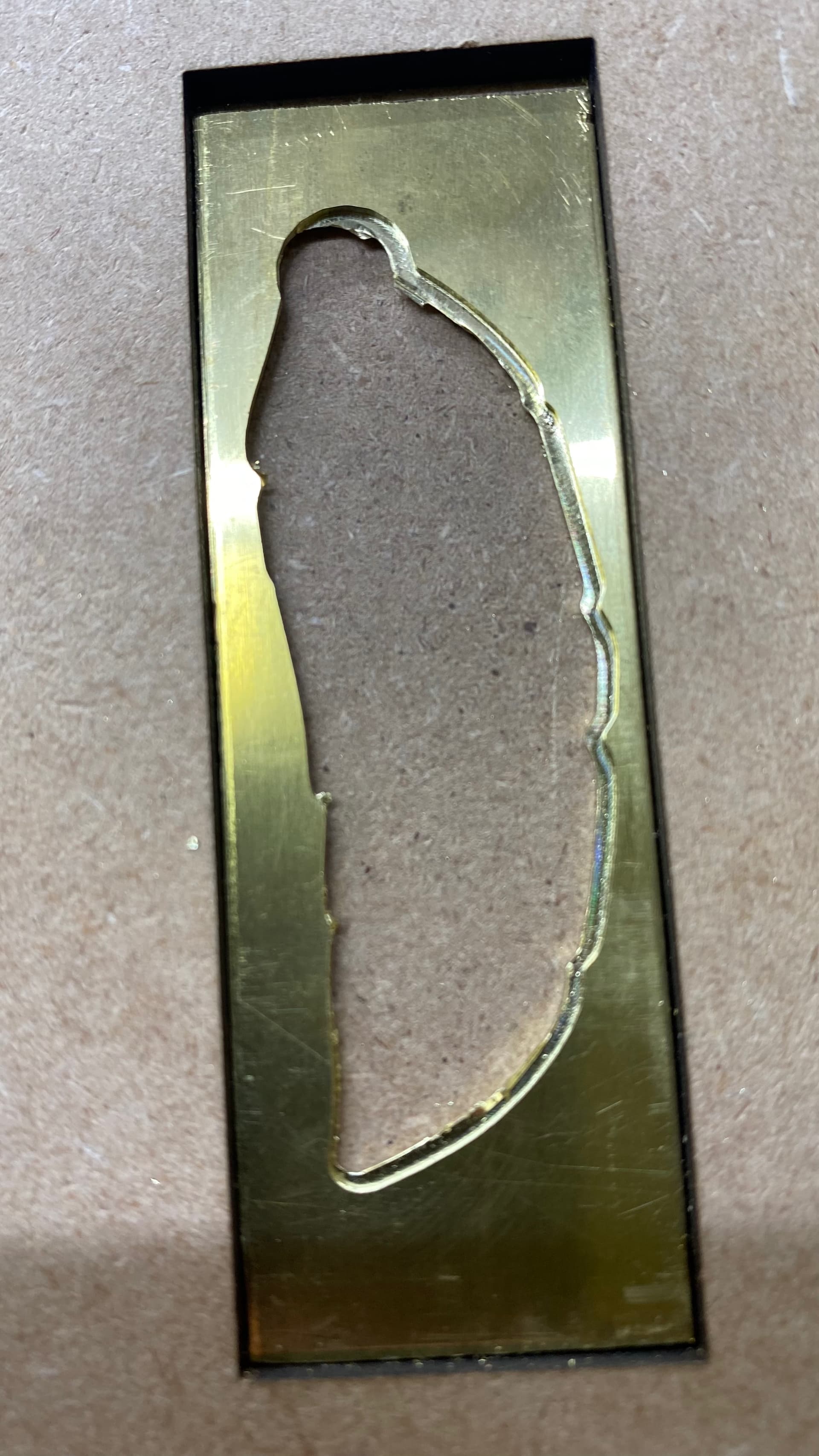
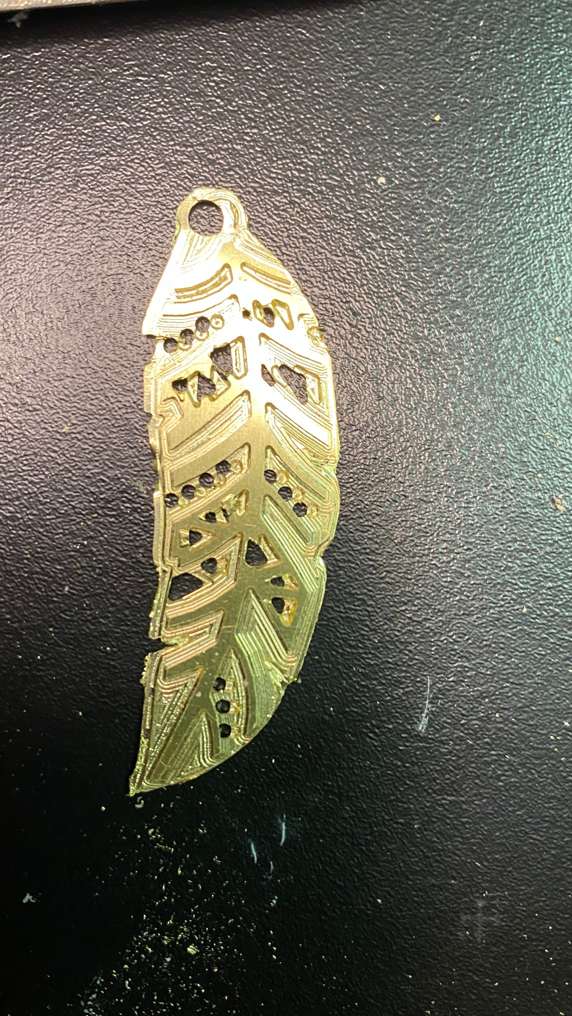
I created a fixture for the blank but the reverse seems to have been slightly off in the X. I used Fusion 360 CAM with the model centered in the stock in the X and Y and the fixture had no wiggle. Thoughts on what I might have done wrong? Now looking at the image it does not seem exactly centered in the blank when I milled the front side, not sure why that happened.
That means your old zero, assuming you flipped it around the Y axis (left to right), is now on the bottom right. Unless the stock exactly matches the design, there will be problems.
I think I would zero in the center, or bottom center, and take extra care finding the X center of your fixture. i.e. use an indicator, or flashlight/eyeball method, find both left & right sides & divide by 2 to get the center.
Or machine the pocket in the fixture from the center, don’t move it, then machine the part from the same center.
I selected “center” in Fusion 360 for X and Y, but because the model has no symmetry in either axis I’m not sure how it decides the center. Will look into that.
Thanks, I will give these a try. If I mill through the hole at the top of the design on the first side, could I also use the center of that hole as the starting point for milling the back?
You certainly could. However, if the hole is not on the centerline of the blank, you would be changing your zero after the flip. I think I would measure where the hole is in relation to the center zero, and use it as a check/adjustment.
So, if the hole is at X-0.1Y0.23 from the center, after the flip the hole should be at X0.1Y0.23 (the X sign flipped from negative to positive X)
The problem lies in the accuracy of the design vs the actual part / blank.
If you design the blank at exactly 1.000" wide, but then your blank is 1.020 wide, and you zero from the lower left corner, after the flip you will be 0.020 off.
If you cut from the center, but measure the center from one edge 0.500 over, you will still be off.
You need to set your zero as the actual center of the fixture/part. So, you pick up the left side & zero X. Then pick up the right side & note the X value. Then move half that value to find the center.
Now when you flip, the centerline of the part is still on center.
I have a job I’ll be doing soon that requires 5 setups. I will start by machining one side flat, and then profile 2 adjacent edges. The resulting corner will be my “J” corner. All the other setups will be measured from that same corner. So if my first setup is front-left-top of stock, after I flip the part my zero will be front-right-bottom of stock. And same for the other 3 setups, I’ll always zero from the same physical corner of the part. So, as long as I make sure I keep each setup square, all my dimensions should be right on.