This was previously discussed:
Doing that specific sort of joint in Carbide Create requires using unsupported tooling:
But if the joint is simplified, and one accepts voids:
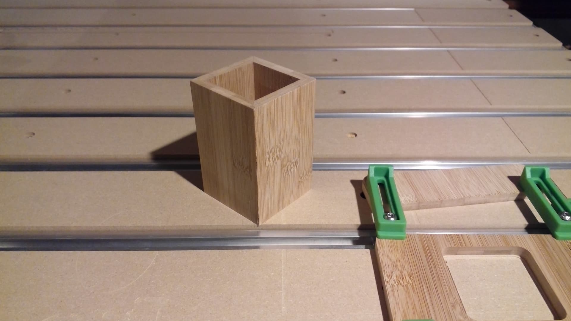
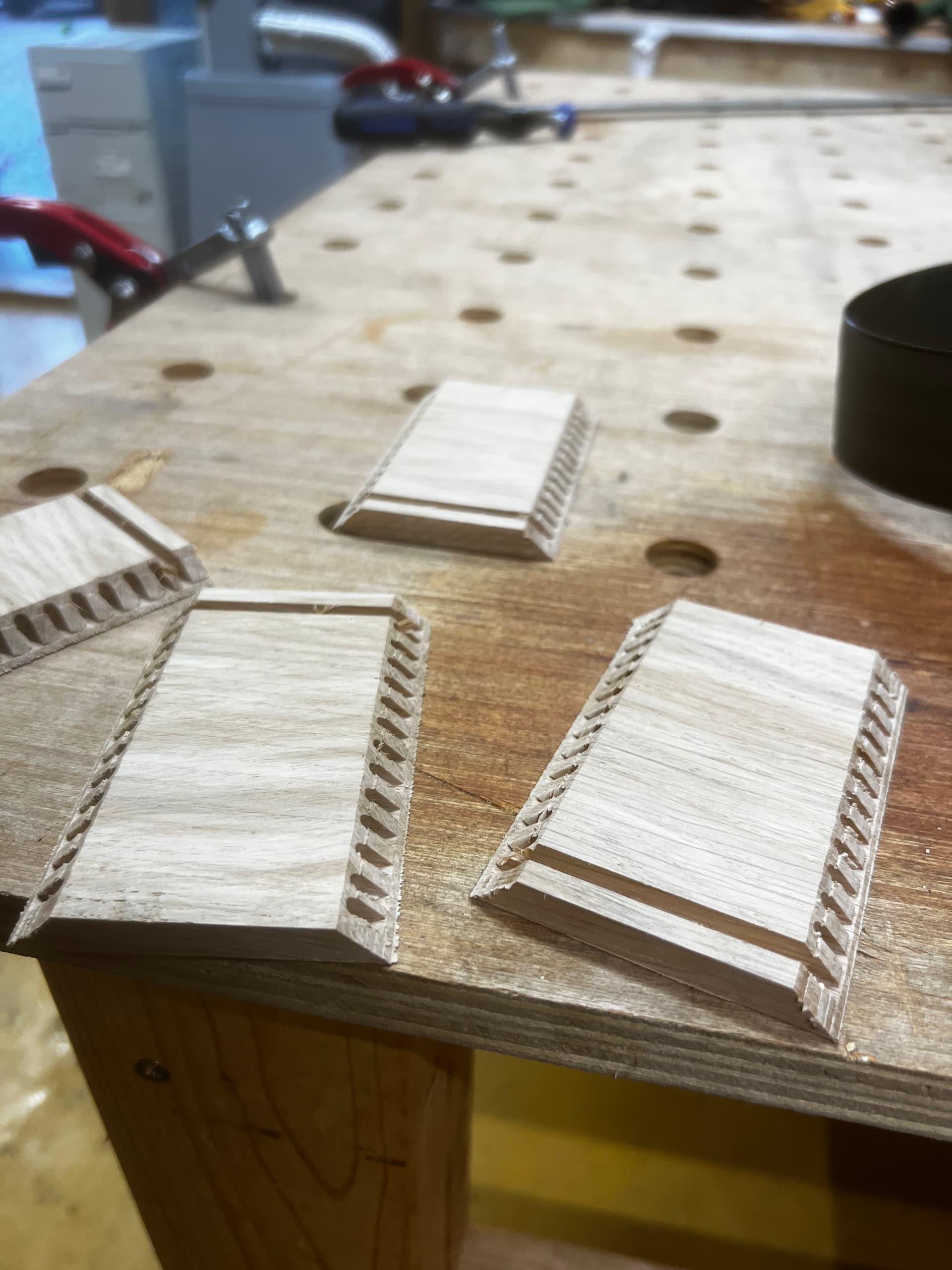
then one can cut parts:
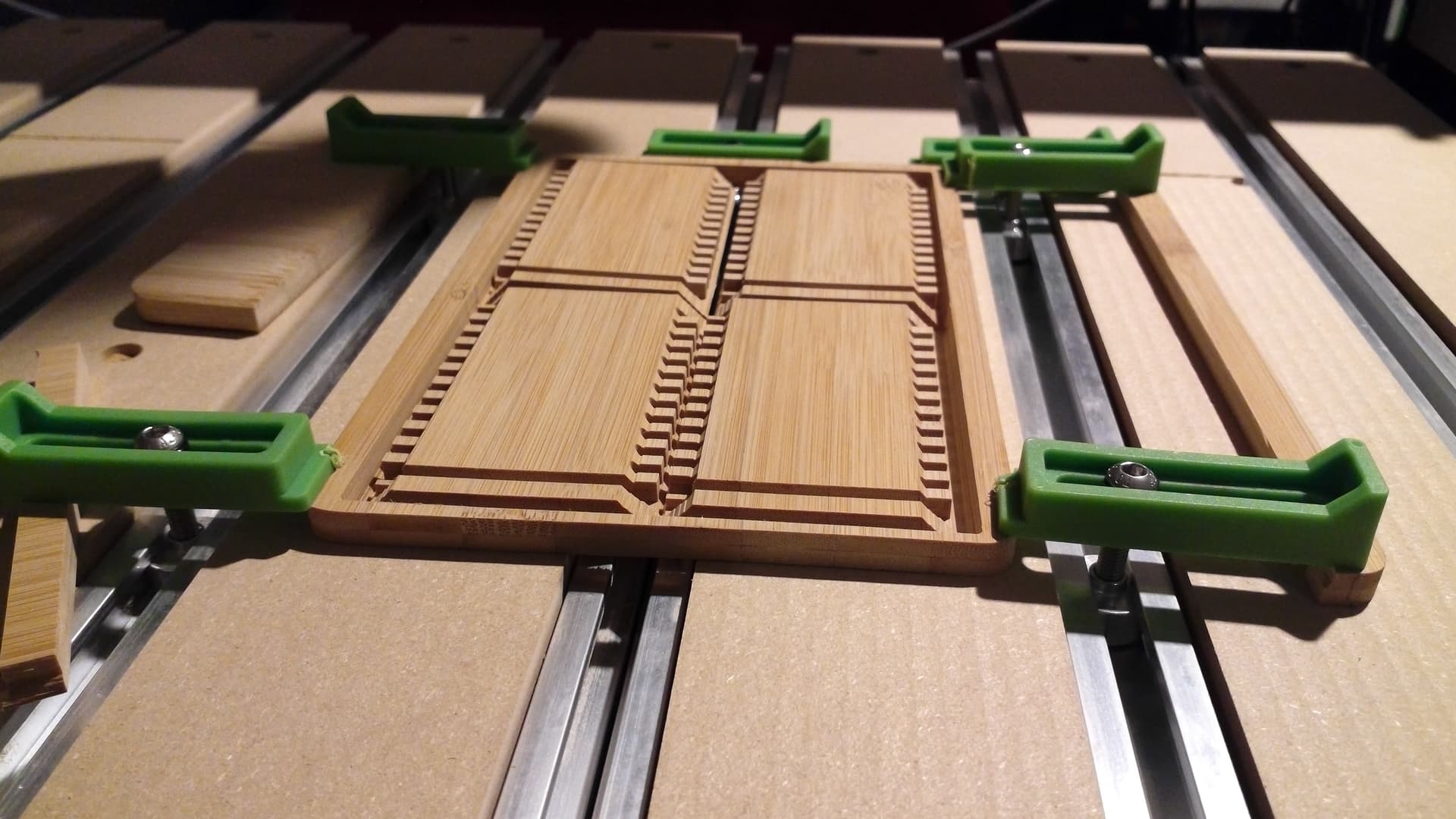
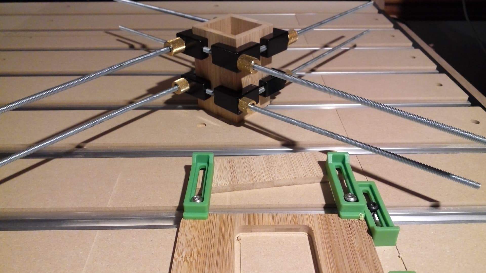
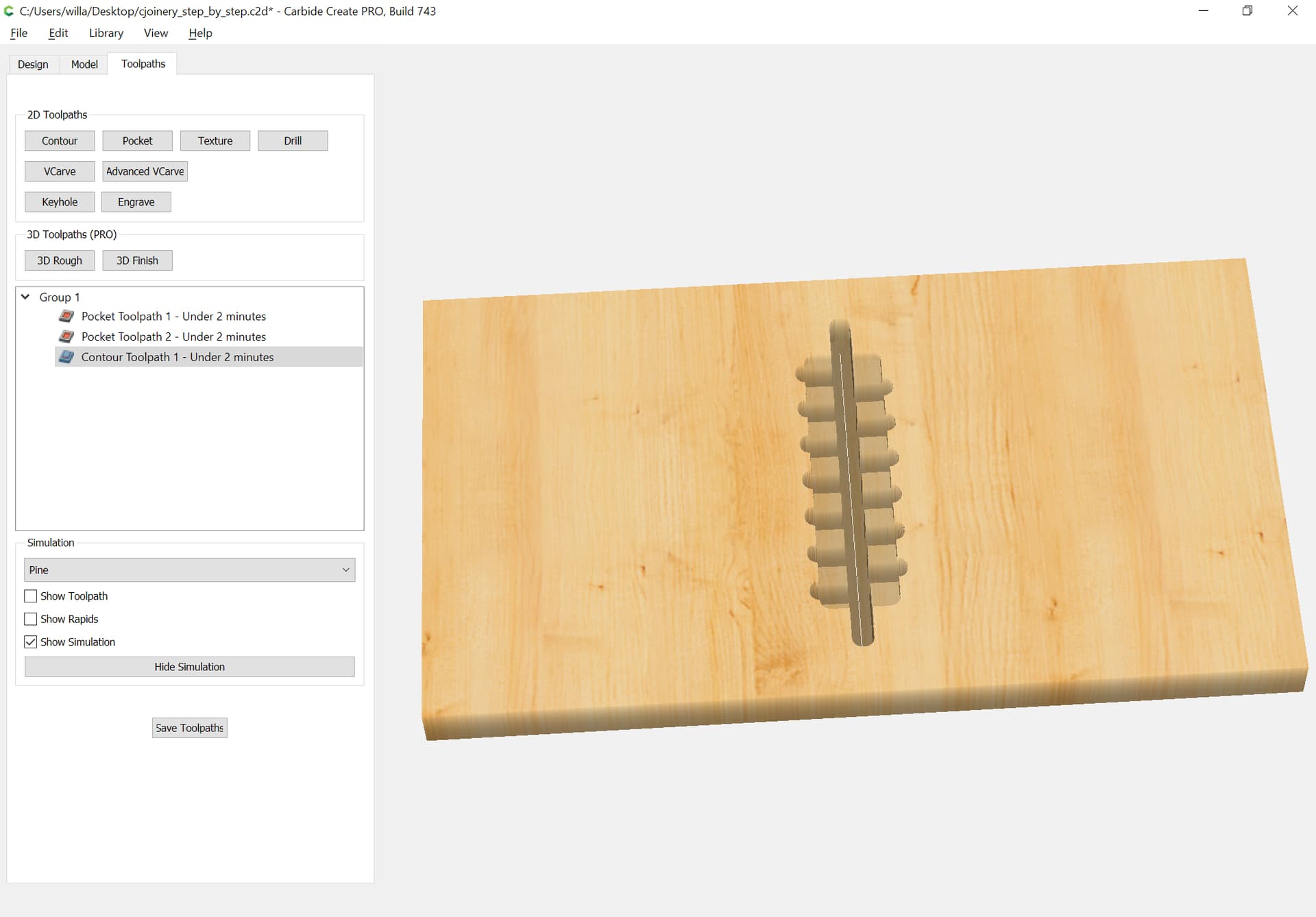
which fit together quite well:
This was previously discussed:
Doing that specific sort of joint in Carbide Create requires using unsupported tooling:
But if the joint is simplified, and one accepts voids:
then one can cut parts:
which fit together quite well:
Nice! I’d imagine the other benefit is that it’s probably way quicker to cut since it’s just 2d contours? I want to give this a shot in Fusion… I started on your other blind finger joints but didn’t end up getting it done yet because I got distracted trying to set up a parameters table
Cutting efficiency has been one of the reasons for the way I’ve been approaching this.
I’ve got the horizontal version modeled in BlockSCAD:
https://www.blockscad3d.com/community/projects/1478465
I’m probably going to try documenting laying things out manually here in a slightly simpler fashion, w/ a slight change to how the V is cut and a bit more space for the central channel (it is a really tight fit — it took quite a bit of force to separate the initial/dry fit when I disassembled it to install the bottom) — basically it’s the same as before, just no dogbones, shorter fingers, and the ends are V shaped instead.
Could you post a STEP file of the design you posted at the top? I’m trying to create it in Fusion and struggling with some of the finer details…
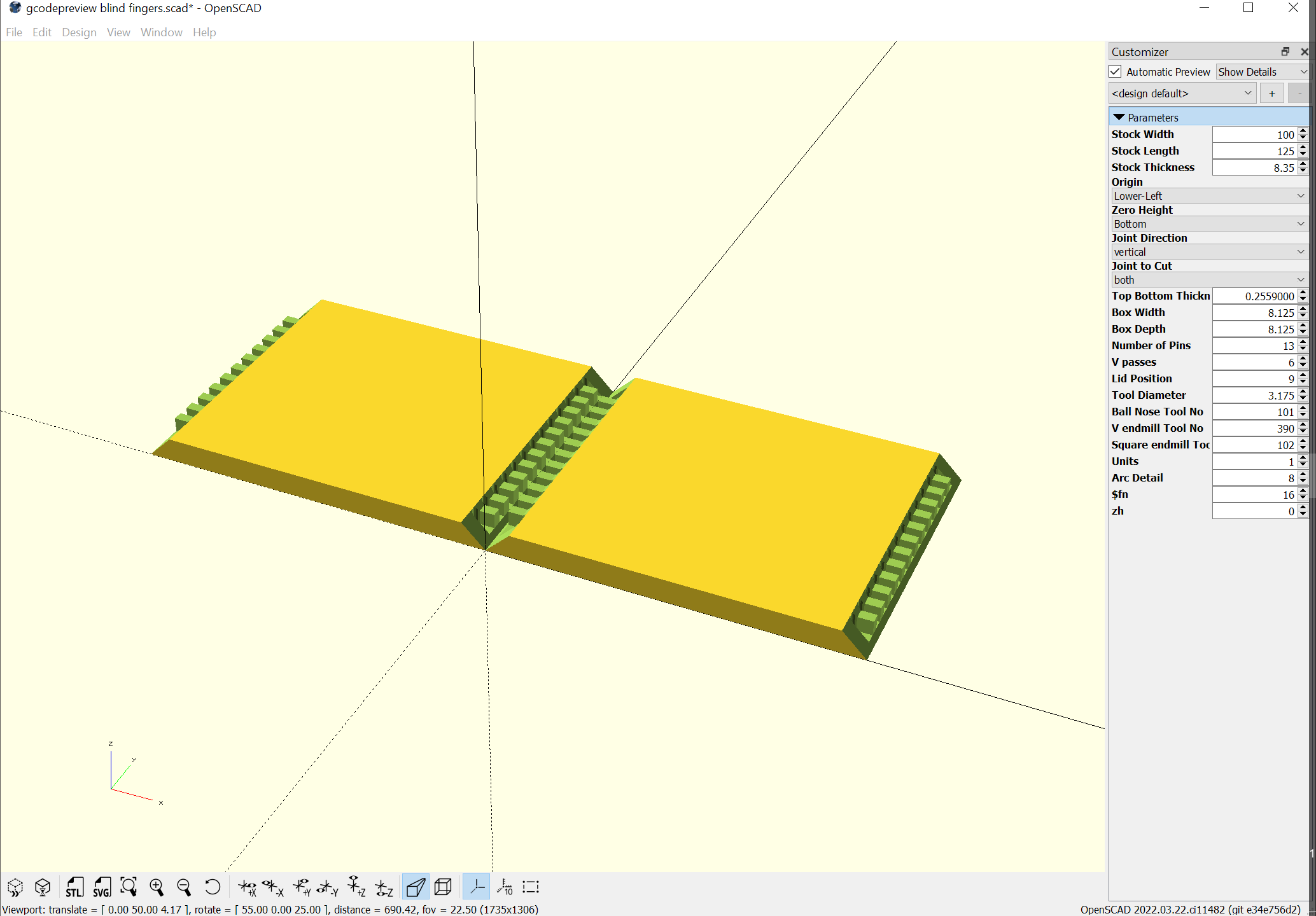
Here’s an STL:
gcodepreview blind fingers.stl (130.6 KB)
made from this .scad file:
gcodepreview blind fingers.zip (2.0 KB)
It’s not exactly the same as the .c2d file — need to cut the version from OpenSCAD yet.
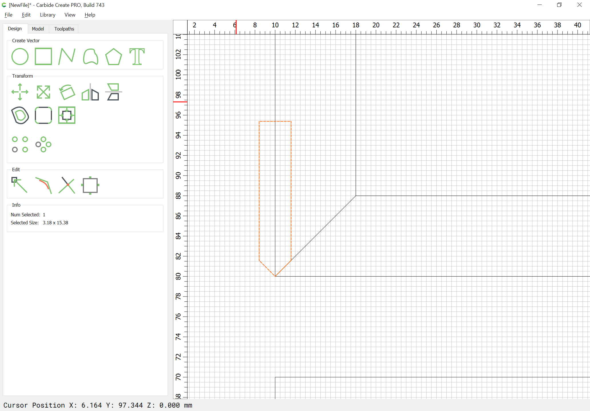
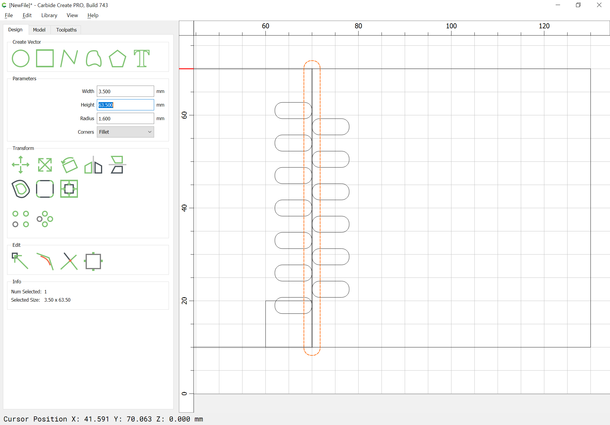
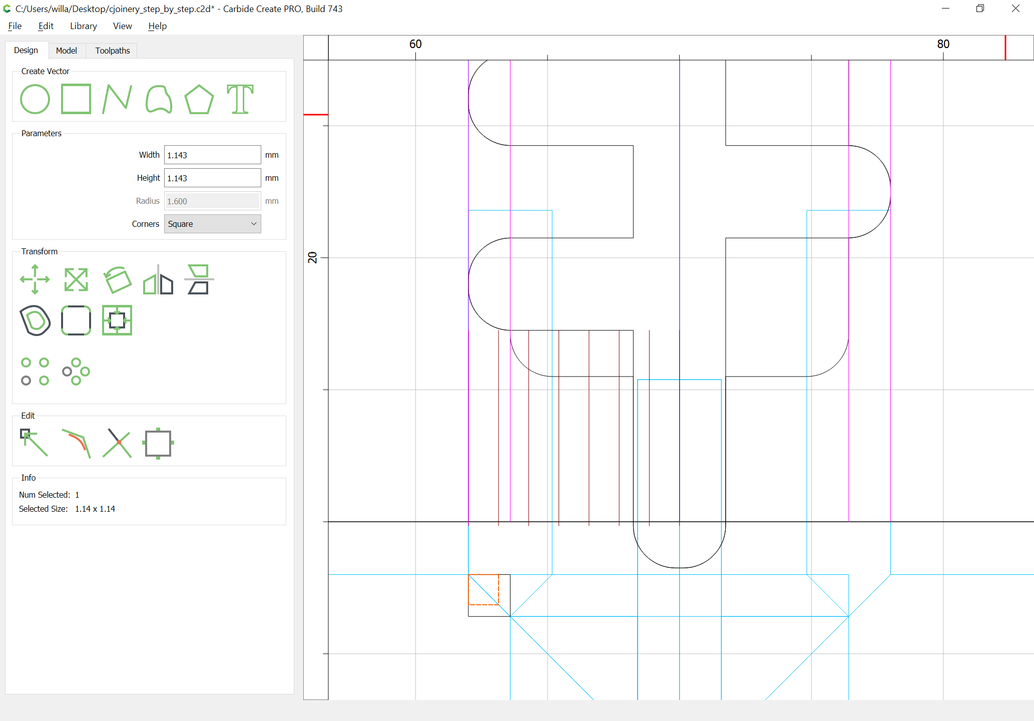
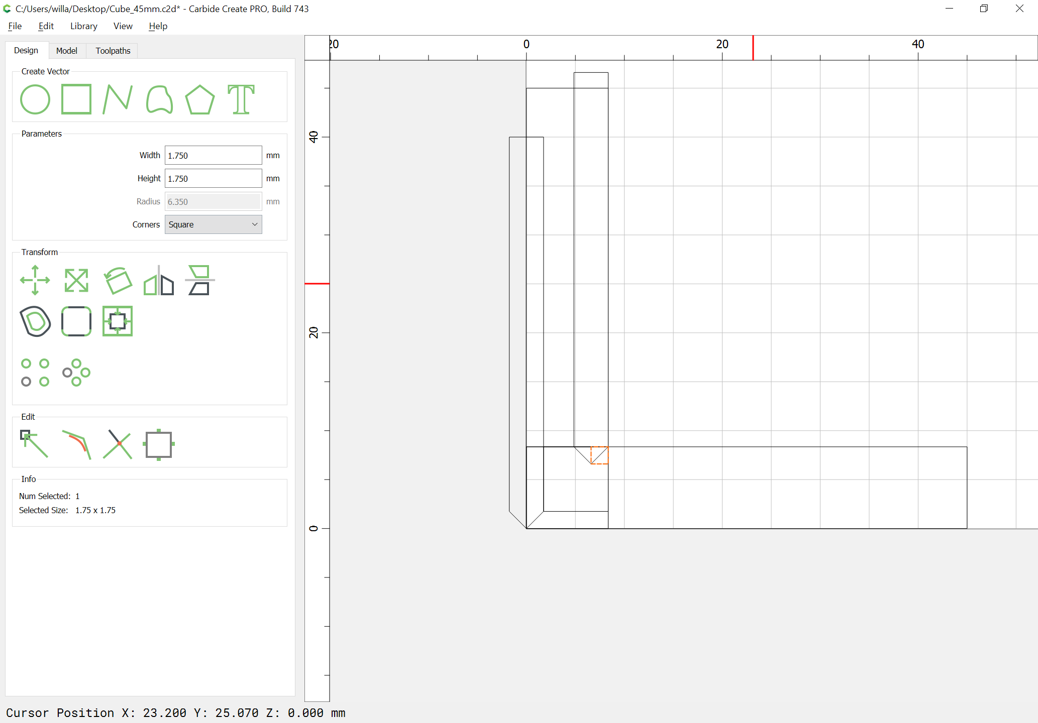
To make it step-by-step, as always, begin by drawing the joint and the V endmill up in profile:
and then draw in the fingers:
Then it should be simple to draw in the geometry for the fingers and replicate it as needed
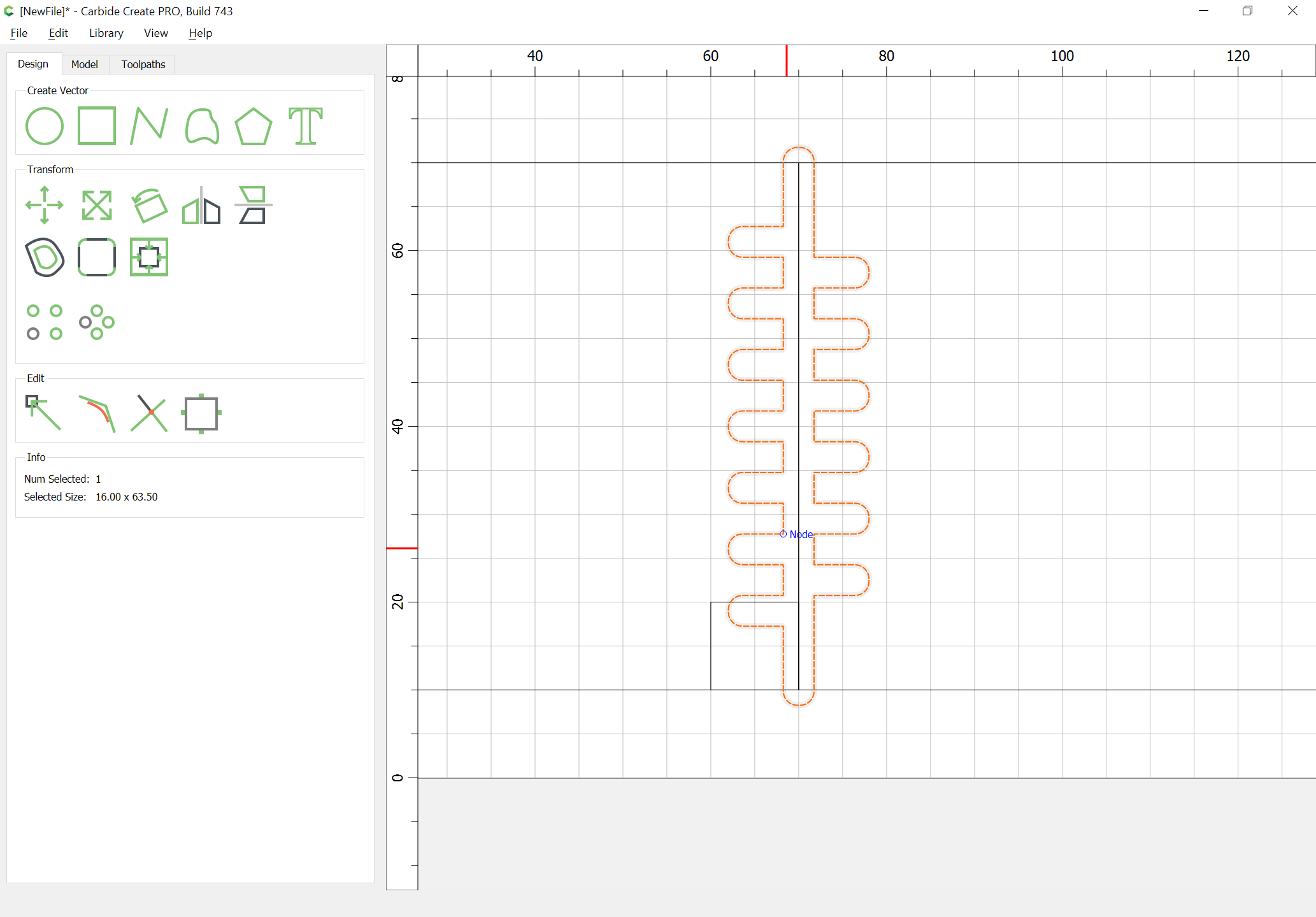
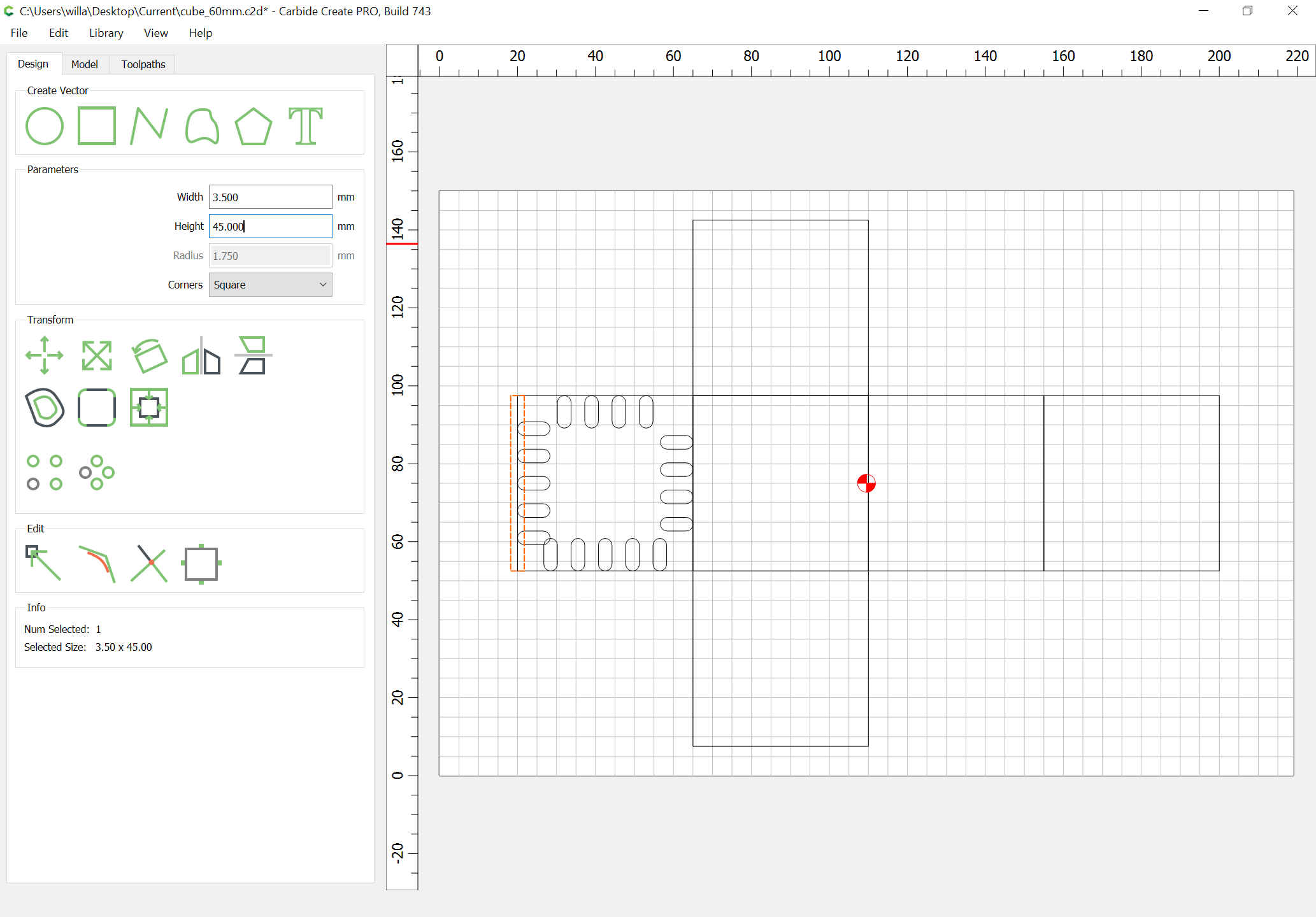
Draw in the fingerjoint/void geometry:
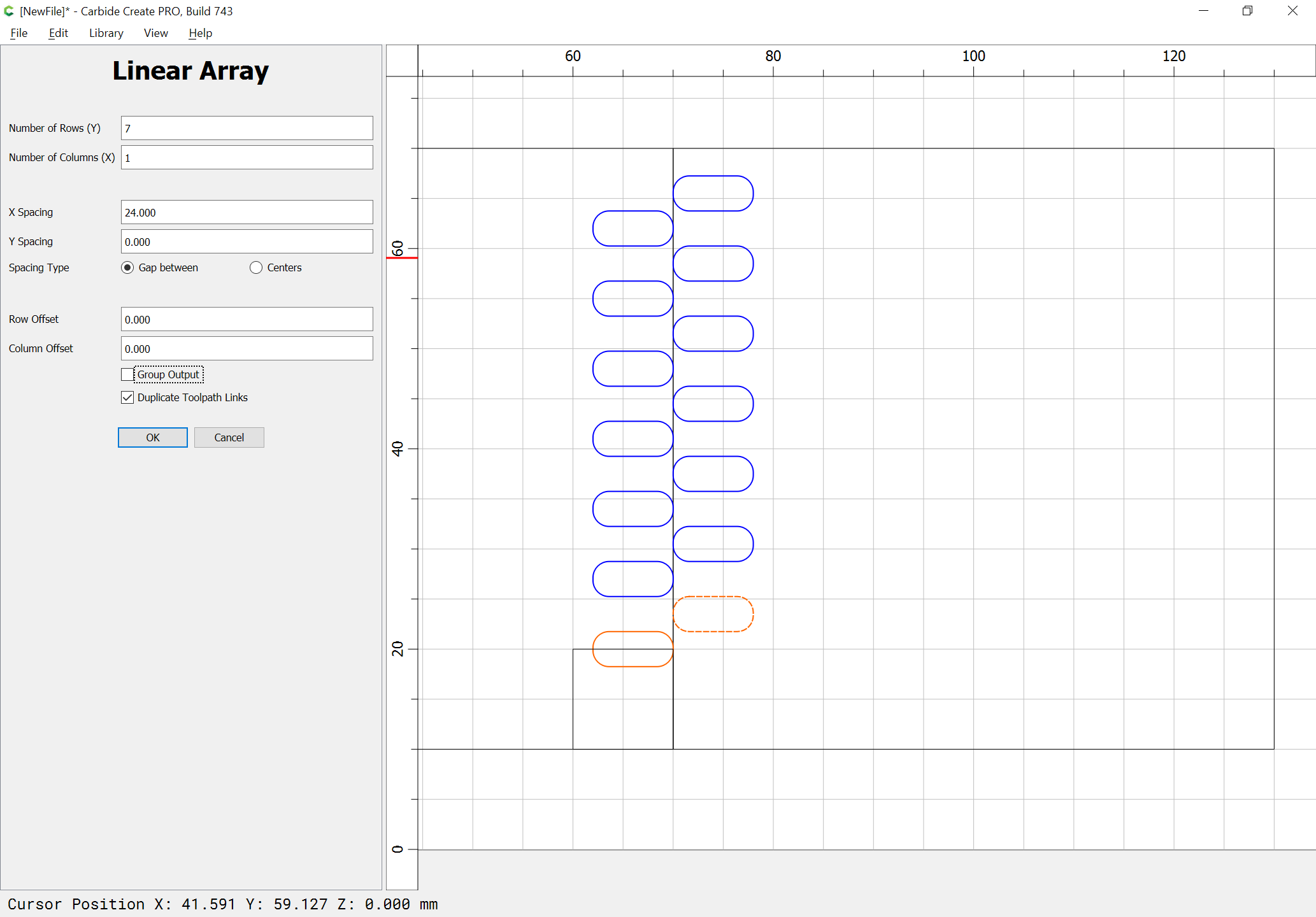
and then select a matching version offset vertically by the height so that they will be adjacent and then use Linear Array to duplicate it as needed:
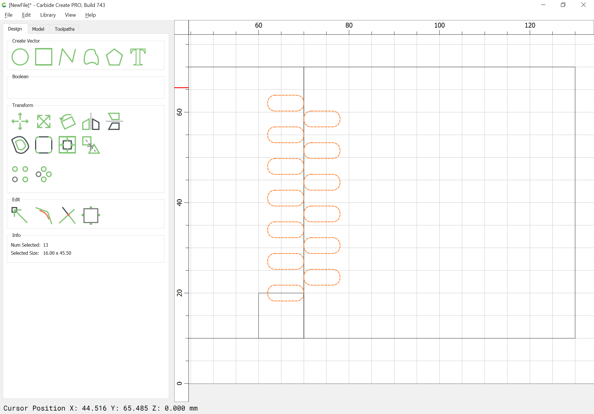
Delete the extra and group what is left:
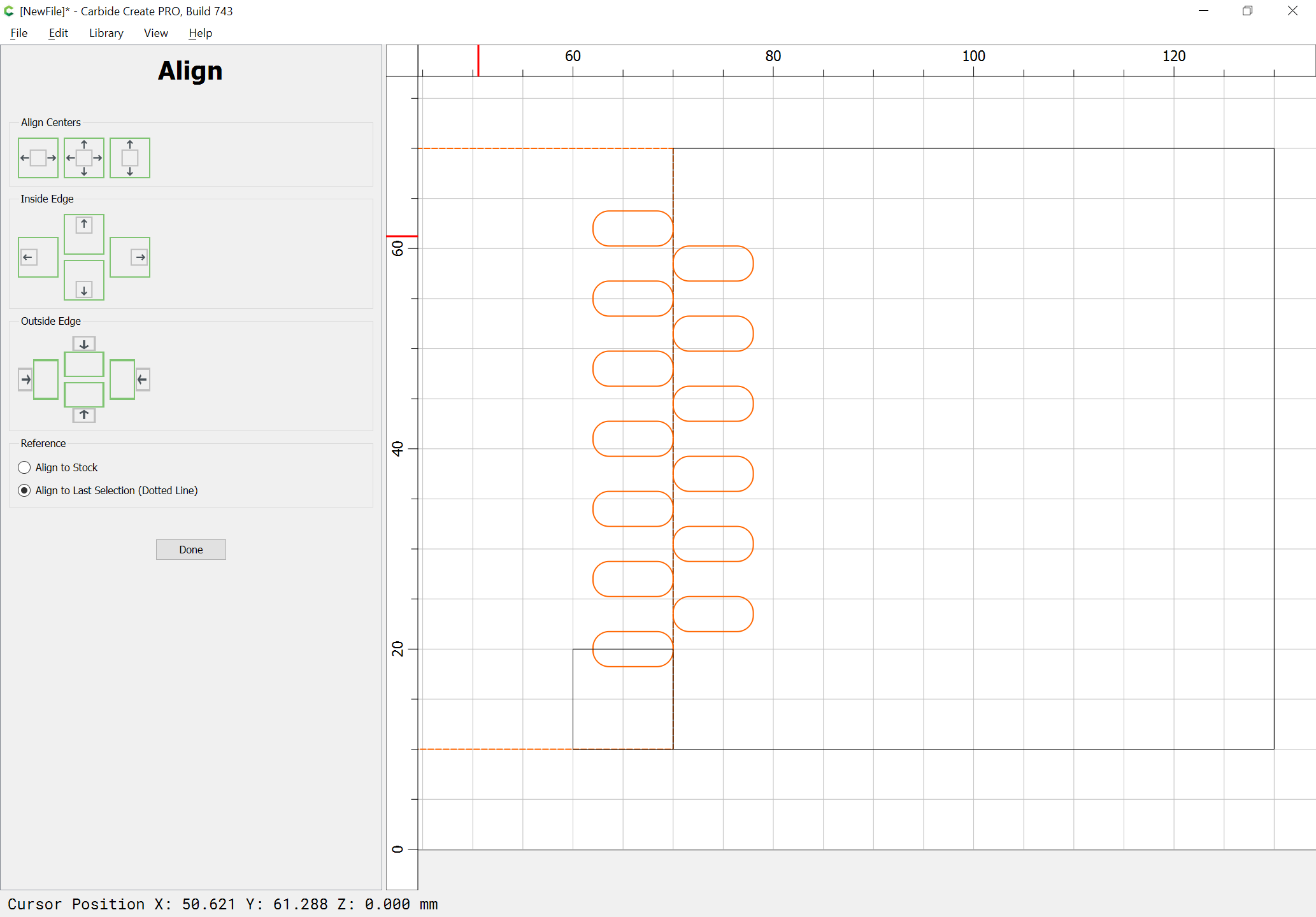
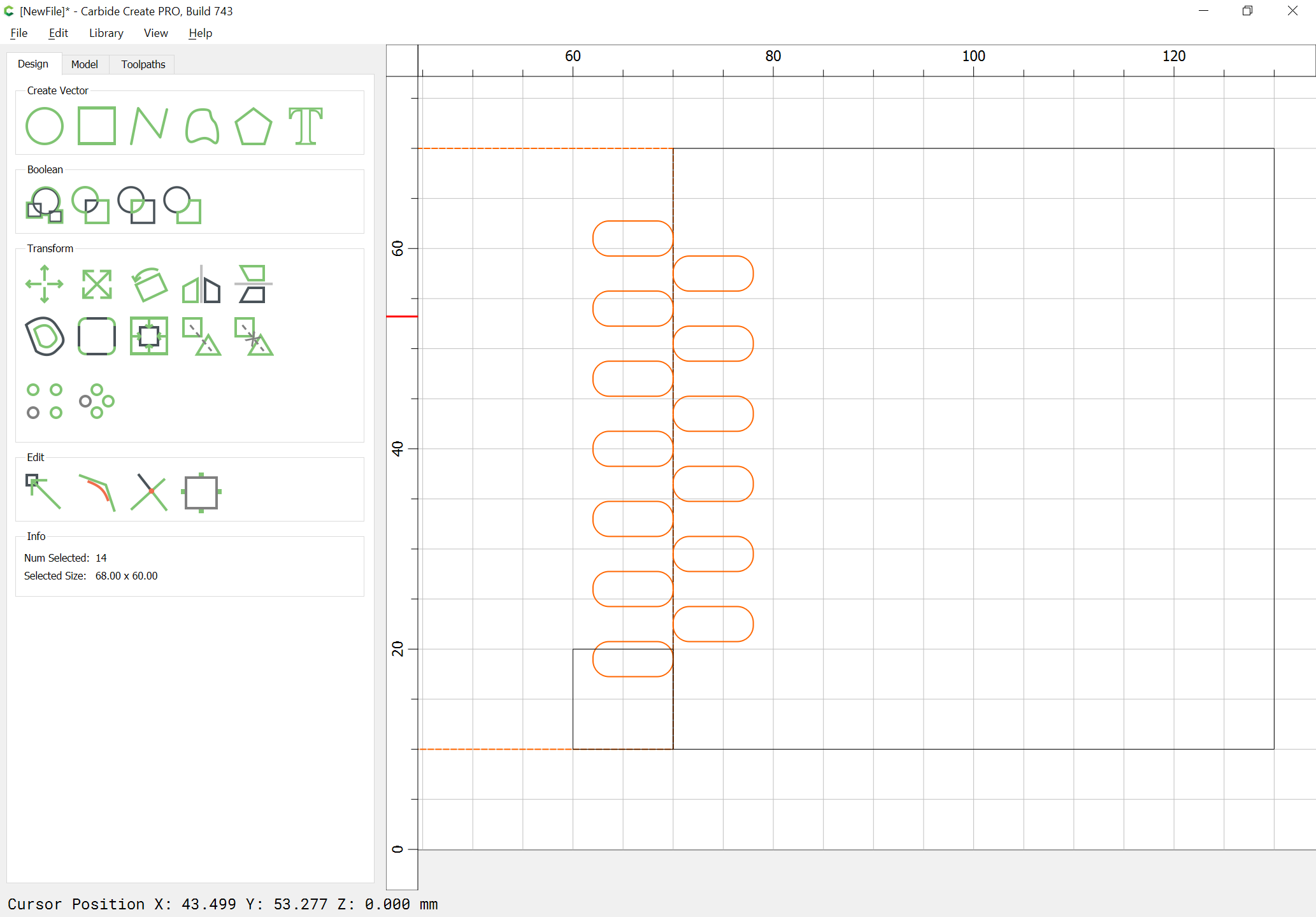
and vertically align it against the part outline:
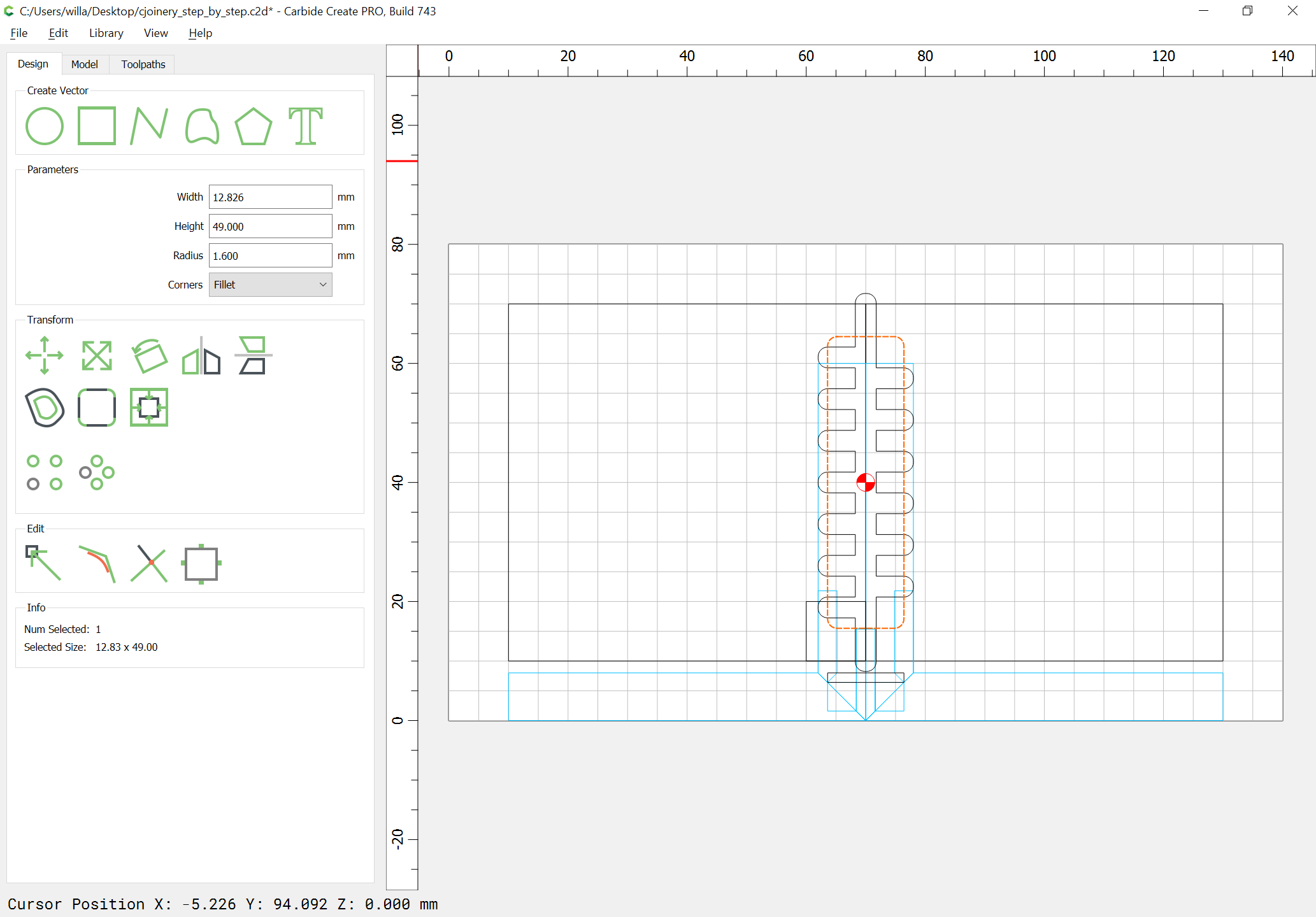
Then draw in a central channel:
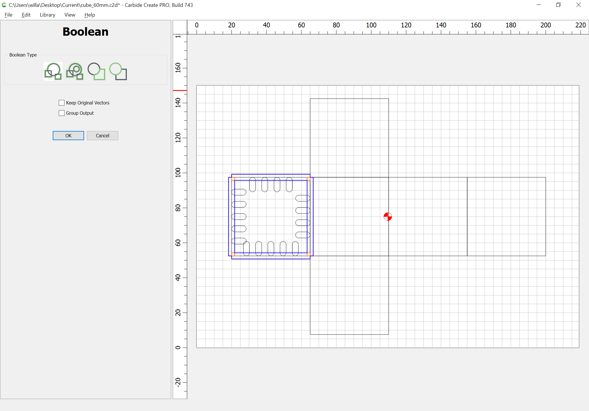
and then either Boolean union the joinery geometry or use Trim Vectors and Join Vector to create the necessary outline:
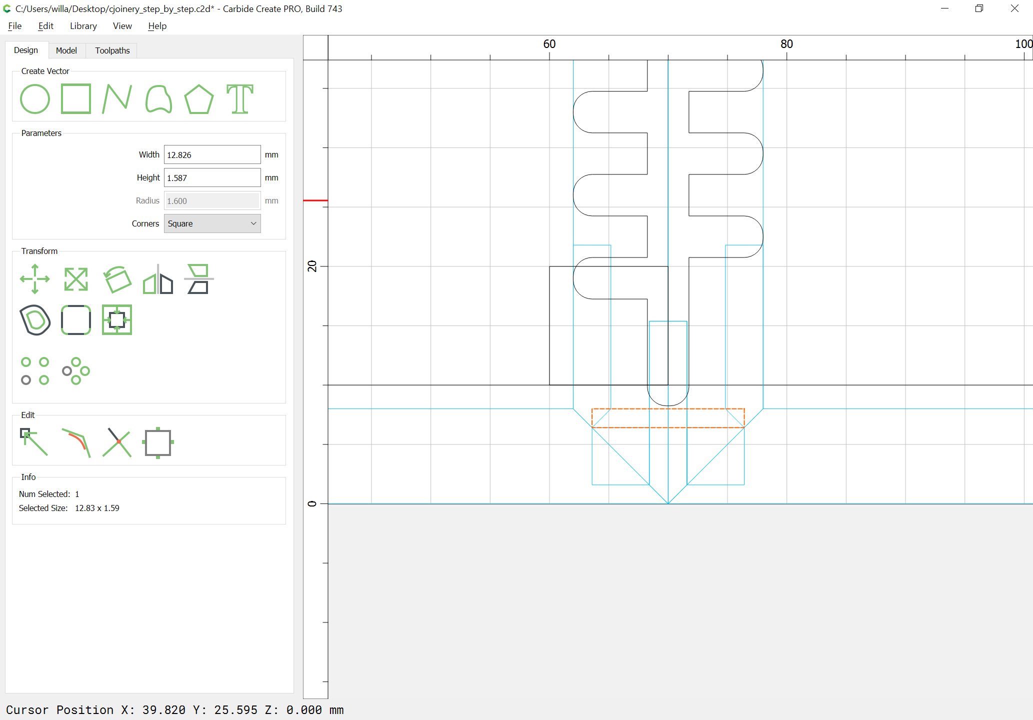
It will also be necessary to have a clearing pocket — check the profile view and draw in geometry to determine the needed width and depth:
Duplicate the joinery geometry and union it w/ a duplicate of the pocket clearing geometry:
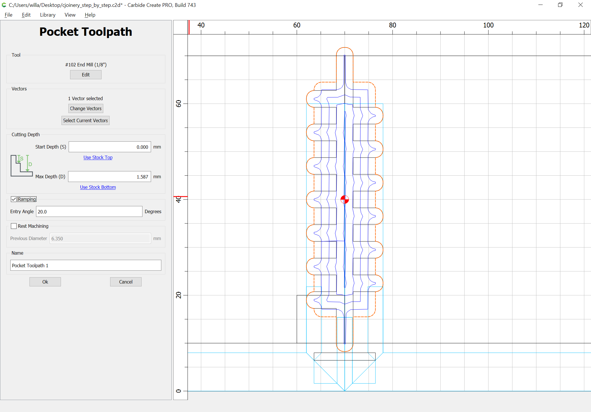
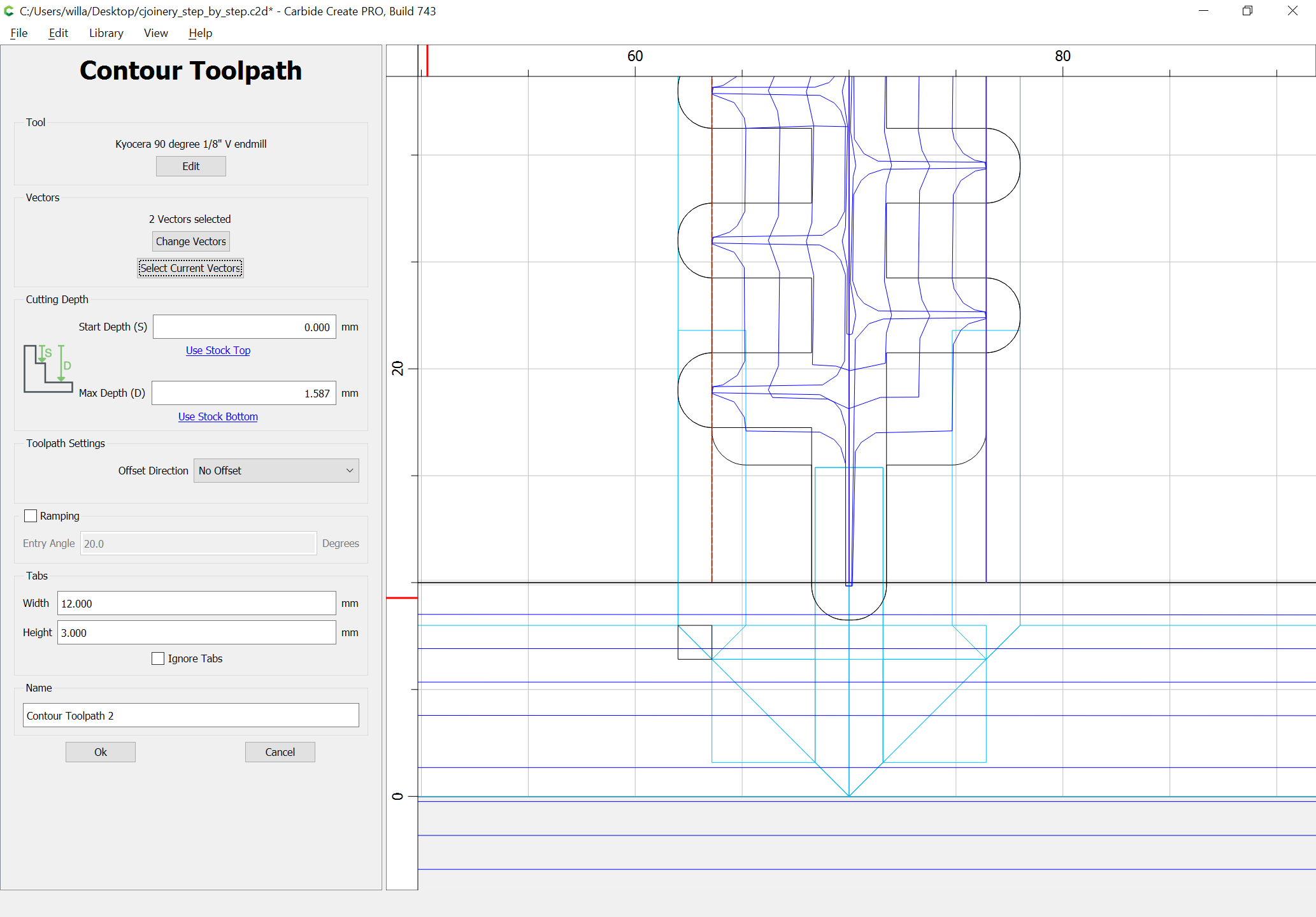
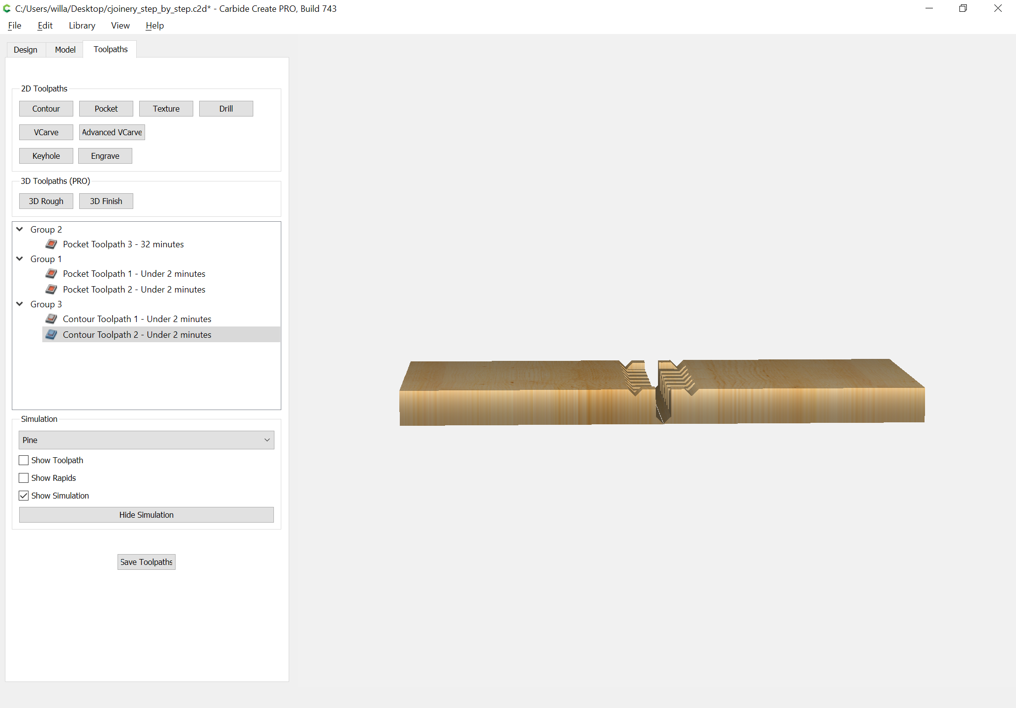
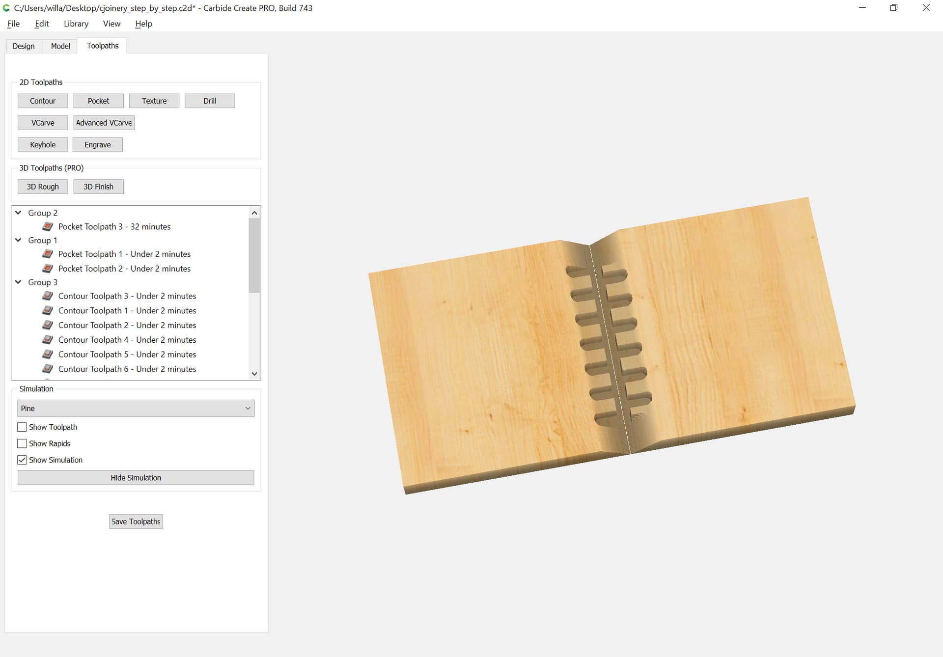
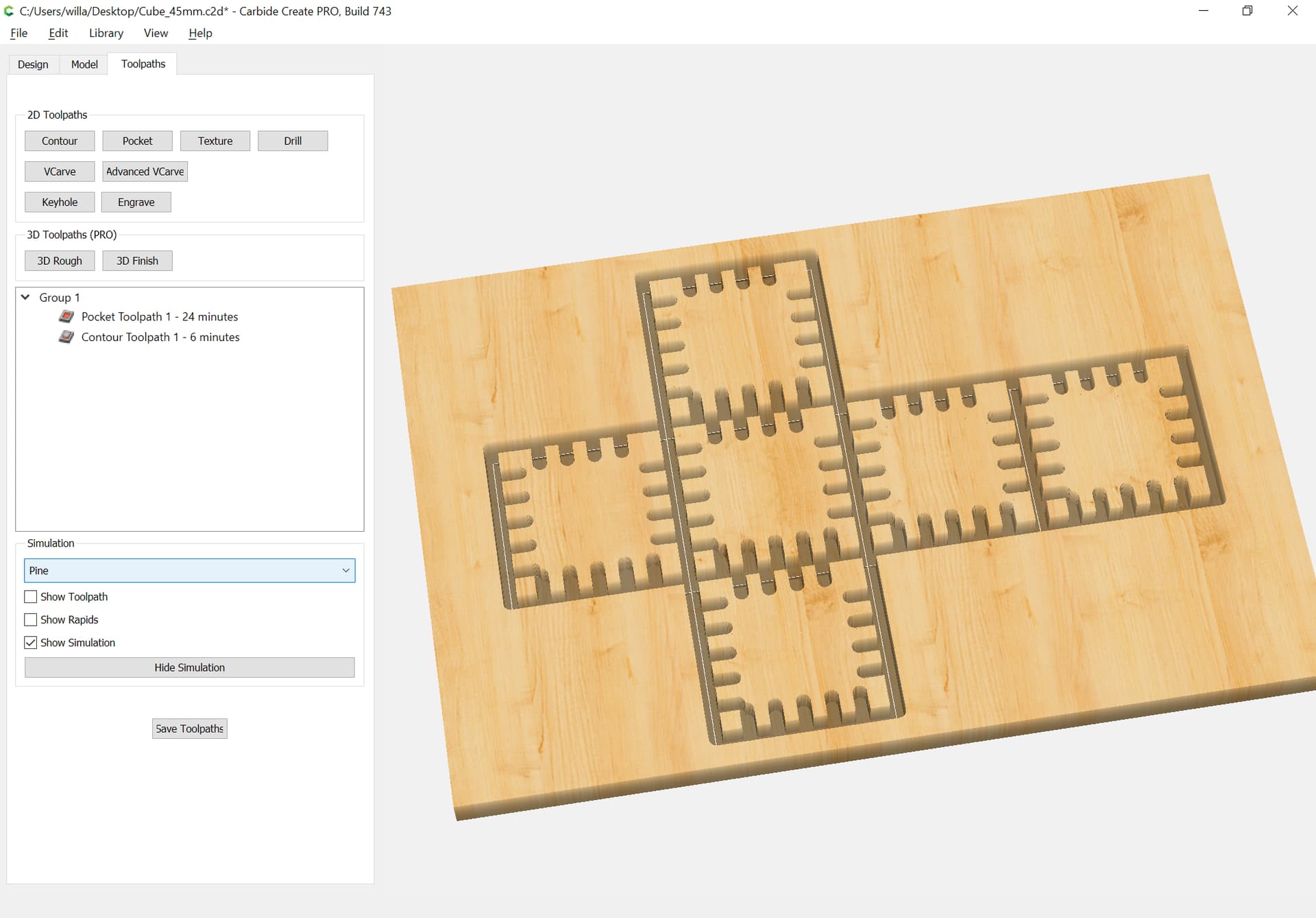
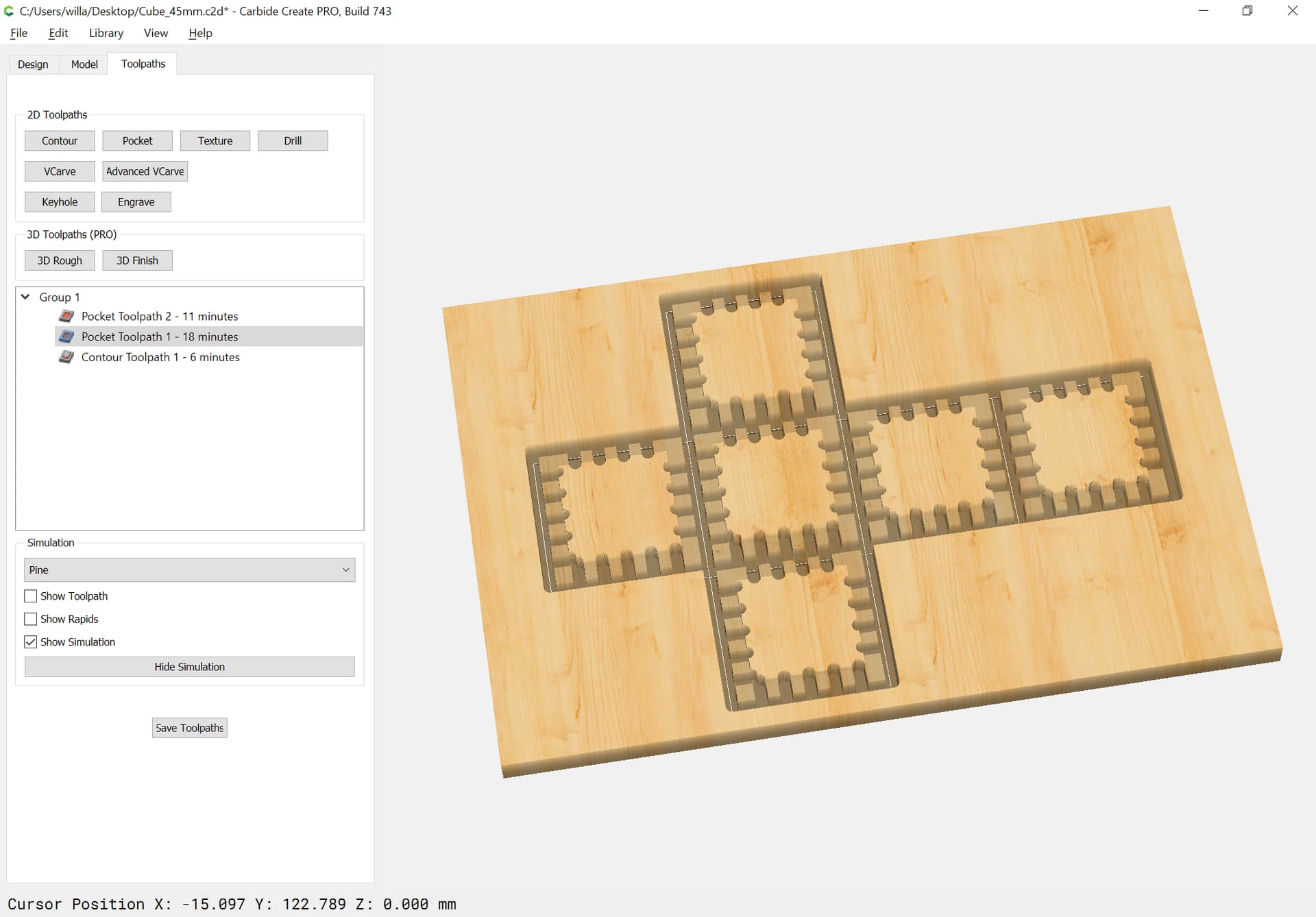
Assign toolpaths:
There will be two separate sets of V grooves:
One, at the bottom of the joint is obvious:
Or would be if the stock was the same size as the parts:
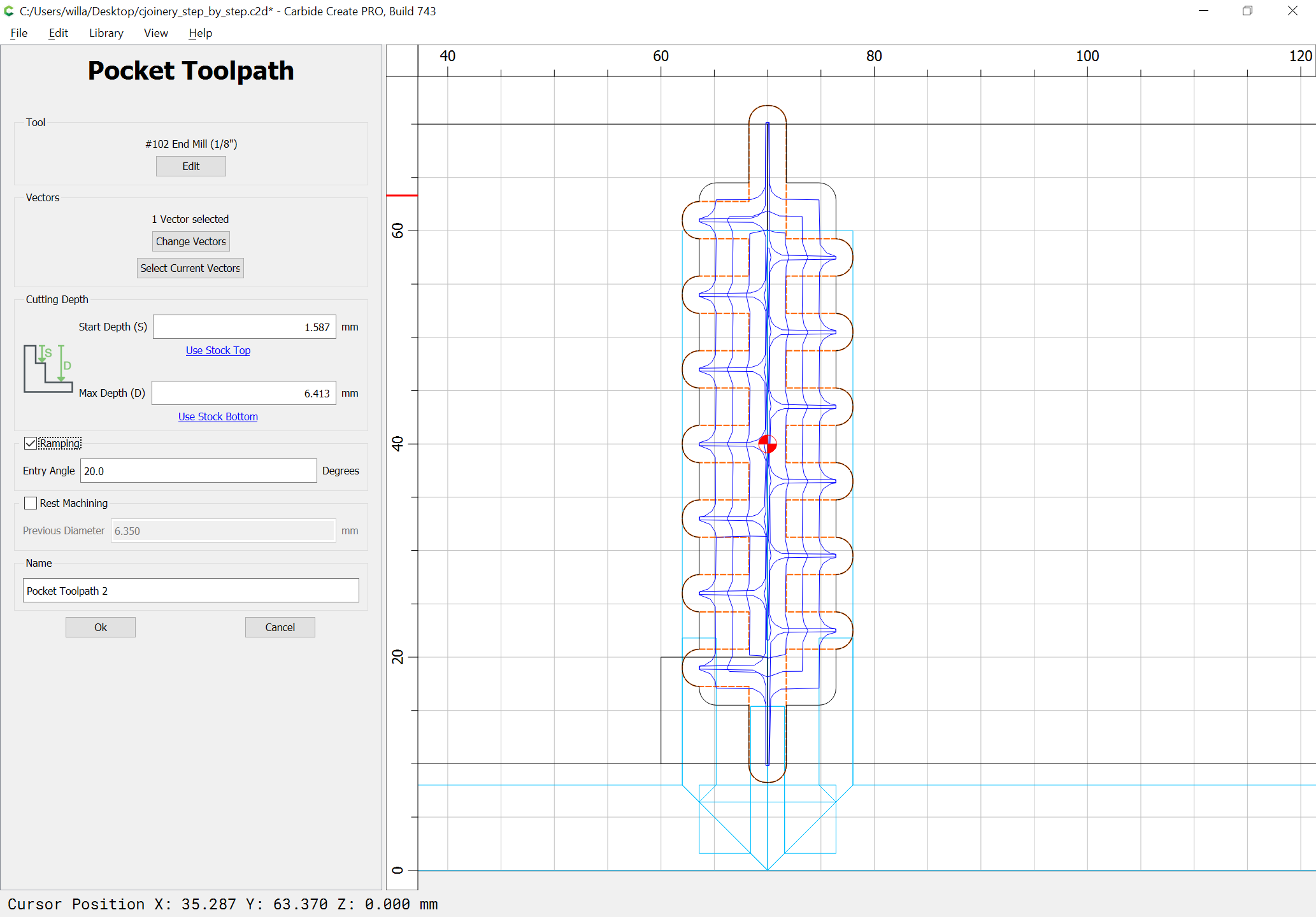
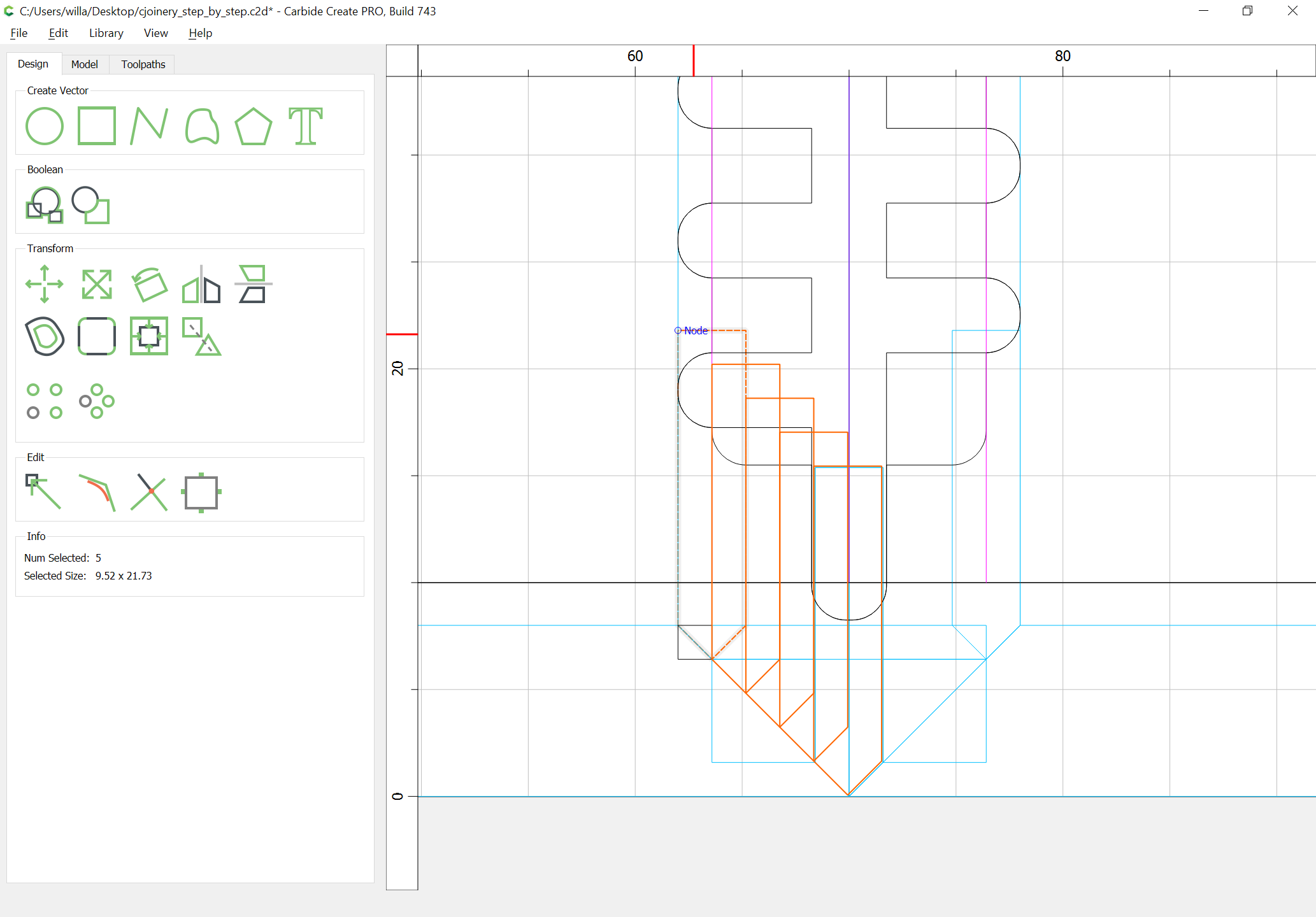
Next, determine what the minimum number of passes necessary would be:
One option would be to have a different number of passes on each side.
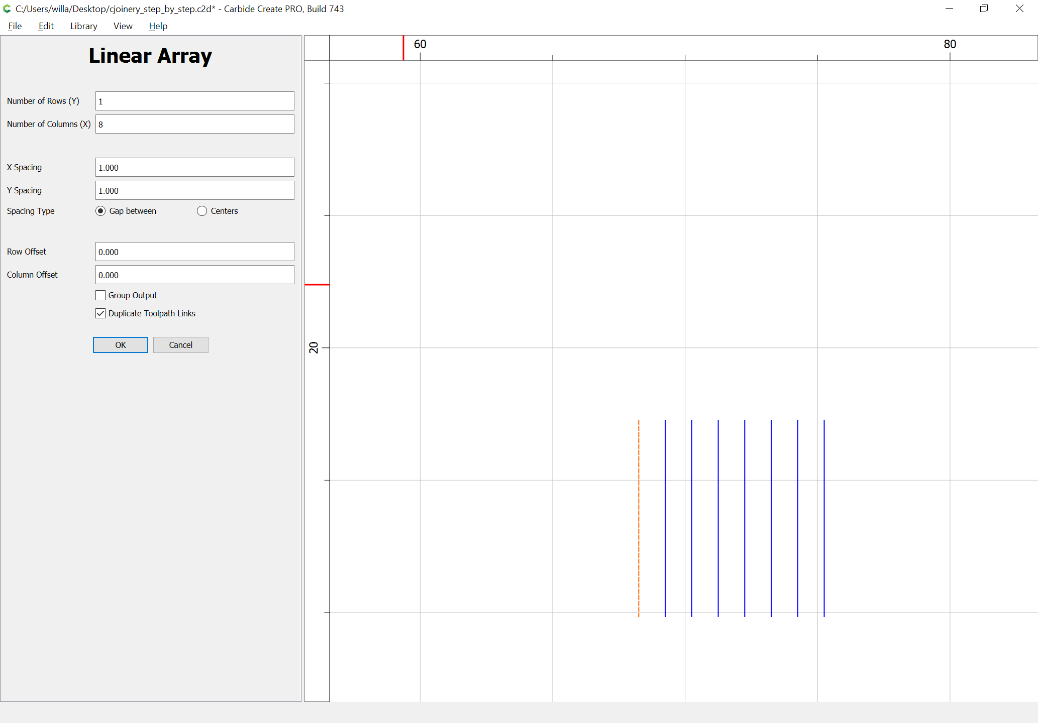
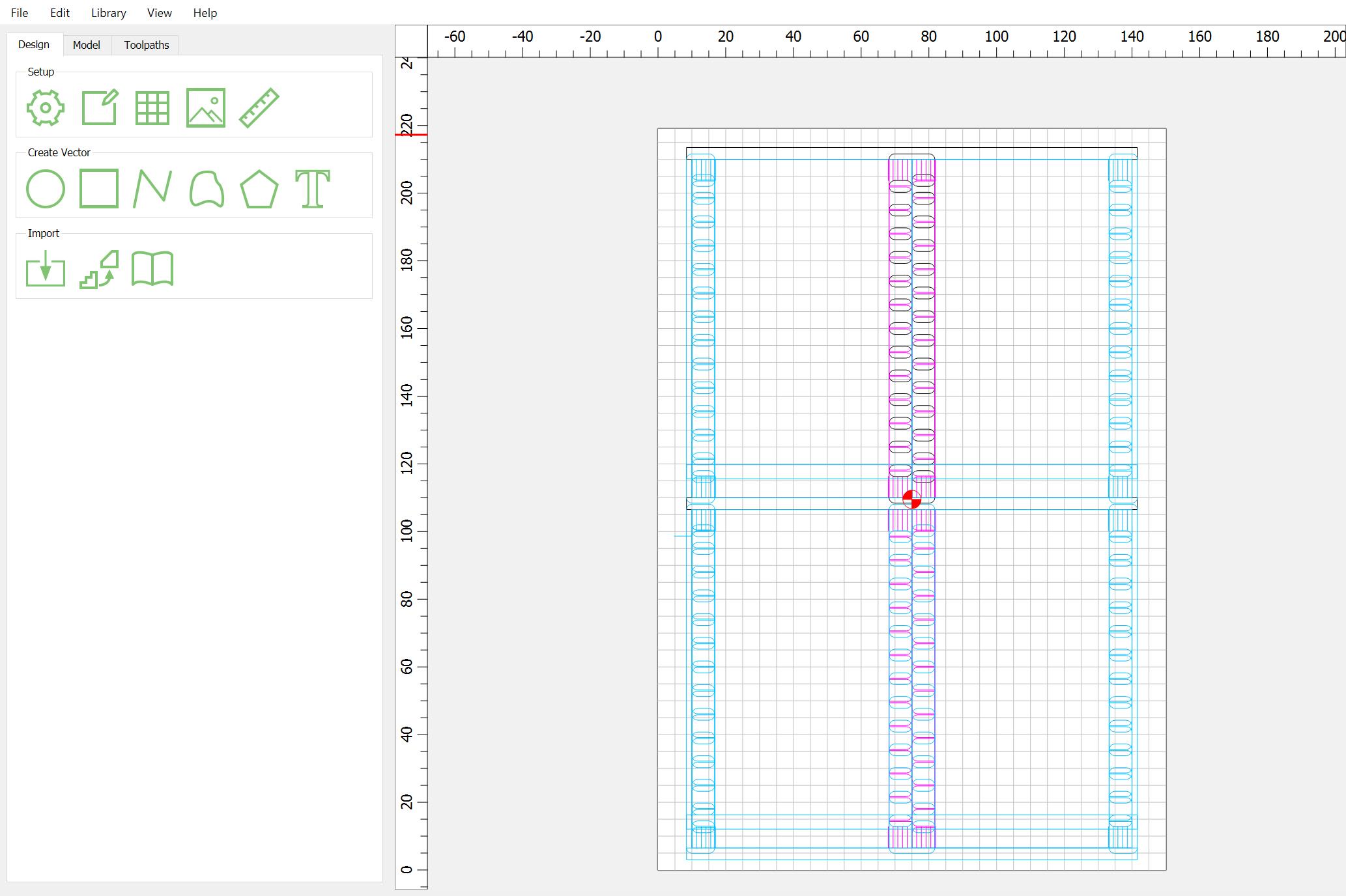
Draw in a suitable line for one cut and use Linear Array to duplicate it as many times as needed, w/ extras for origin and end points:
If need be, adjust the width of things to line up w/ stock thickness.
Then, measure the distance:
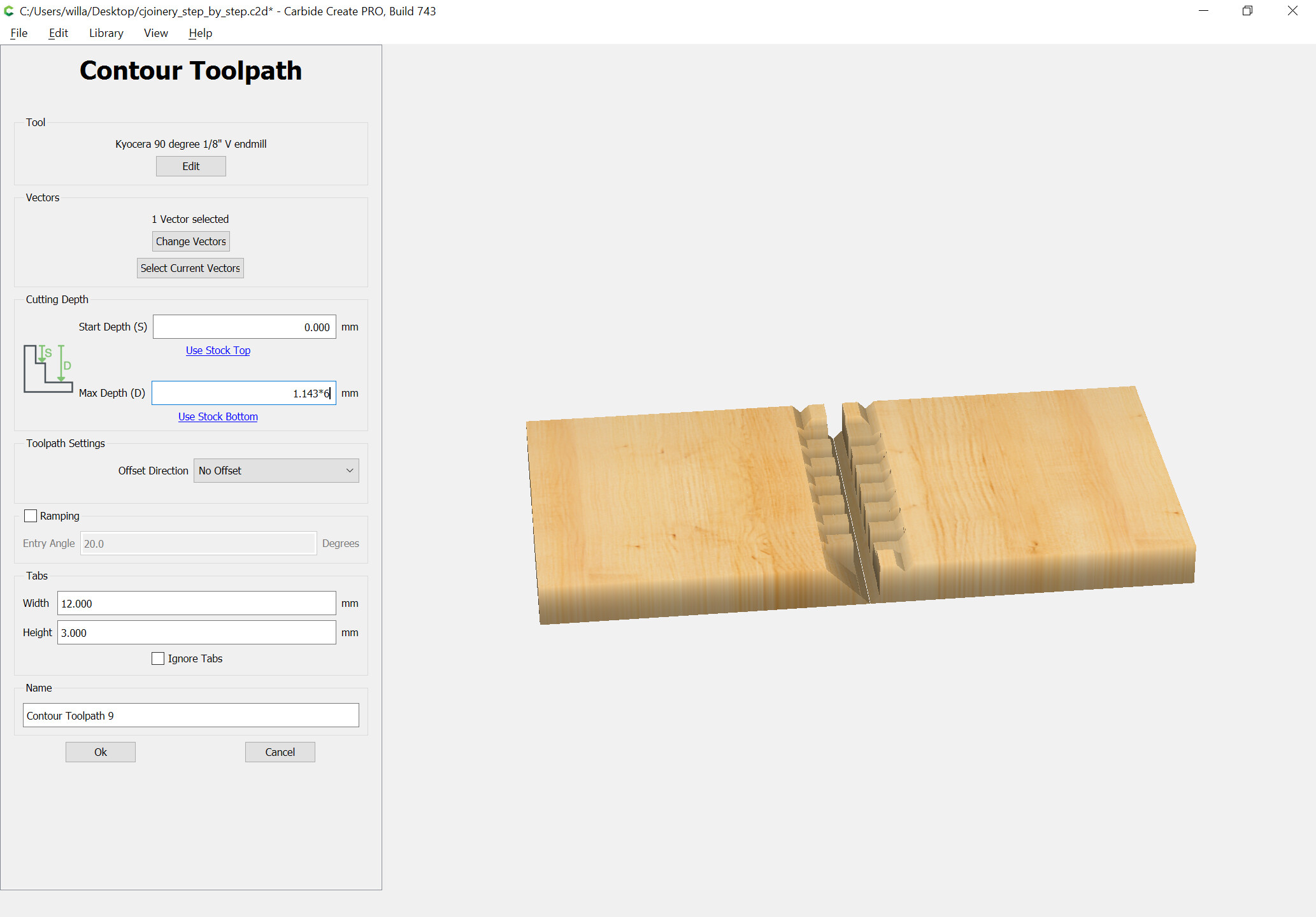
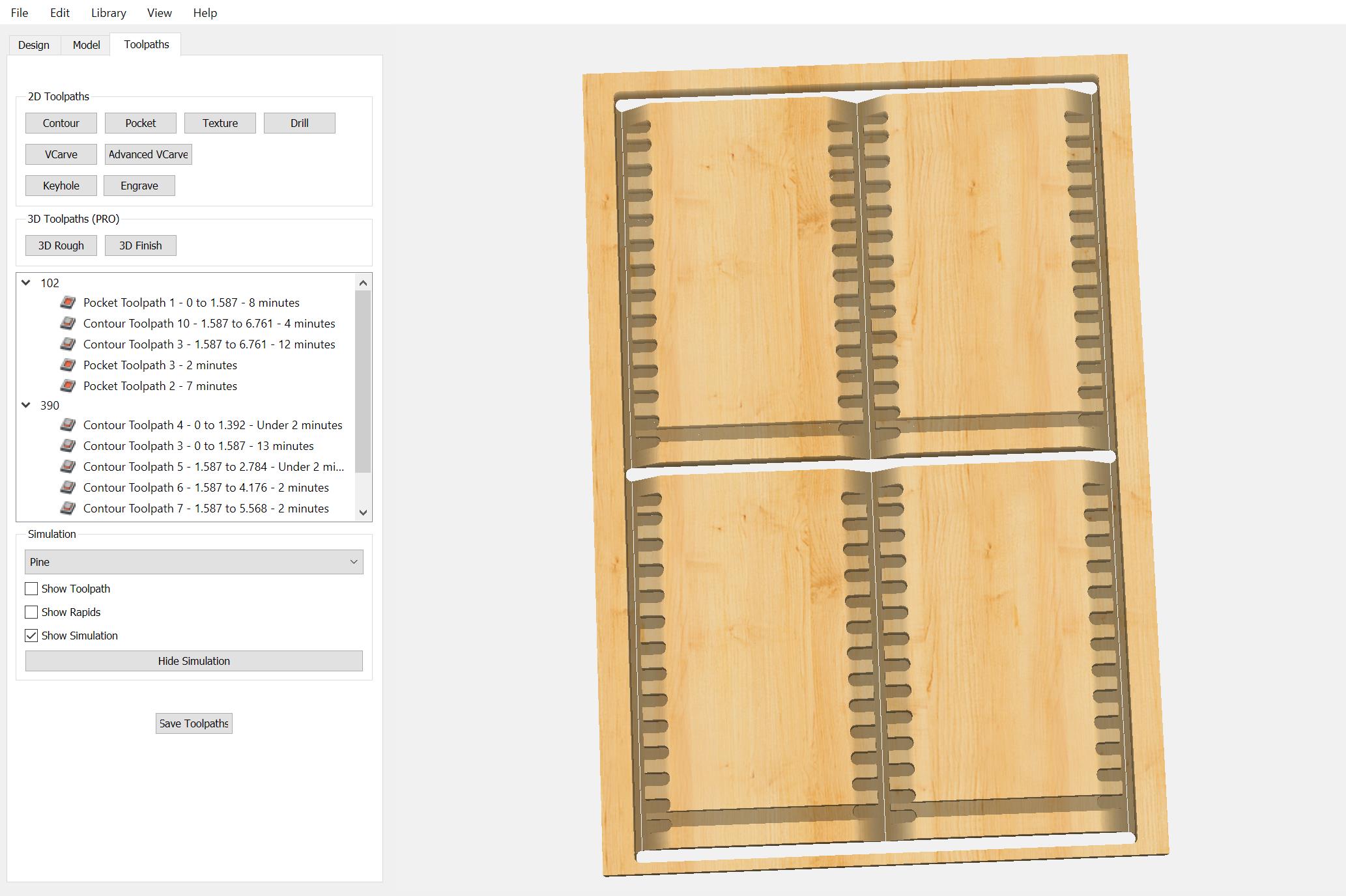
and assign toolpaths working down to the necessary depths:
This style of joinery is used in:
You have to use shorter geometry for carving only the V at the ends — if the 3D preview doesn’t show the fingers being left, adjust things until they show.
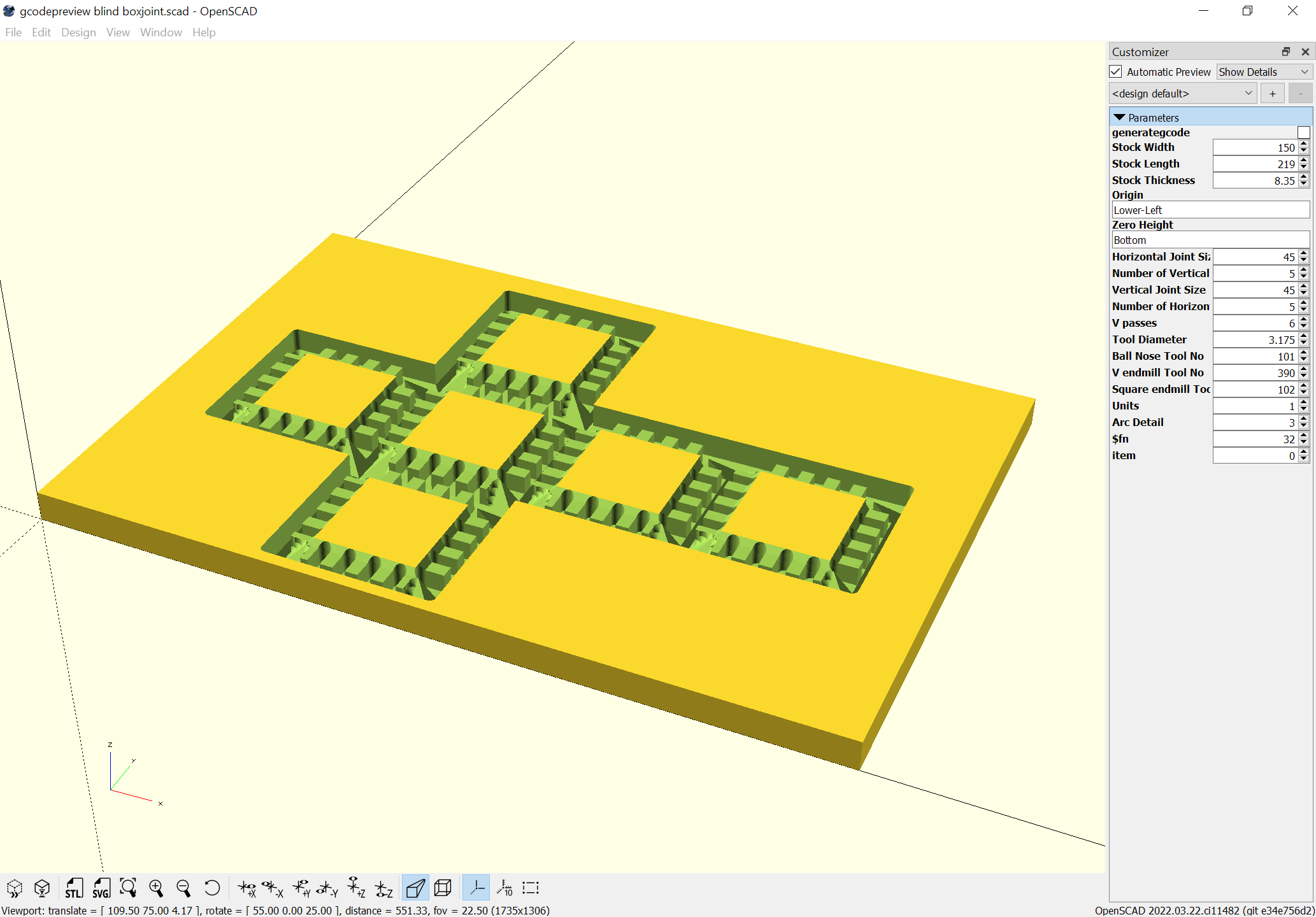
Worked up an OpenSCAD file for cutting these:
gcodepreview blind boxjoint.zip (852 Bytes)
Drawing it up in Carbide Create should be straight-forward.
Looking at it, one interesting observation is that it should be possible to have the corners cut as right angles, making for more efficient toolpaths.
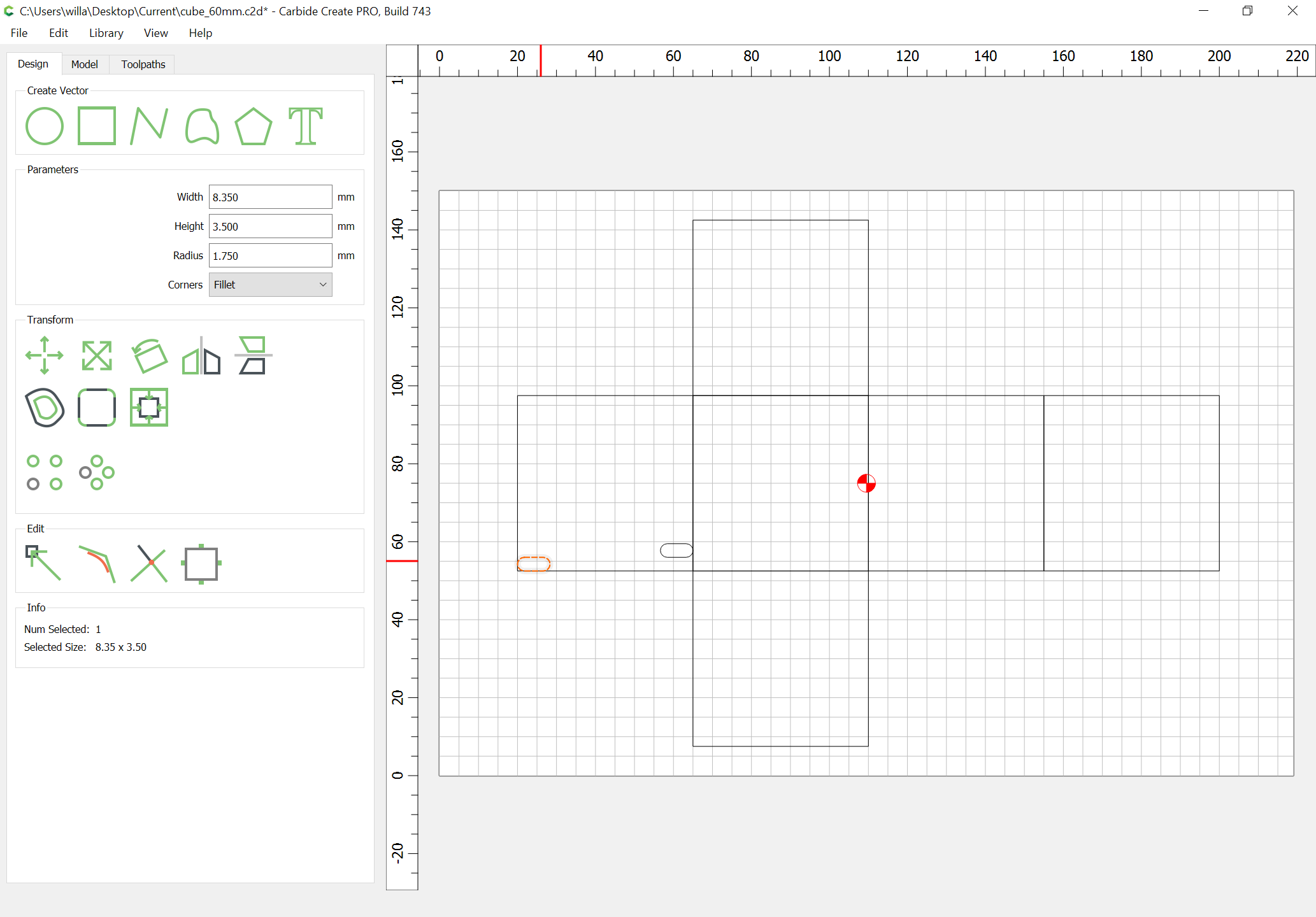
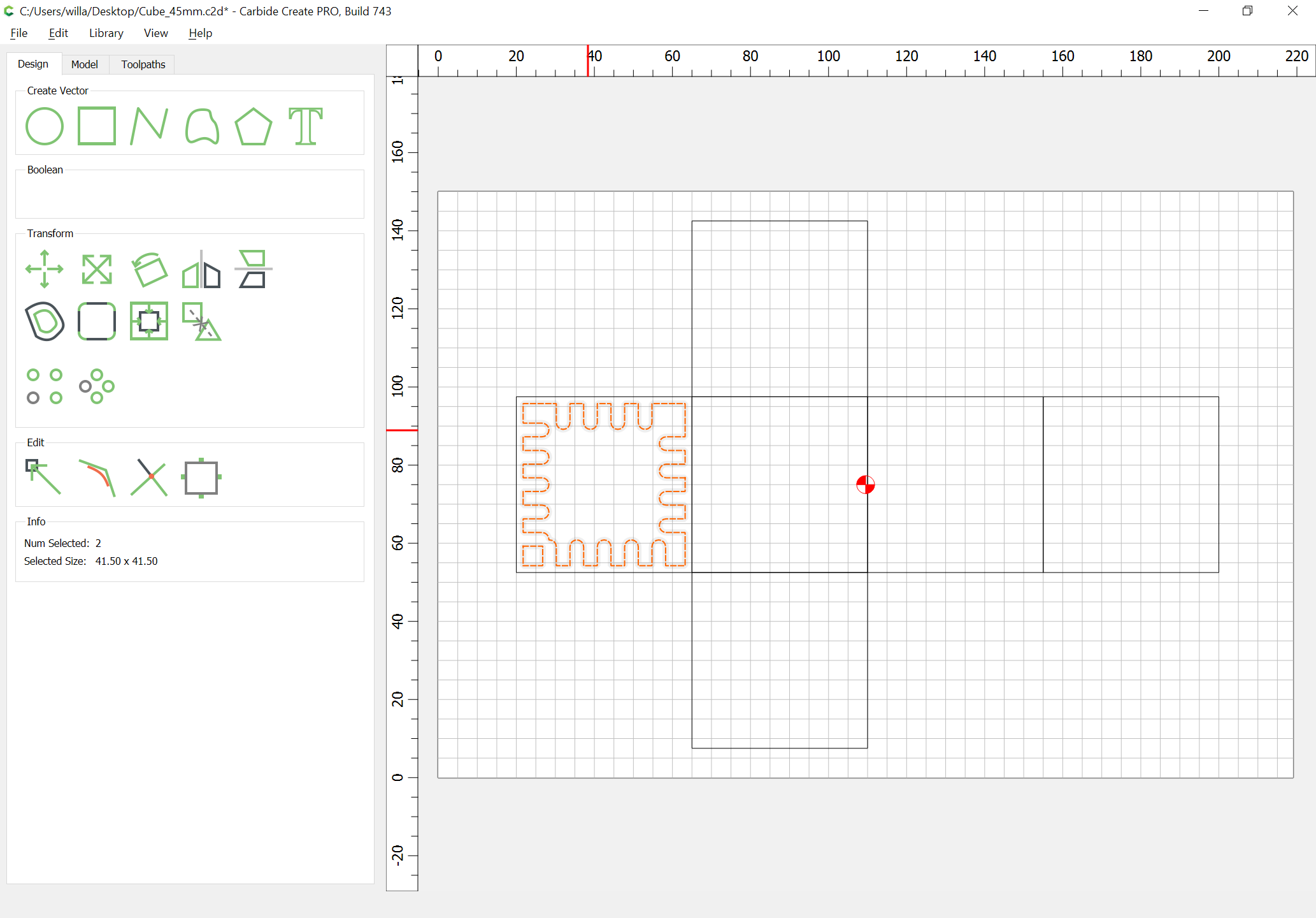
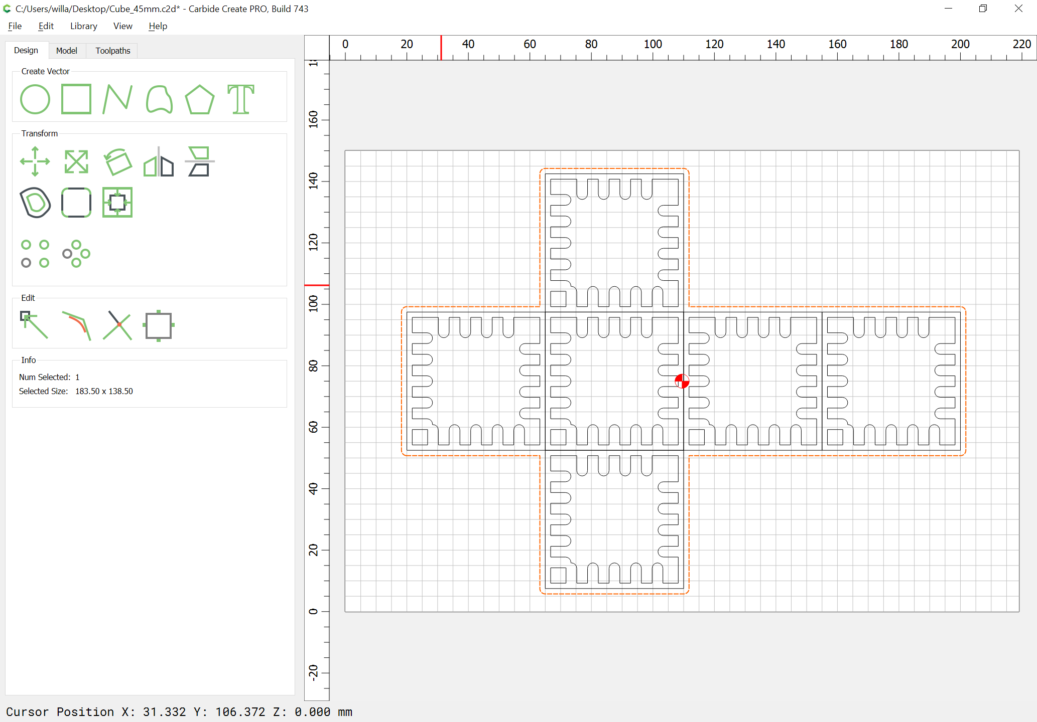
First, draw up all the squares:
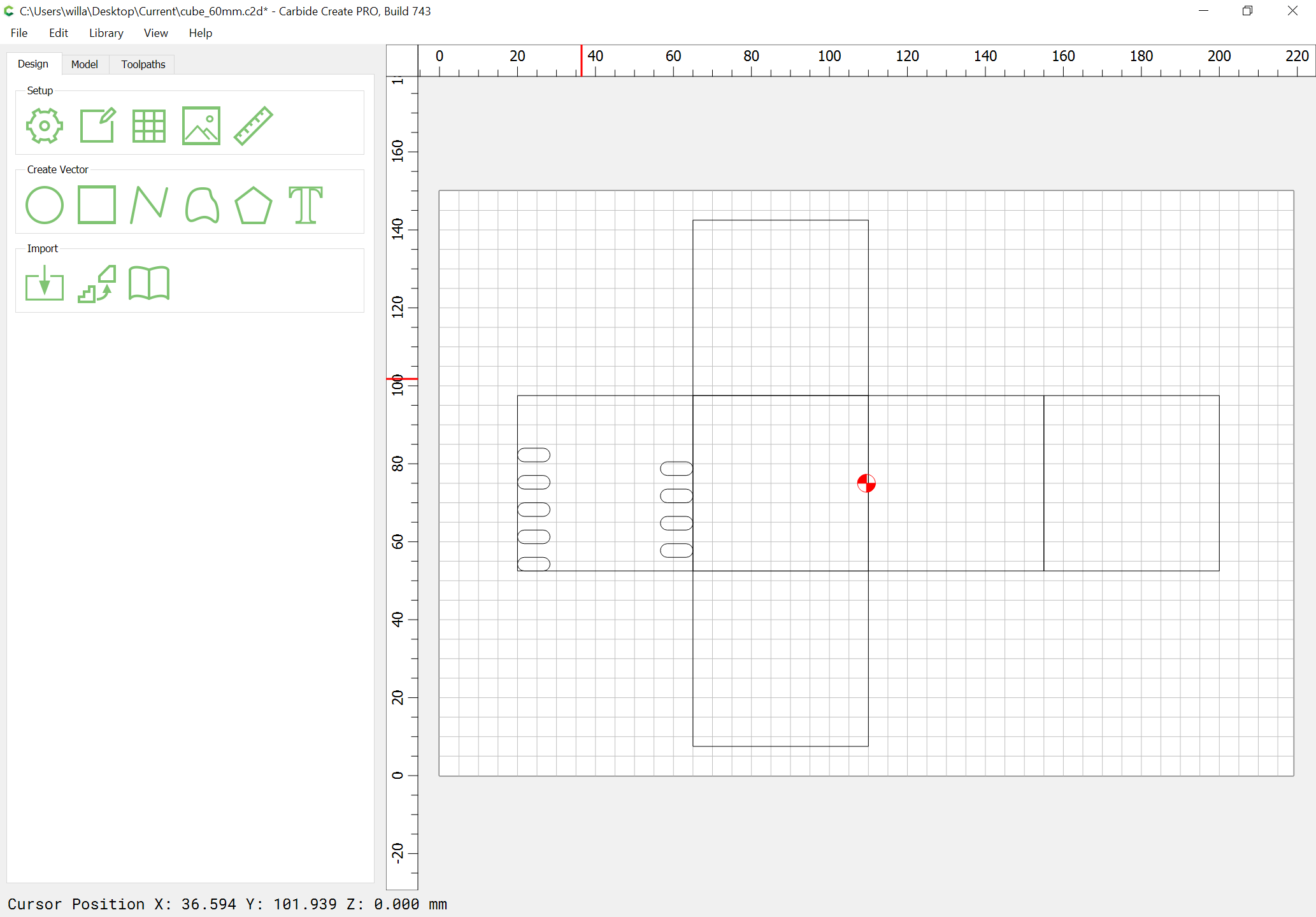
Then, draw in a paired set of fingers using Linear Arrays:
(size is stock thickness x endmill diameter plus 10% or so)
Delete the extra:
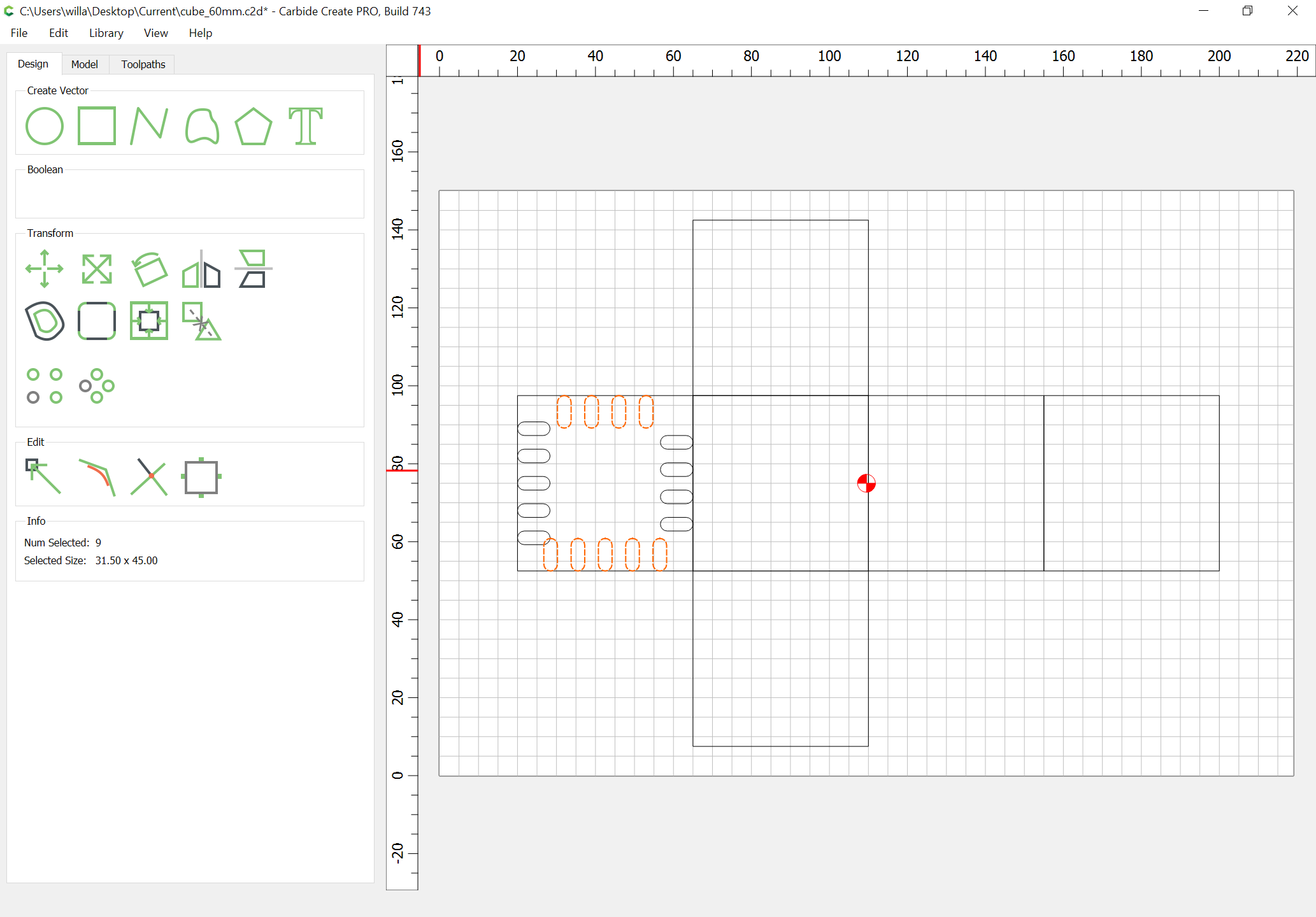
Select all and group:
Select a face and align to center:
Duplicate just the geometry for the fingers and rotate 90 degrees:
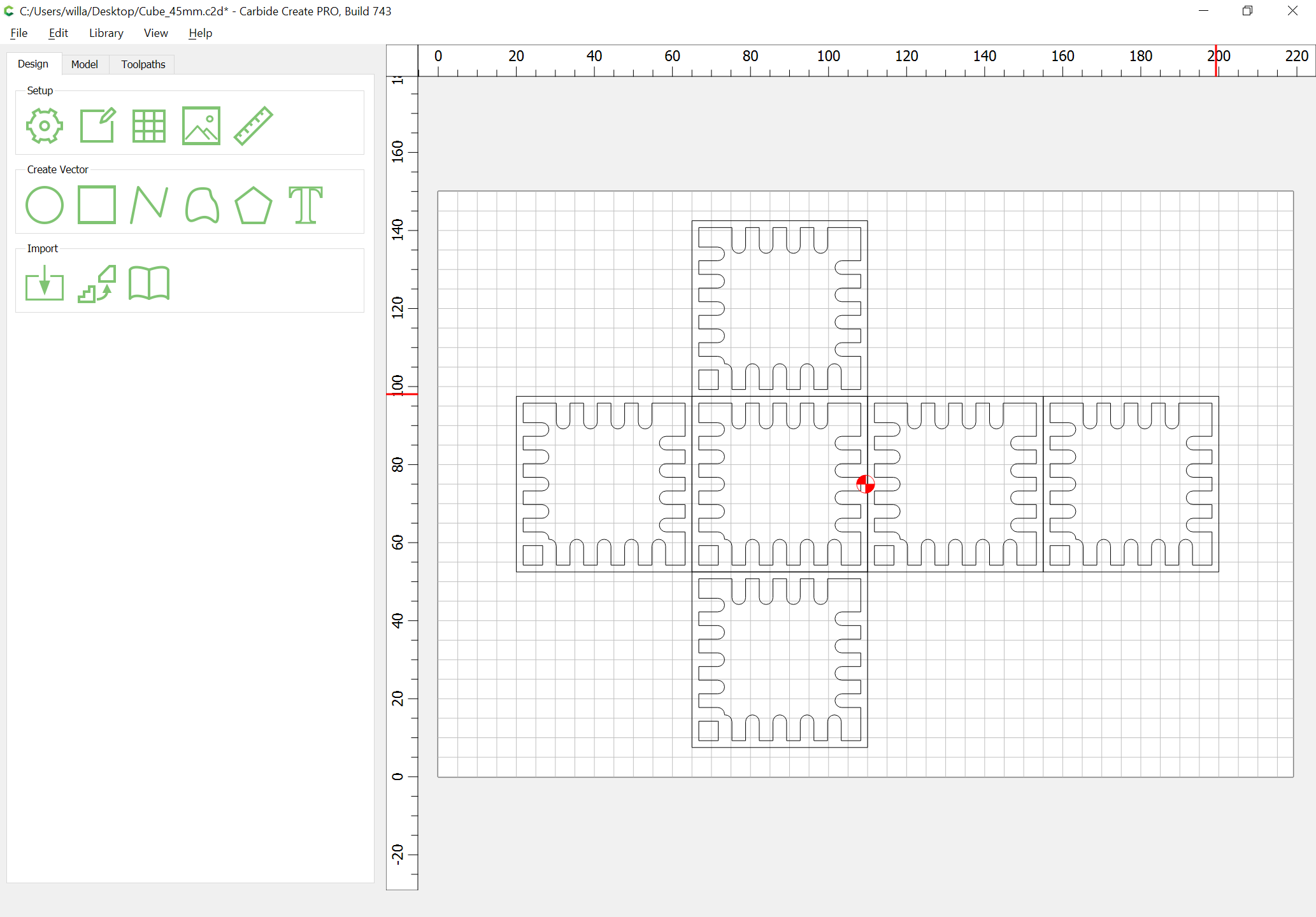
Draw in geometry to cut the central channels:
Duplicate and rotate as necessary to encompass all 4 sides:
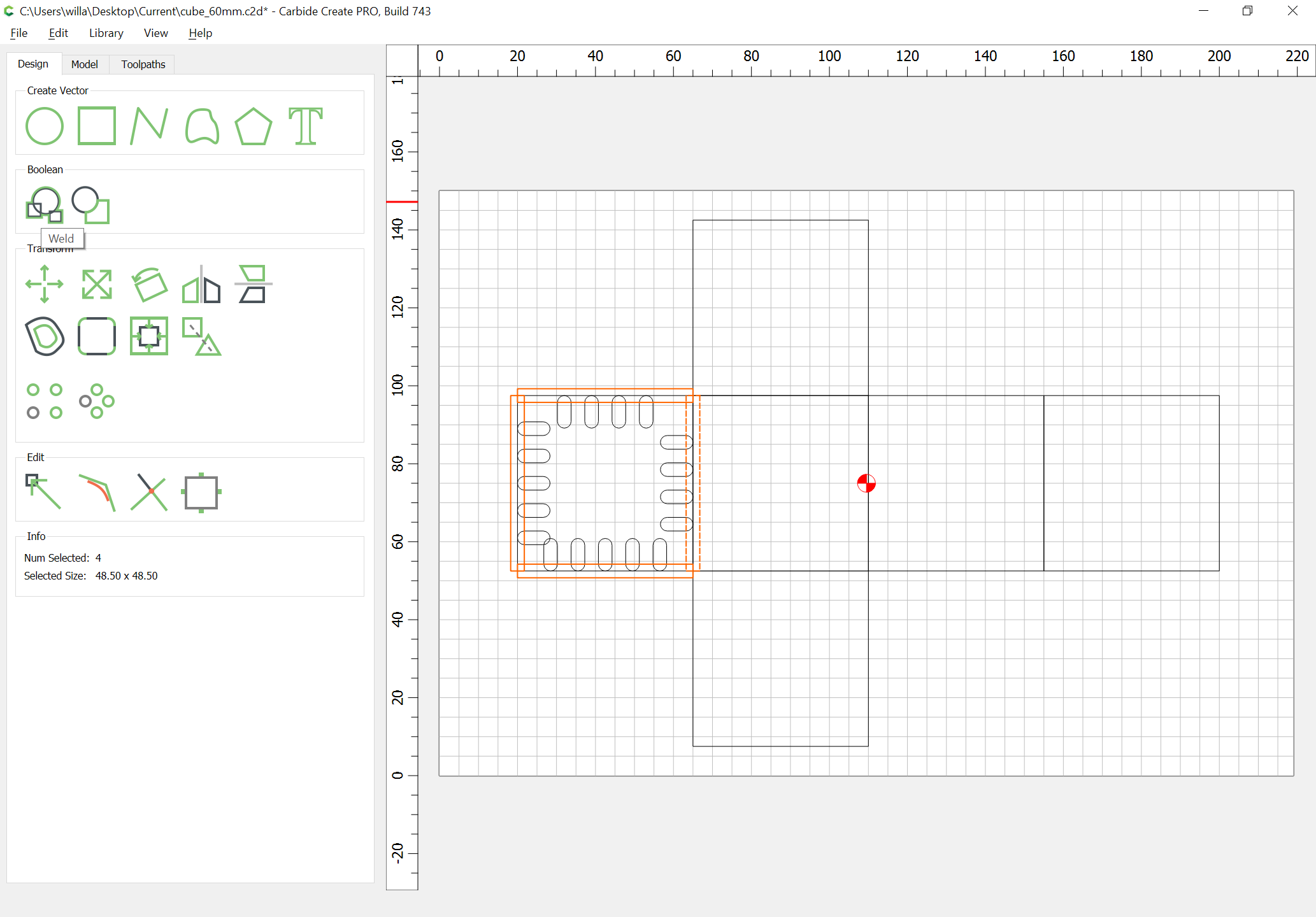
Select all four and Boolean Union:
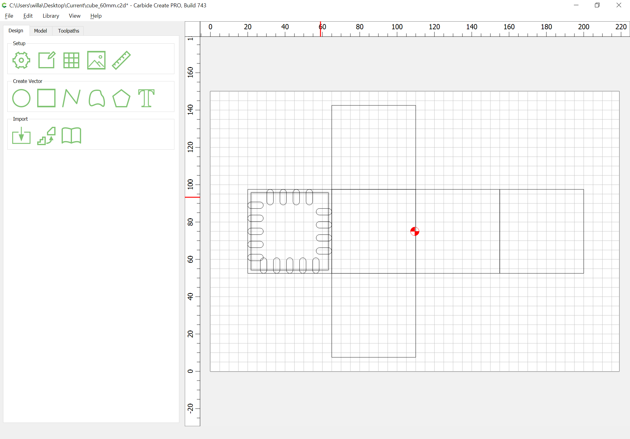
Delete the unnecessary outer geometry:
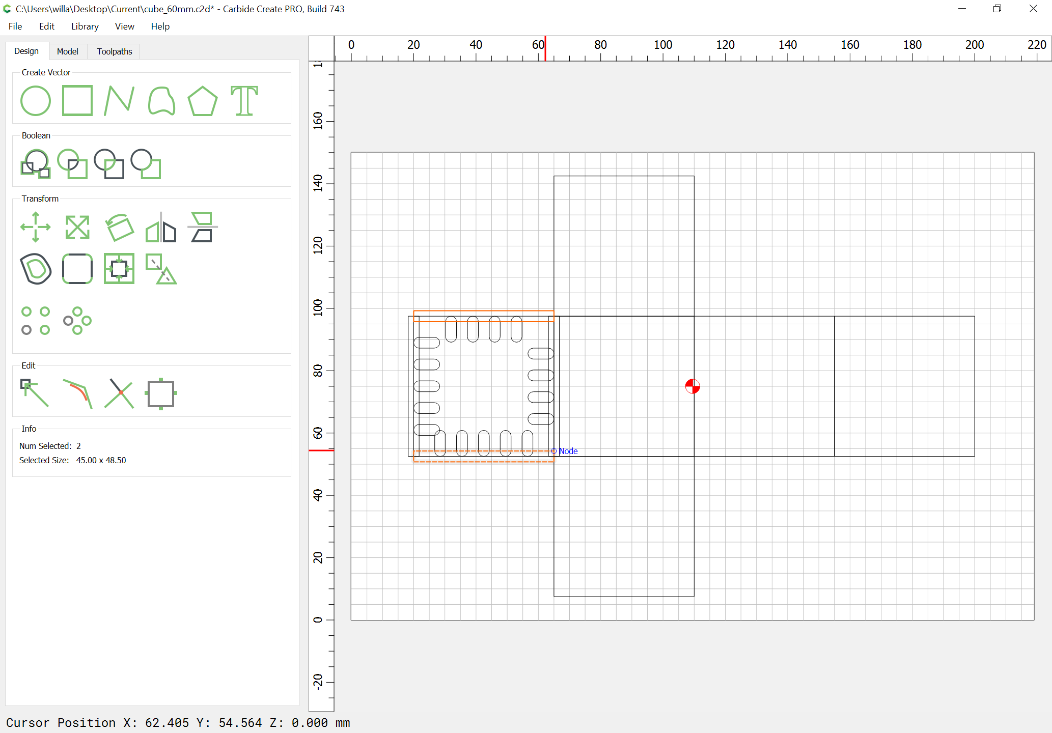
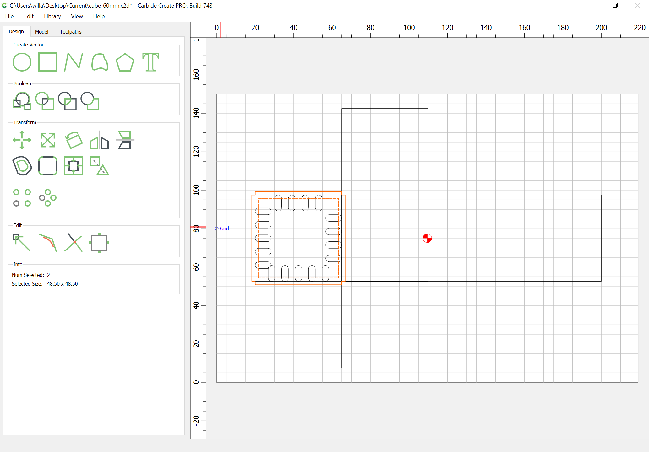
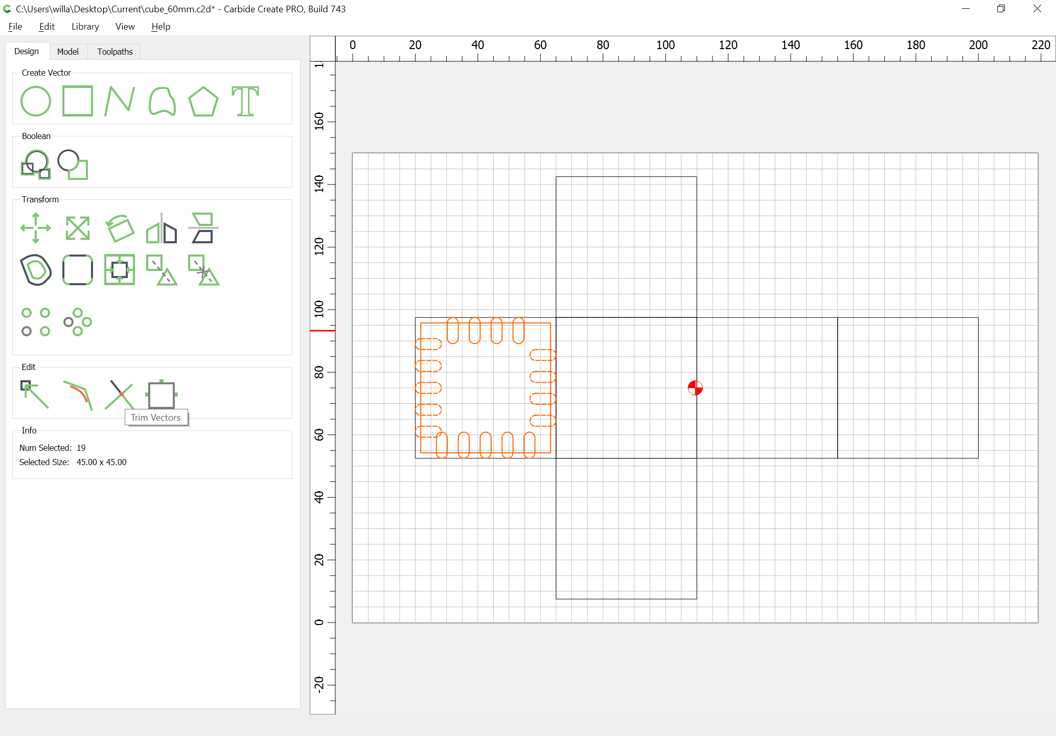
Select all the finger joint geometry:
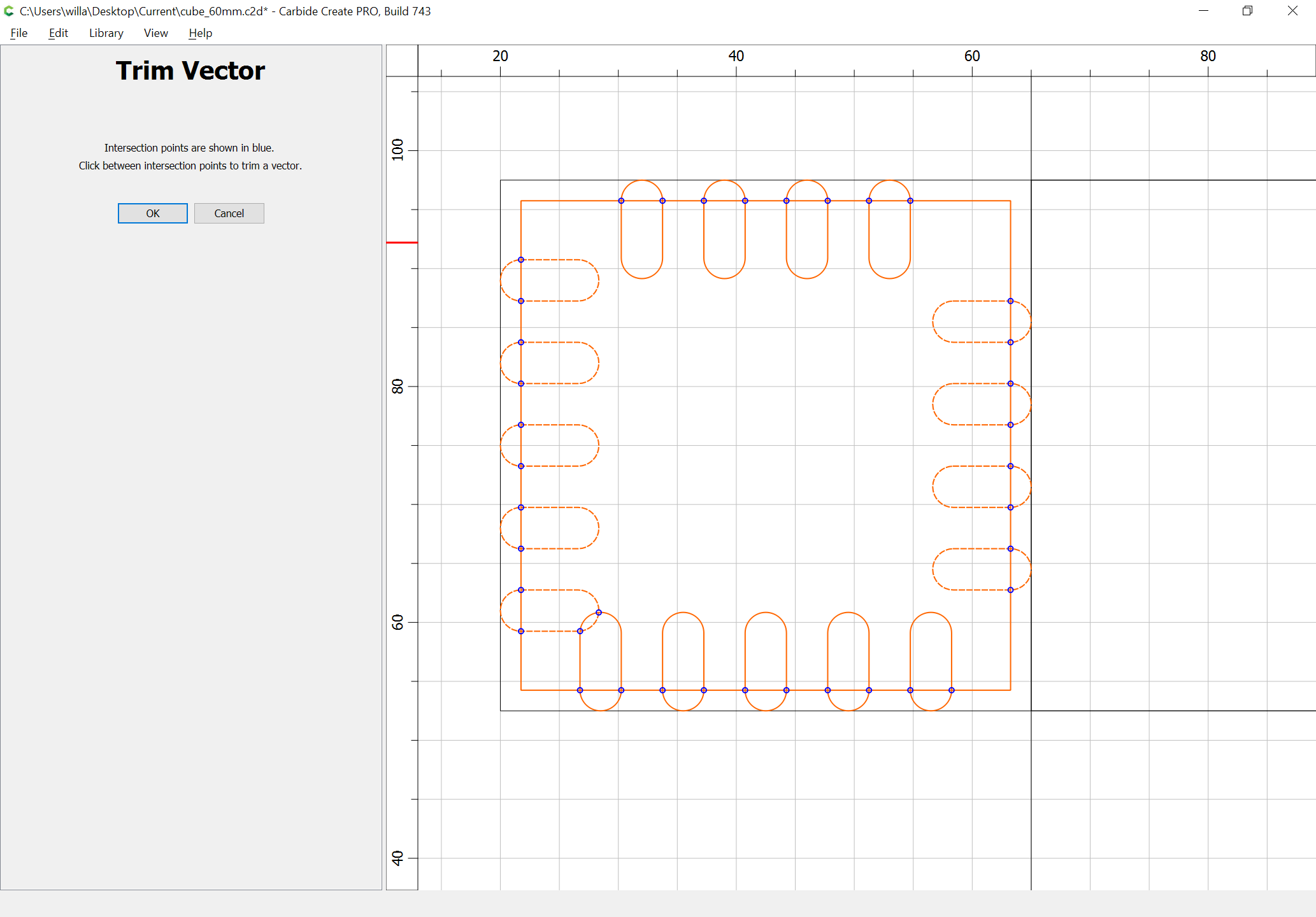
and use Trim Vectors to eliminate the unnecessary geometry:
Then use Join Vectors to close:
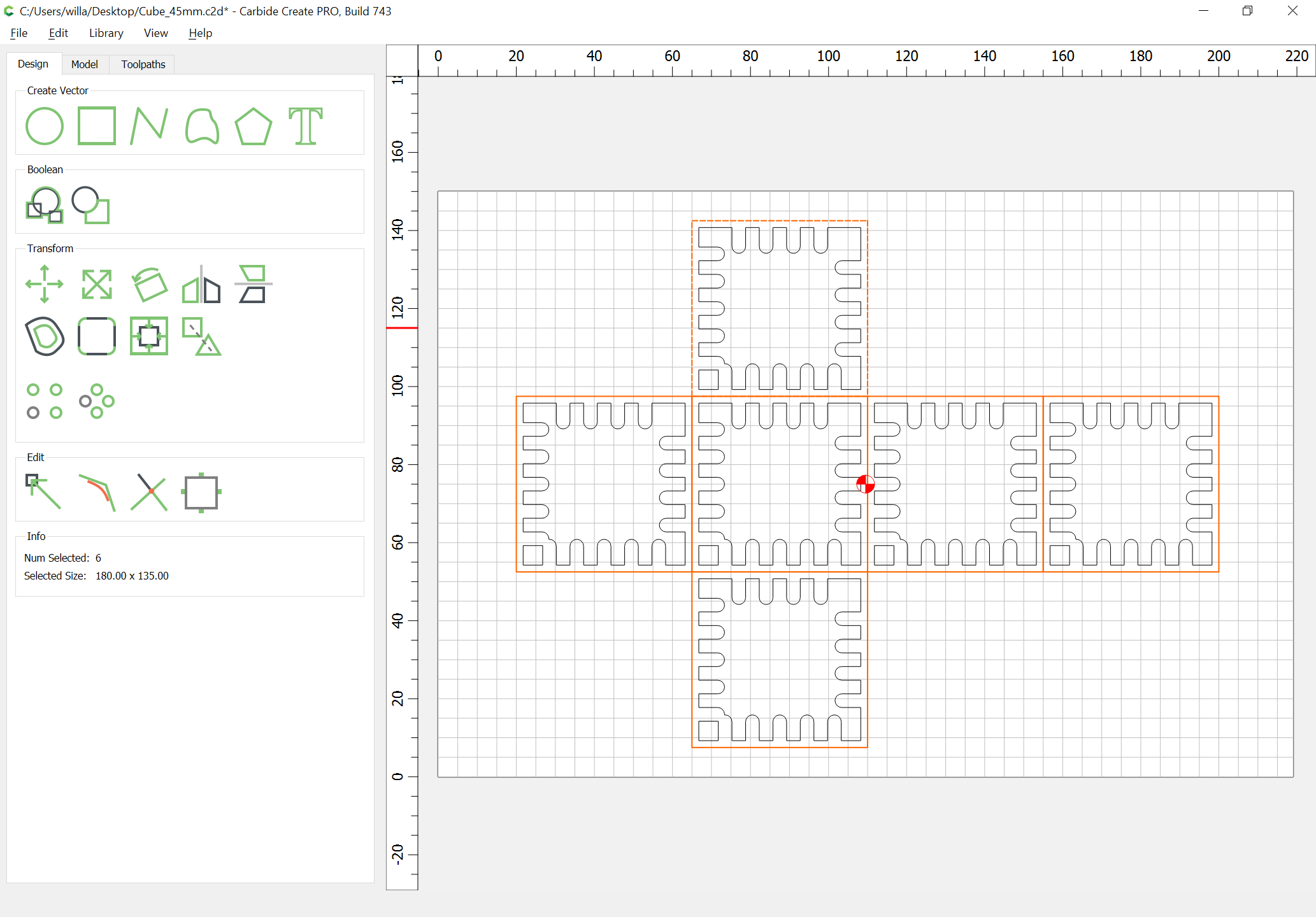
Duplicate into the center of each other face:
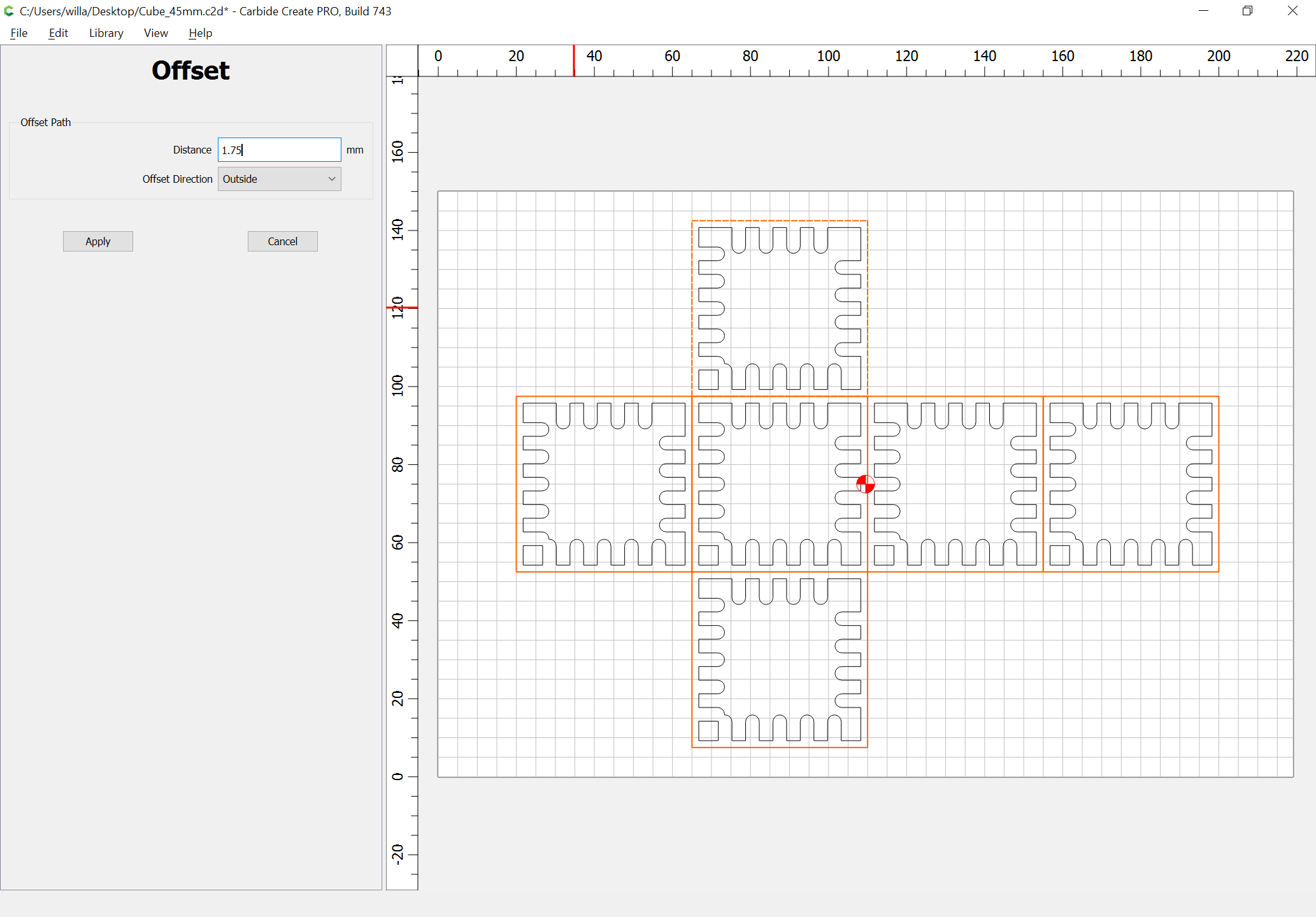
Select all of the faces:
and offset to the outside by half of endmill diameter plus 10%:
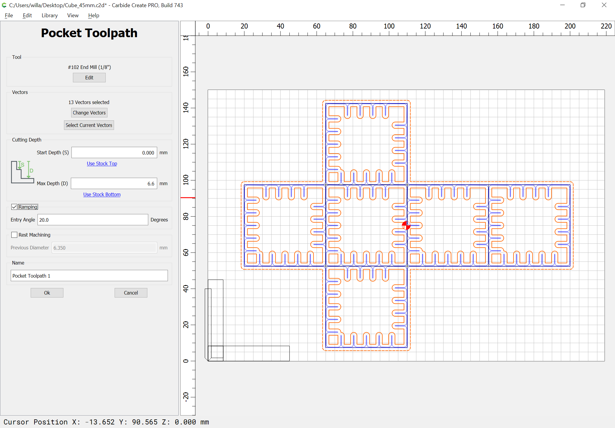
Next assign a toolpath which cuts to the bottom of the pockets, but this requires drawing up the joint in profile.
Drawn up in profile we get:
So select all of the fingerjoint geometry and assign a Pocket toolpath to a depth of 6.6mm:
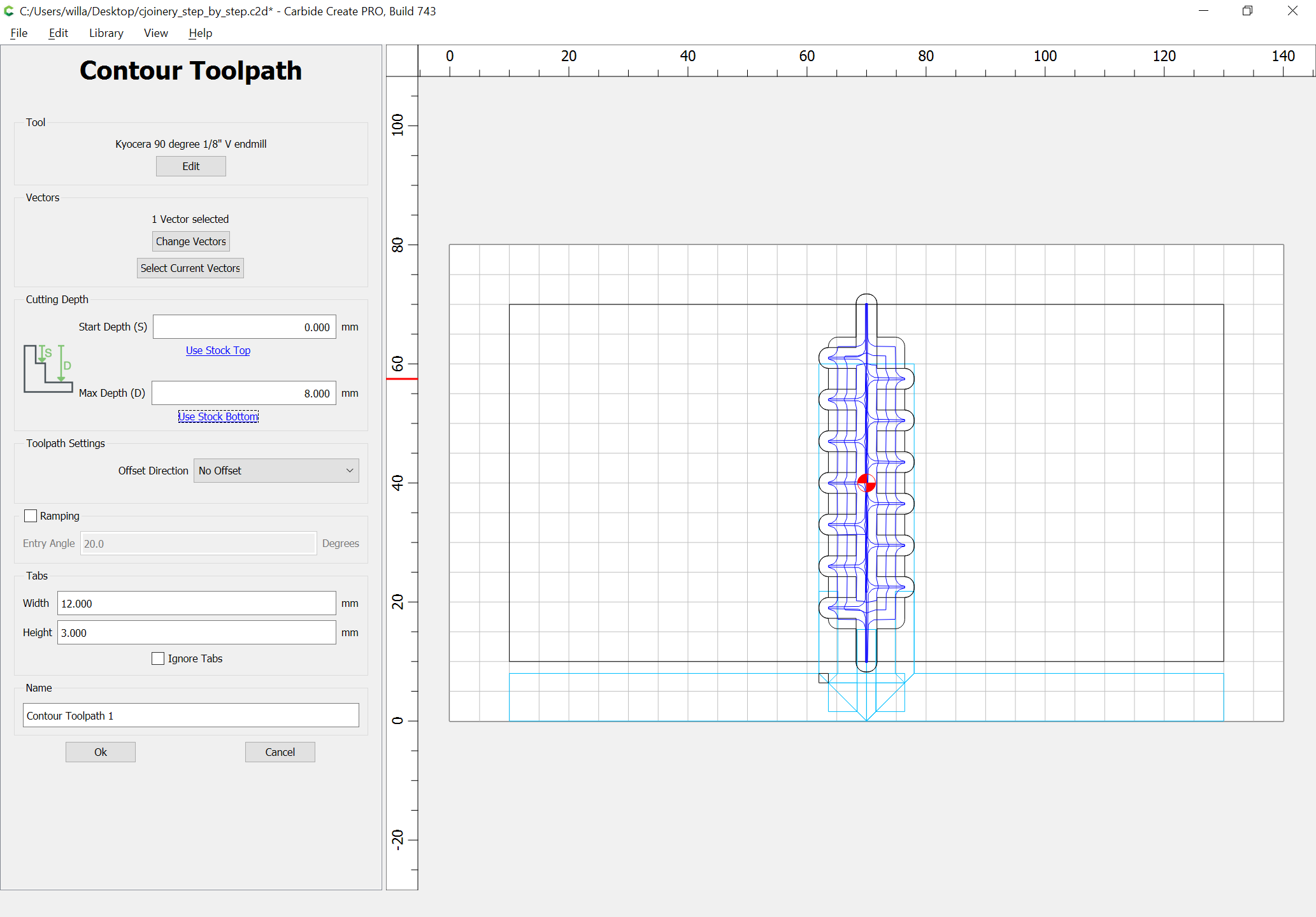
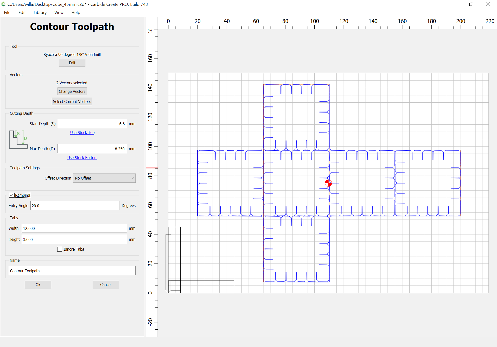
Next, draw in the geometry for the V endmills — the bottoms are of course quite obvious, but it’s not quite possible to draw them in as a single polyline:
and this gives a good idea of how the joinery will work:
leaving just pockets to clear the tops of the fingers so that they will not require dogbones (which would require a third tool) and a series of V cuts to cut the miters at the corners.