Lastly we draw in the V endmills cutting the corners in the profile view:
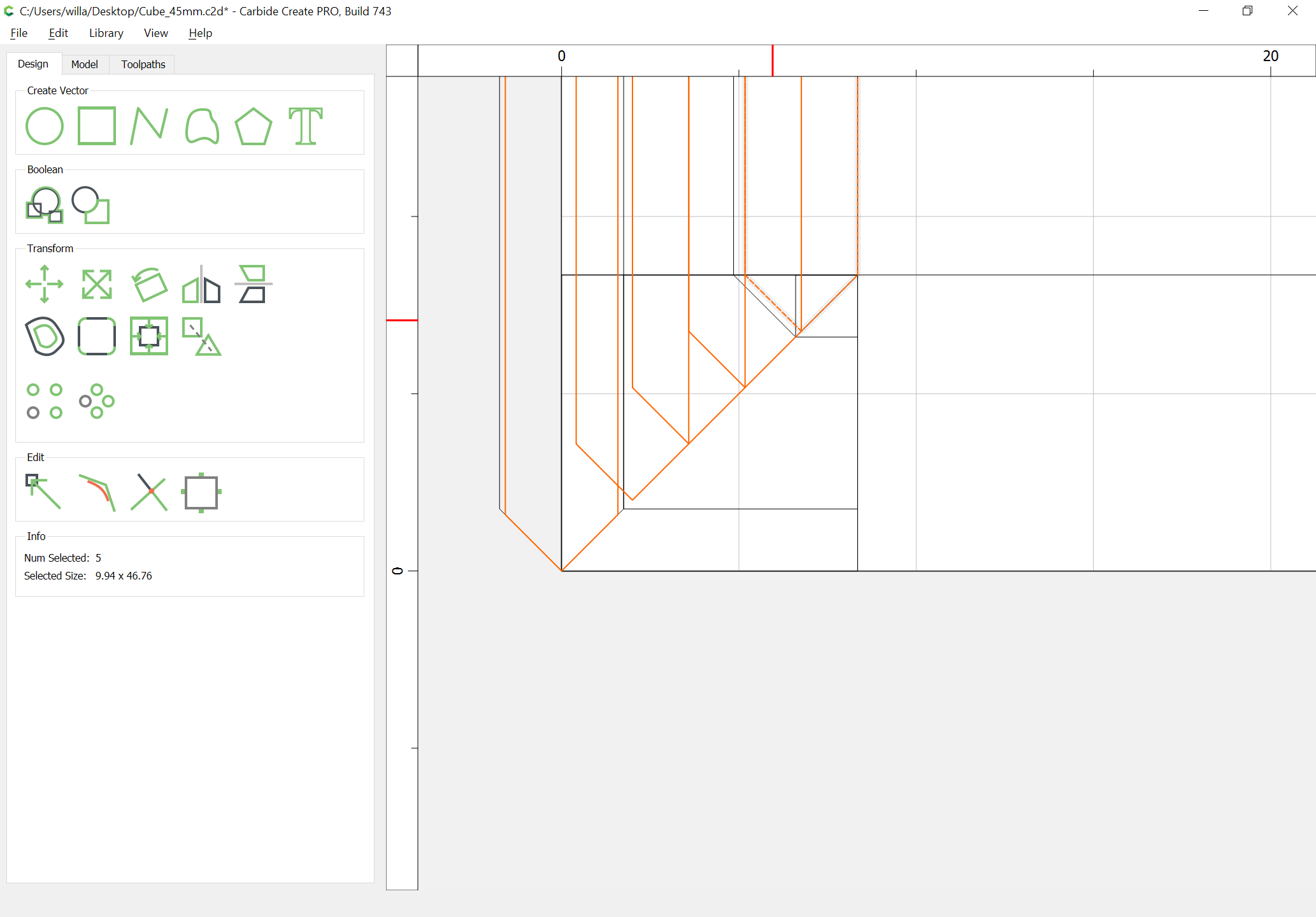
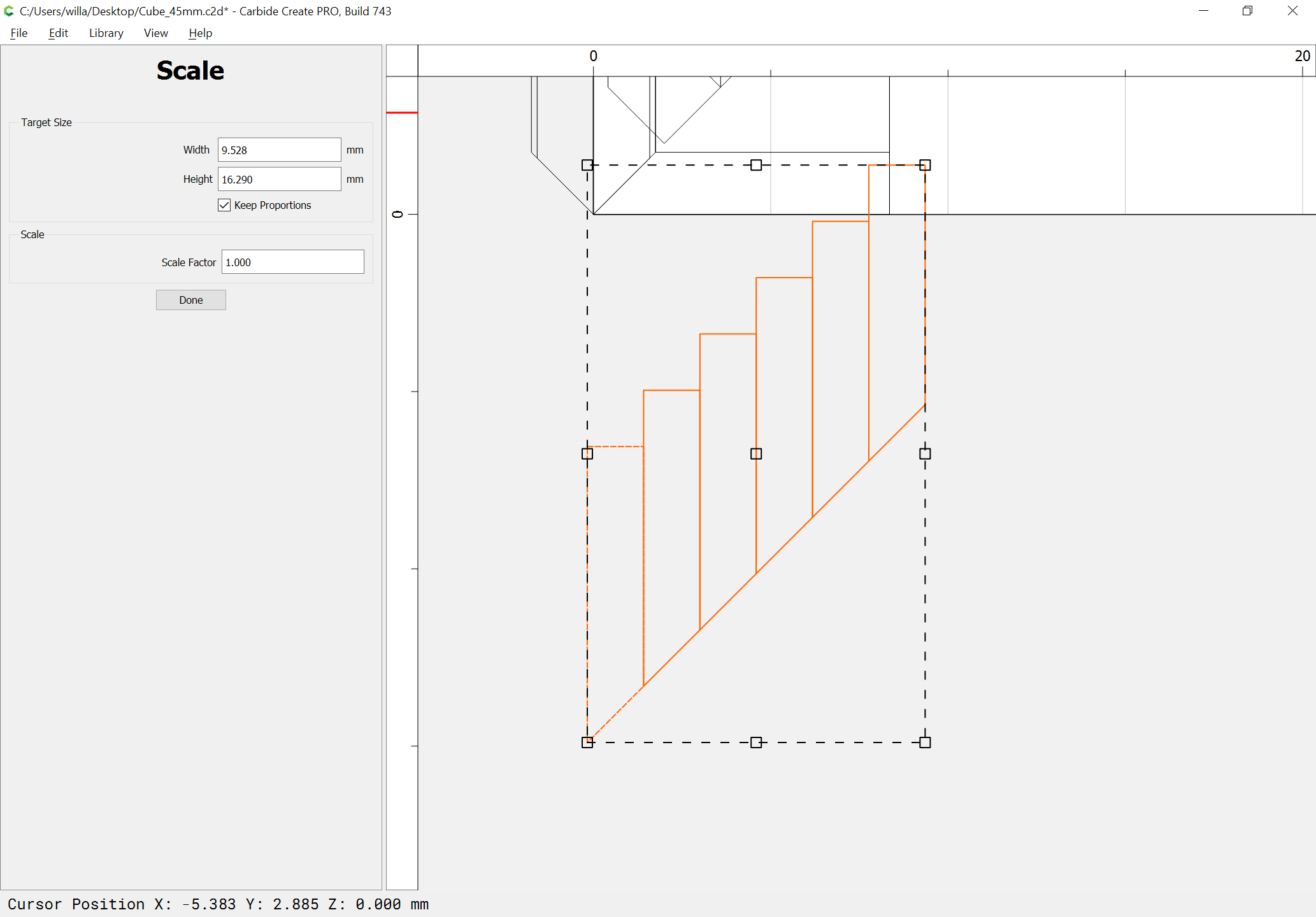
6 passes will be necessary — one easy way to draw this is to stack up 6 copies of one-half of the endmill:
and scale the width of it to the stock thickness:
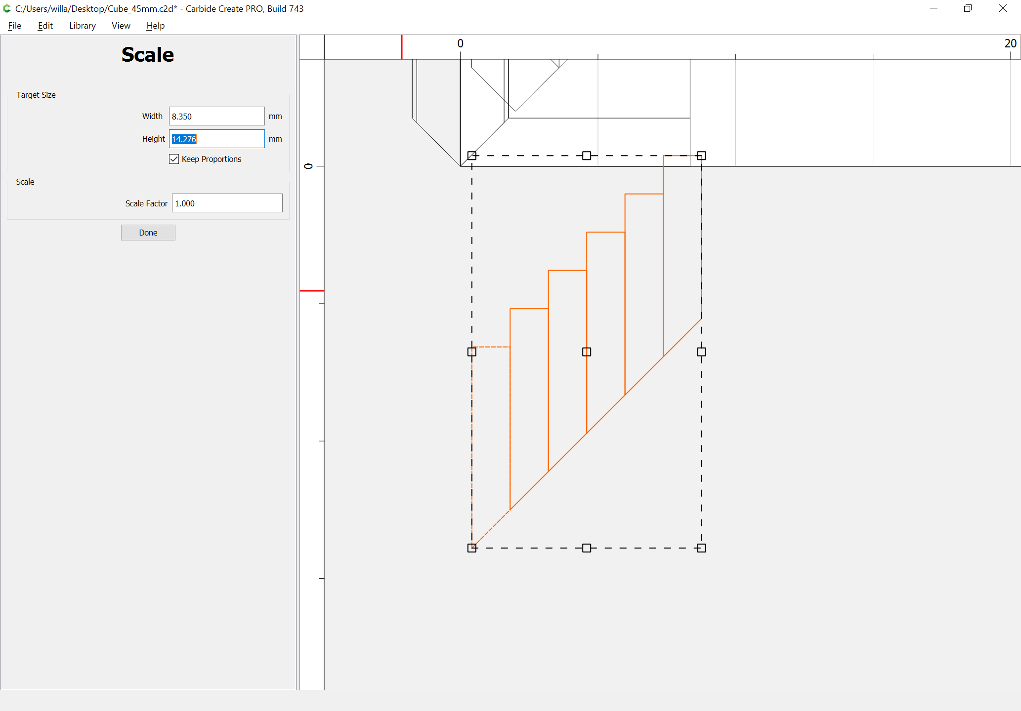
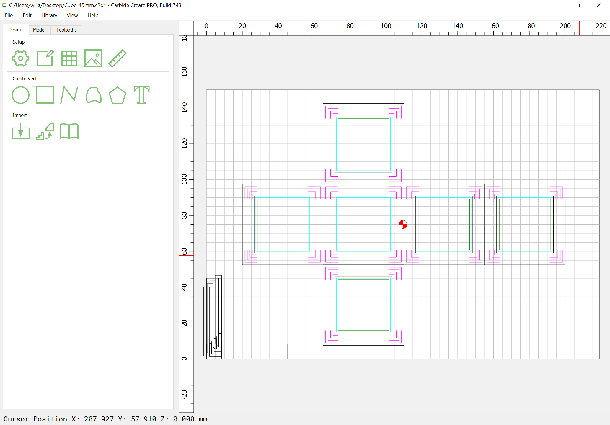
The bottoms of each may then be measured to determine the offset from the edge/top of stock, but the first thing which should happen is drawing in rectangles which are inset by stock thickness from the face rectangles and assigning a no-offset Contour toolpath to them at the top of the stock (well, 0.001mm below the top of stock — it’s not possible to assign a depth of zero to a toolpath):
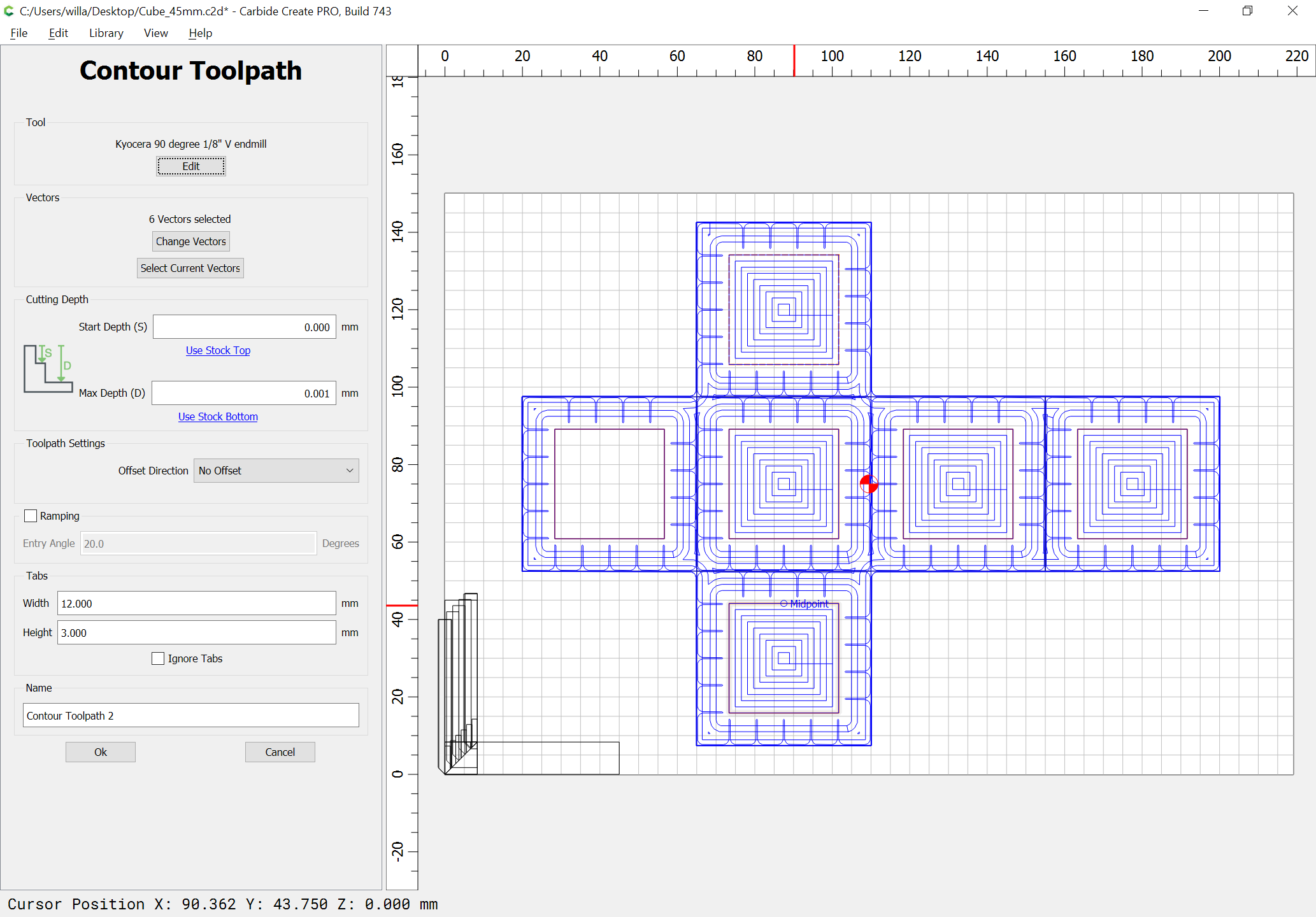
This covers the case of the stock being thicker than expected.
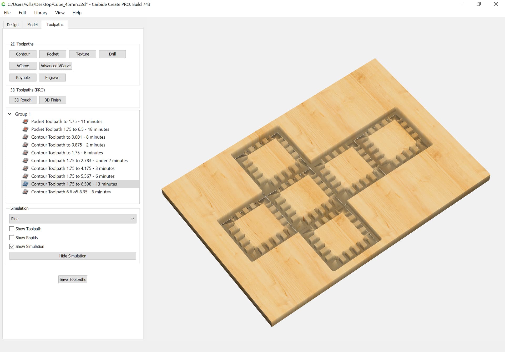
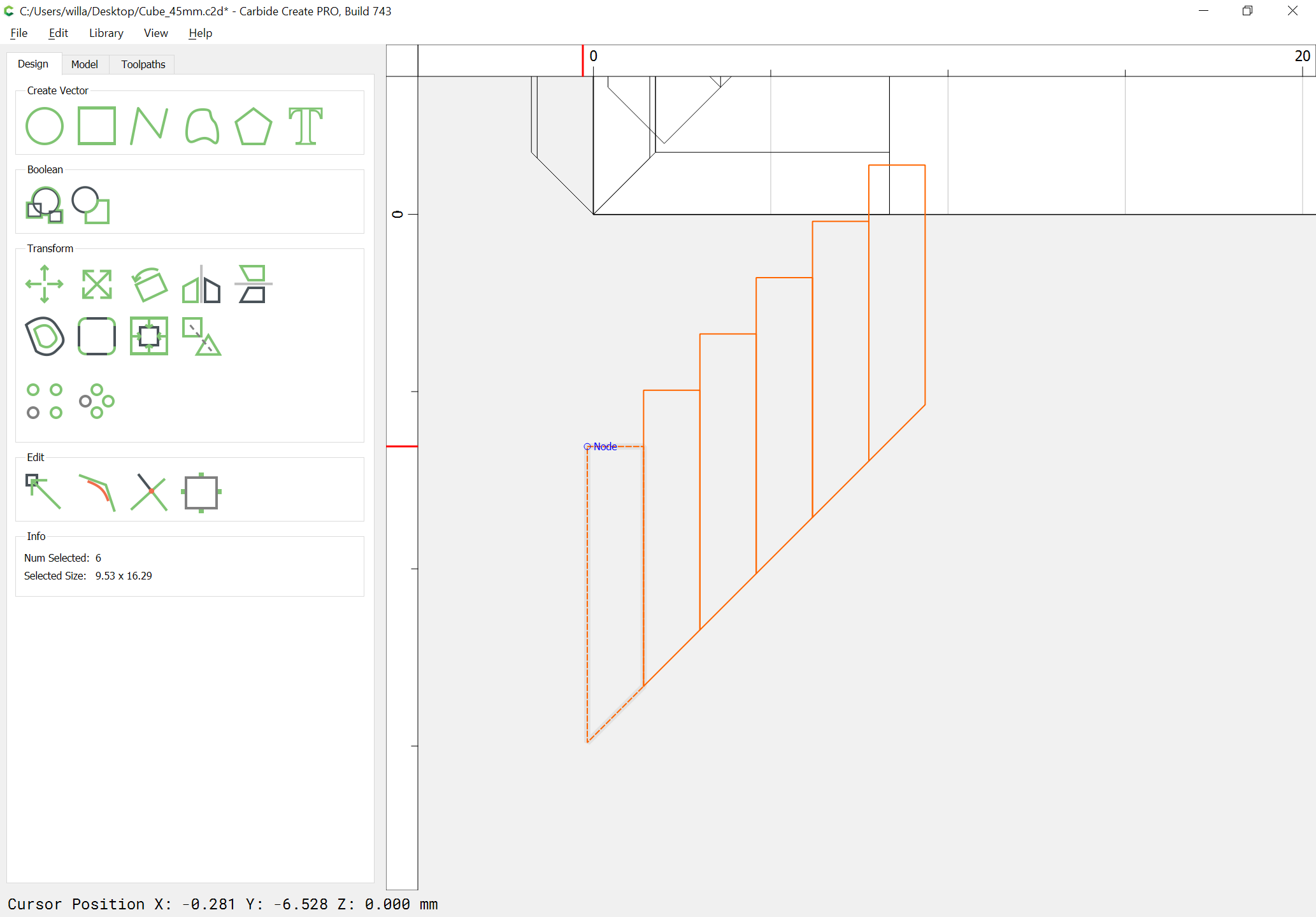
The next two V contour toolpaths continue this, working down by first one quarter the distance, then to half the depth of the endmill diameter plus 10%:
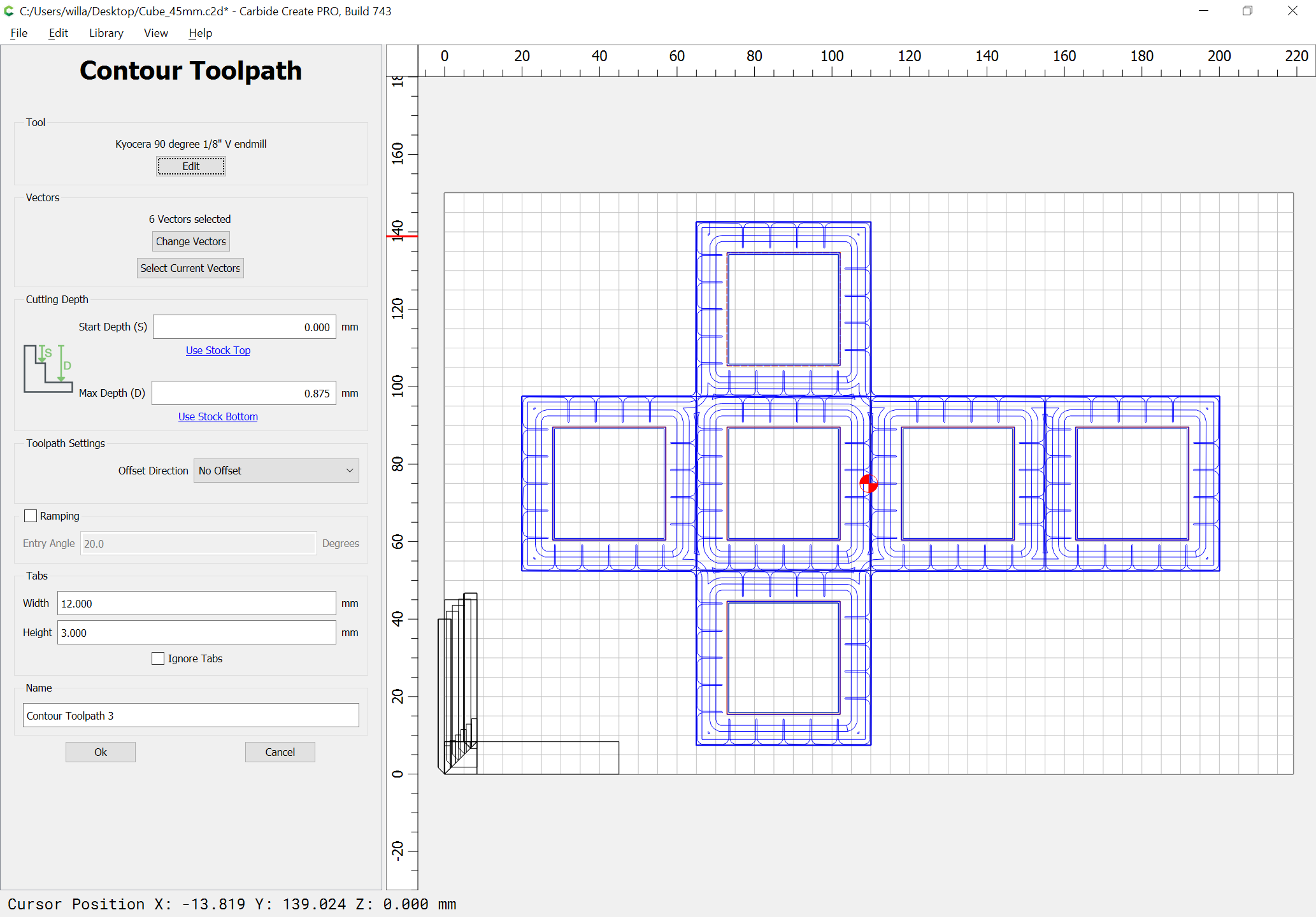
For each successive layer, draw a rectangle of a size to match the desired depth/offset:
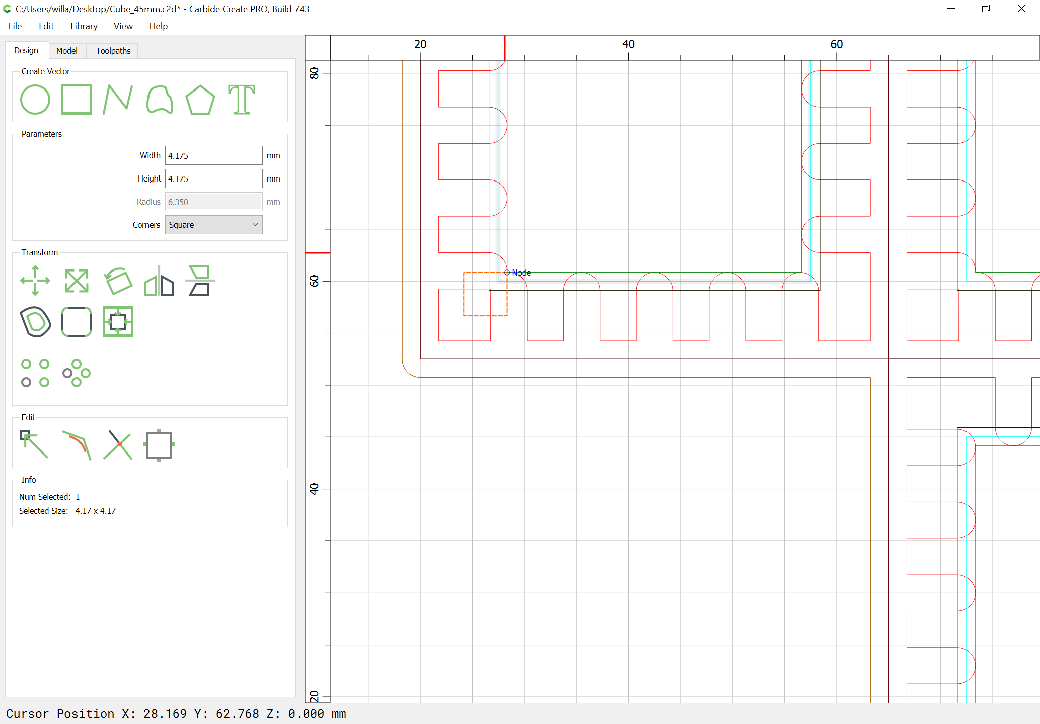
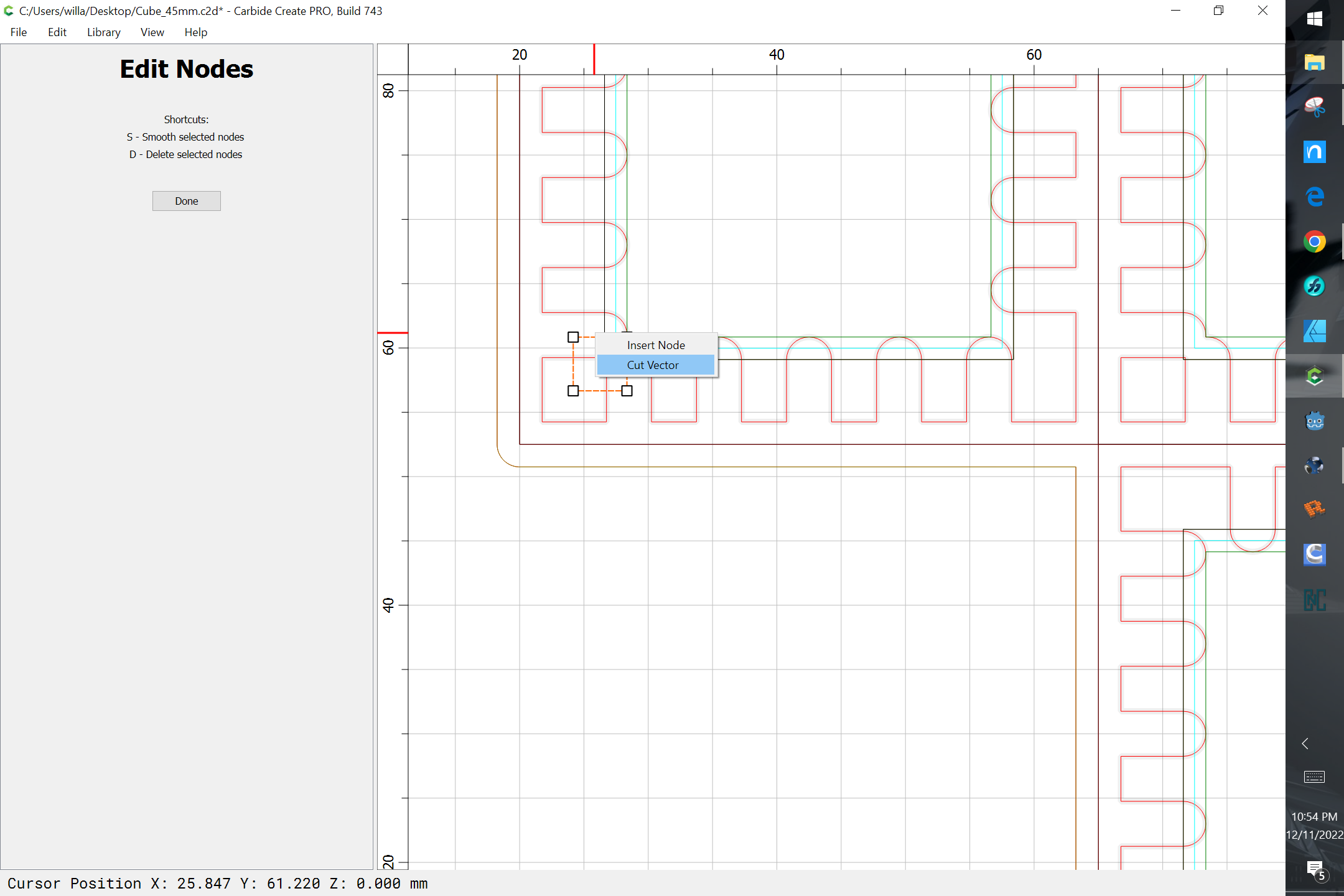
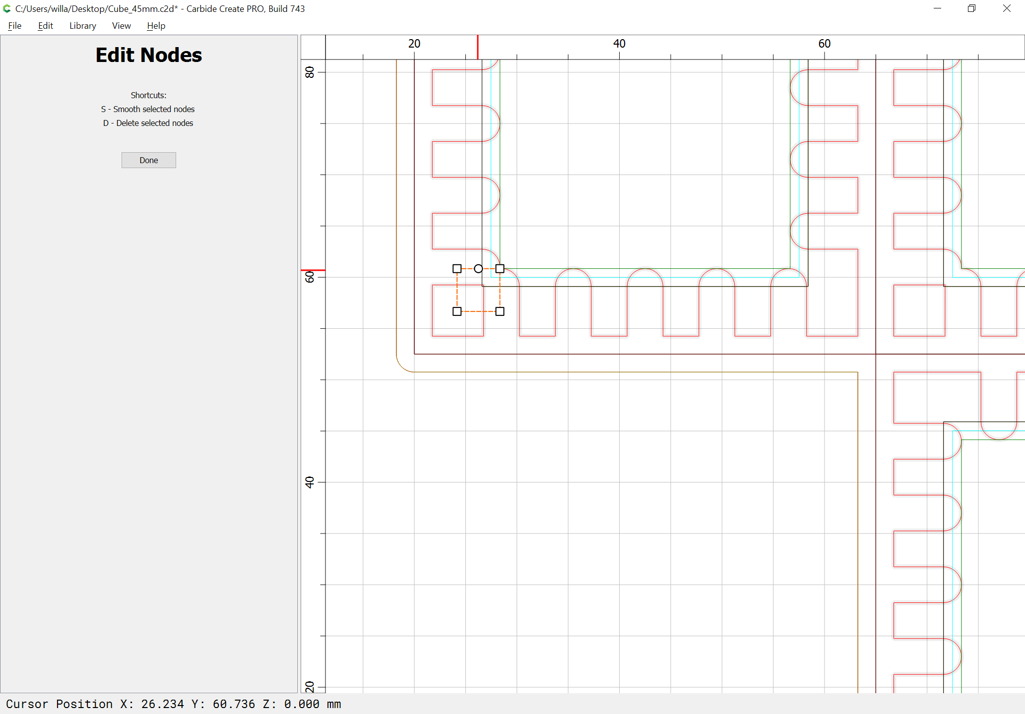
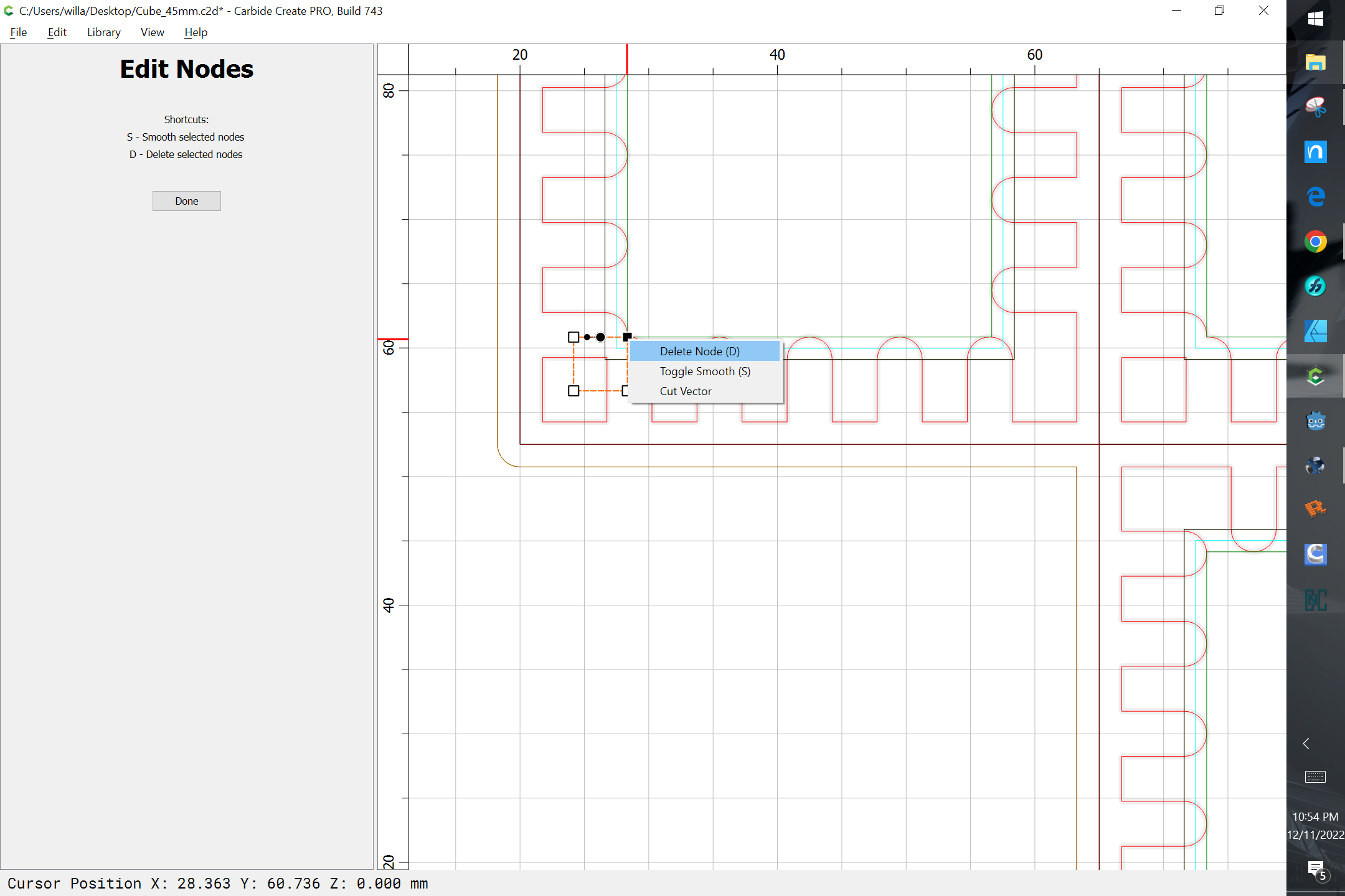
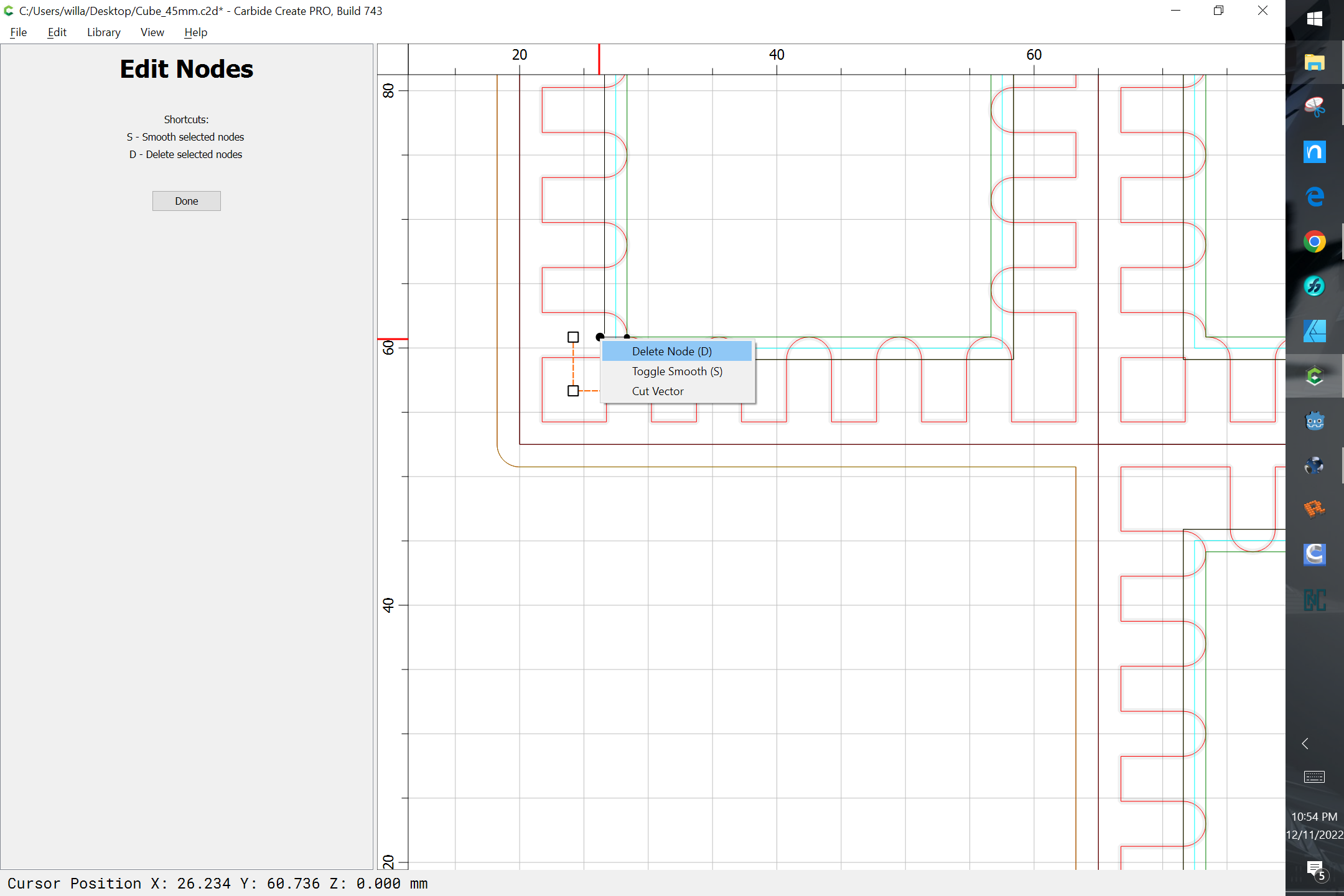
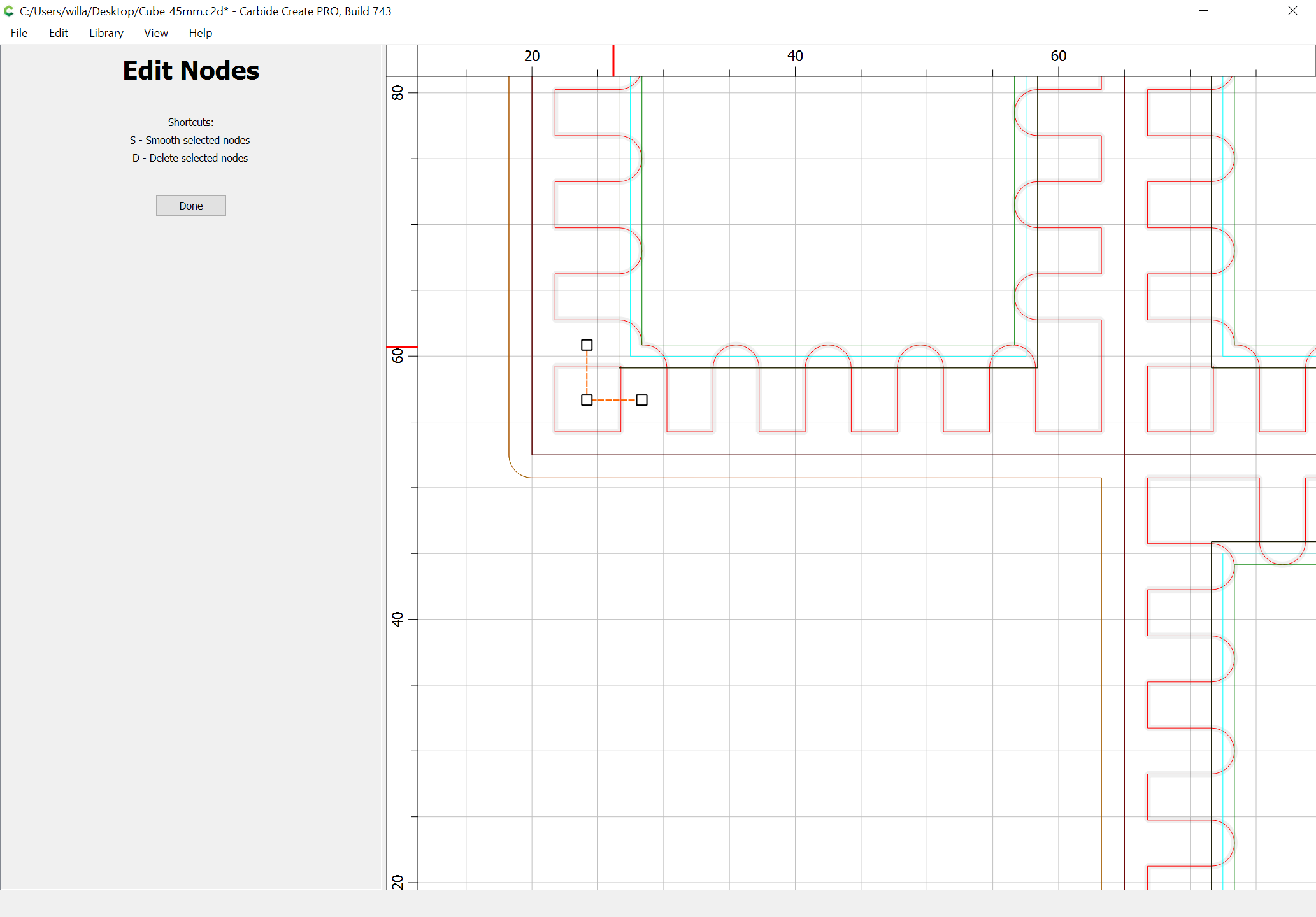
Node edit it to make it into an open polyline:
Then duplicate it in place, select the face rectangle and rotate the duplicate into position, repeating this to get each corner:
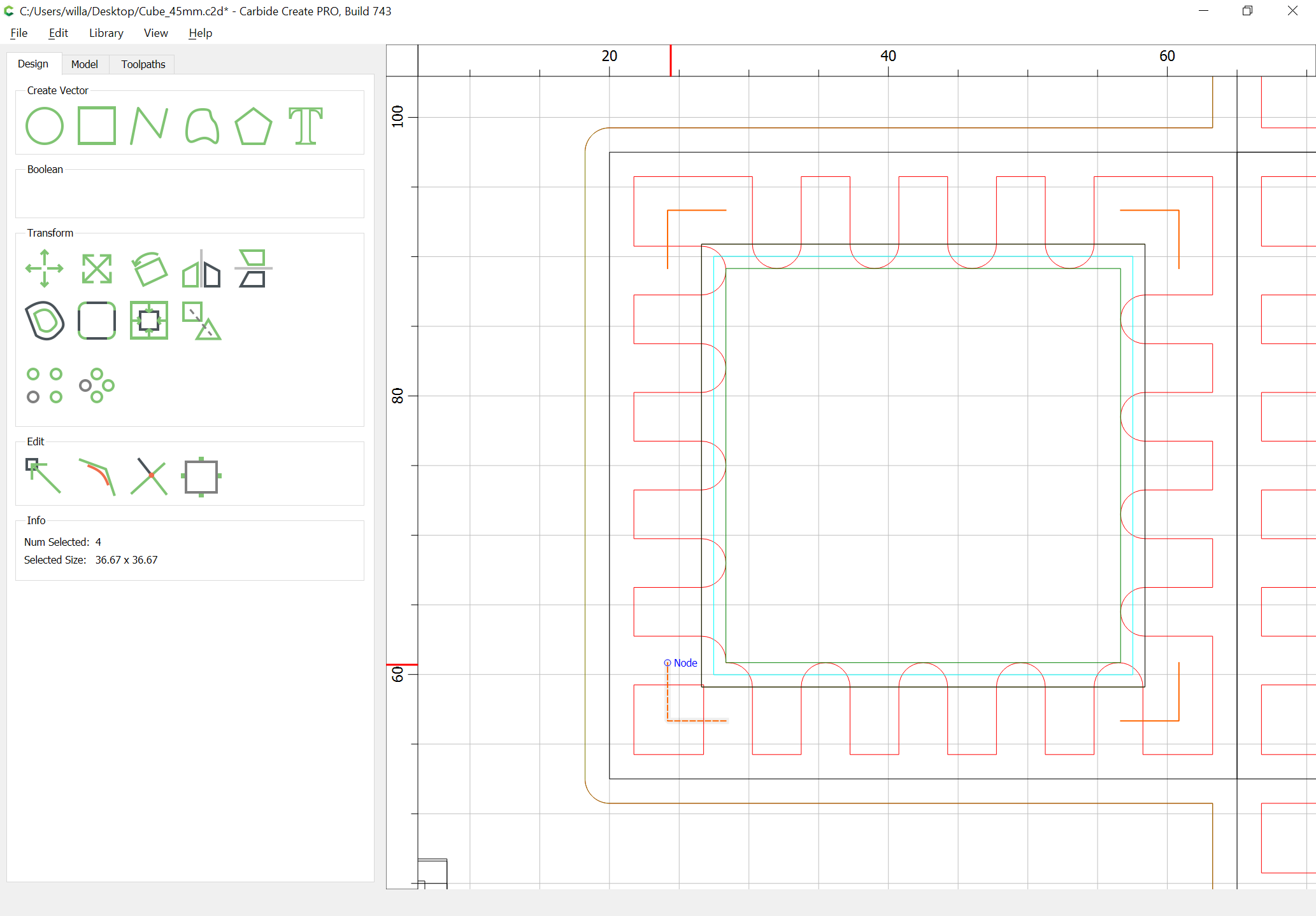
assign a toolpath to an appropriate depth and then duplicate and position for each face and repeat for each other depth/face: