Daughter of Nomad (formerly "Full closed-loop vs. steppers. Worth it?")

I’ve upgraded my stock Nomad as much as I can without making irreversible changes and now I’ve hit the limits, but I still want some of that sweet, sweet rigidity and accuracy, so I’ve decided to allow the Nomad to reproduce. It’s been eyeing some of the Aluminium extrusion residing in its room and I think their offspring would have promise.

The result so far is this:

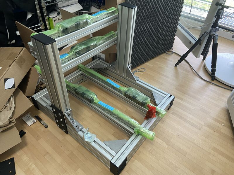
40x80mm extrusions for the square base and for the X-gantry supports, 40x40mm extrusions for the X and Y axes. 25mm linear rails for the X and Y axes and there will be 1605 C5 ballscrews for those as well.

I’m intending to use the current Nomad to square the ends of the extrusions and perhaps flatten them a bit if necessary, as well as to machine some rigid, high-precision joining plates and flat plates to mount the rails to.

But the question I’m asking myself is now that I can, should I try to increase the precision of the machine?

I can buy linear scales with 0.1µm resolution and ±3µm accuracy for ~$120 a piece. I can buy Delta A3 servos + drives + cables for $378 per axis. So I can upgrade to a full closed-loop system (rotary encoder on the shaft, linear scale on the carriage) with 3µm accuracy for ~$500 per axis. It doesn’t even require anything fancy from the controller, since the servo drive can handle the linear encoders. It’s just a really accurate step/dir system. Even GRBL could run this.

But would this actually help, over just using bog-standard steppers?

With steppers, my numbers are:

  • 1605 ballscrews (so 5mm per revolution)
  • ±5% no-load angular accuracy from the stepper itself
  • 200 steps from the stepper
  • So a single step is 5/200 = 0.025mm ±0.00125mm, or 25µm, ±1.25µm. Lets just turn the step resolution into a range and we’ve got total precision of ±13.25µm.

Microstepping is a thing but it’s by no means reliable.

In addition to the steppers, there’s inaccuracy in the ballscrew. I’m using a C5 ballscrew with ~400mm travel, which corresponds to a further ~27µm of inaccuracy.

So with the stepper system, I’m looking at accuracy of ~±40.25µm, or ±0.04025mm, or about ±1.6 thou. Repeatability should be substantially better.

With the servo + scales system, I should be limited by the accuracy of the linear scale and the servo driver’s ability to hug it, so ±3µm plus whatever error the servo driver introduces. I’ve heard that a servo driver can usually stay within around 10 increments, so with a 0.1µm resolution scale, there should be no extra error introduced by the servo.

The scale should also eliminate most mechanical error, like radial/axial play in whichever coupling I use (e.g. a belt reduction on the servo).

The remaining error would be flex in the frame itself. But since I’m using Aluminium extrusions now, it should be relatively simple to reinforce the frame as needed.

Does anyone have any thoughts or comments on whether this might work?

I should add that I don’t need this. At this point my hobby has basically turned into building CNC machines so I’m not looking to actually mill parts with ±3µm tolerances and sell them or anything, I’m just looking to learn about CNC technology and closed-loop motion control. I want to see how far I can get and which barrier I run into (e.g. maybe I’ll have to start water cooling the frame to minimize thermal variance).

I’ll also add that this is more than a little bit off topic but hey, Shapeoko folks might be interested in this since you could potentially add linear scales and servos to a Shapeoko (particularly pro).

Nomad folks might also be interested in using the Nomad to build another CNC machine the way I am.

3 Likes

Very interesting topic, and VERY close to my heart…

BUT First a little background for those who are not familiar with what a Closed and Open Loop system is.

OPEN LOOP: (99.9999 Hobby machines). The computer (GRBL Board) tells the CNC to travel 1.0 Inch (25.4mm), and in turn the stepper motor rotates a particular number of turns to move the Axis 1.0 Inch. IF the timing belt/pulley’s precision is accurate IF the axis does not incur any resistance (cutter friction), OR Objects (e.g. the end mill (bit) hits a clamp) the axis should have gone 1.0" inch.

CLOSED LOOP: The computer (GRBL Board) tells the CNC to travel 1.0 Inch (25.4mm), and in turn the stepper motor rotates a particular number of turns to move the Axis 1.0 Inch. A SECOND system (rotary encoder on the back of the stepper motor OR a linear scale (think digital caliper)) mounted on an axis) provided FEEDBACK to the computer saying YES/NO to the 1.0 Inch move. If YES, the next line in the GCode is read, etc… If NO, the computer continues to move the axis forward (or backwards) until it is at the 1.0 Inch move is satisfied, then it reads the next GCode line. PS: The timing belt/pulley’s precision is NOT needed OR required, since the secondary system (rotary encoder OR a linear scale) is where the precision comes from

My Shapeoko (3) is the first open loop CNC that I have run…at first, I hated the open loop idea, but because of cost, I have learned that like life, there are tradeoffs.

So if you think about it, I now (basically) write programs that allow my open loop system to not miss a step (Stepper motors). Meaning I run my first part and (either) listen for the noise of a stepper motor skip, or look for a scrap part (due to a missed step)…until the cost of a closed loop system can be made. I see that the price of closed loop stepper motors (resolvers) are coming down.

So I (continue) to wait for that day…for the $100 (per axis) close loop system upgrade…a guy can dream…

9 Likes

I’m using the terminology a bit differently so I’ll explain how I’m using it.

Closed-loop (generally): When you tell the machine to do something, the machine checks a sensor to make sure it did it right and keeps checking the sensor to make sure it stays right.

Closed-loop (driver): You tell the driver to move 0.9°. The driver screws with magnets and 0.5ms later, the sensor tells the driver that the shaft has moved 0.84°. The driver then screws with magnets some more and after 1ms total, the sensor tells the driver that the shaft is at 0.9° and the driver knows it can stop bothering.

Full closed-loop: You tell the driver to move 1 step. The driver knows that 1 step = 0.02mm on the moving table. The driver, as above, using the rotary encoder, moves the shaft to say 0.9°. The driver then checks a linear scale to see whether the moving table actually moved 0.02mm. The driver sees that it didn’t and rotates the shaft a little more to get it there.

Open-loop: Who needs verification when you have thoughts and prayers? You tell the stepper driver you want it to rotate 0.9°. It screws with magnets a bit and you hope it did what you wanted (no lost steps, reasonable accuracy). If you aren’t doing something silly, it almost certainly didn’t lose any steps but accuracy is a whole other question.

You can get closed-loop steppers/servos for that price easily. Not full closed-loop with linear scales but a very solid improvement on full open-loop. For example:

If you need scales, they’re an extra $100 or so.

2 Likes

Another thing to consider is what’s achievable in the closed loop feedback system without producing something which has instabilities or oscillations.

For example, correcting for variations in pitch across the length of the ballscrew is something that an external linear scale would provide good feedback to the servo system on and be quite stable. Once tuned to the mass and damping of the attached system you can get pretty good behaviour from even quite simple servo loops.

On the other hand, when you consider the backlash during a direction change attempting to turn the feedback parameters up far enough on a ‘normal’ PID type servo is likely to result in over-corrections and oscillation.

The absolute feedback will help and it can fix things like pitch variation along the length of the screw that motor encoders cannot, but there will be a tuning point where you have the happy medium between ‘responds well and keeps things mostly to target’ and ‘twitches around constantly hunting for a target it can never quite hit’.

2 Likes

I have high hopes for backlash compensation. The Delta catalogue says “To ensure the positioning accuracy at the end and eliminate the effect of transmission backlash, full-closed loop control function is an effective solution”, so I think the intent is that the servo driver compensates for that specifically.

If it doesn’t work out, I can take the linear feedback away from the servo driver and switch to LinuxCNC, which can deal with it more intelligently.

2 Likes

Could someone recommend the most upgraded stepper possible that will work with the Carbide 3d controller for a standard S3 please?

Great,

If they’ve managed to properly incorporate that in their feedback model in the drive it will be interesting to see what it can do.

1 Like

Unfortunately the Carbide Motion board doesn’t really support any upgrades (beyond a few accessories like probes). The first step to upgrading anything electronic on a Carbide 3D machine is replacing the controller with something more flexible.

3 Likes

Yeah,

As Lucas says, there are some steppers which have slightly improved holding torque, there are also some with 8mm shafts which are helpful for going to 15mm belts but the voltage and current limits of the embedded drivers on the Carbide controller board place the real limits.

If you install a ‘higher torque’ stepper you may or may not get that full torque when stationary (holding torque) but this torque drops off rapidly as speed increases (i.e. when your machine is actually cutting things). Higher torque motors tend to need more voltage to achieve torque and so on a low voltage driver like the Carbide board it’s easy to end up with a motor with an apparently higher stall torque that won’t move when stationary but which has lower torque and slips more easily when actually moving and cutting.

2 Likes

It would seem that there are viable servo options in the range of $100 per these days. Most would have an incorporated lead shine drive, software for which is documented well enough. Assumedly adequate for a machine of such construction. I have one on my bench, and it seems to function admirably. For someone as technically capable as yourself, I don’t see any disadvantage, only advanced configurability and performance. Likewise, I recall your quest for silence, the servos I have are all essentially silent. Myself, I enjoy the sounds of a stepper. For the non technical user, I probably wouldn’t recommend them.

Still relatively inexpensive, the Teknic Clearpath line seems very popular for a bolt on step and direction unit. I bought one to play with, its a cool unit and very easy to address. But the likes of the mentioned Delta or DMM AC servos would provide better performance per dollar if the addition of external drives is not a deterrent.

I have purchased a few vintage industrial machines now. These utilize closed loop motion controllers, that feed servo control unit, not as common today, or supported by your typical DIY controllers which I believe tend to be step and direction only(Acorn, Mach, Masso ect). Some neat advantages, such as full servo calibration and diagnostic control within the motion control interface. For instance, each system has the ability to run the axis, identifying tight spots in the rails and variable backlash along the ball screw ect, which can then be compensated for in the controller(anticipatory) or addressed mechanically. Motion is remarkably smooth. One thing to mention regarding the discussion of torque above. Having these systems on my bench for testing, I have learned that they do not necessarily display full torque when they are stationary, locking into position like a stepper. But when presented with a load commensurate with design intent, and tuned appropriately, they are remarkably linear. Something to inquire about when making a purchase.

1 Like

I should probably update this thread: I’ve purchased a Delta servo system:

  • 3x ASD-A3-0431-L drives
  • 3x ECM-A3L-CY0604RS1 motors
  • The various accessories (cables, AC line filter etc.)

400W, more torque than is reasonable and a 24-bit single-turn/16-bit multi-turn absolute encoder.

I’ll wait until they arrive and I play around with them a bit before I decide whether to add linear scales. Could be that C5 ballscrews plus servos is enough.

I spent a lot of time researching all the available options before choosing this particular setup. I looked at:

  • Using closed-loop steppers: no accuracy specifications. Enough said, for me.
  • Using ODrive or IONI plus an encoder to make a servo drive:
    • Stand-alone high-resolution encoders are expensive. By the time you add an encoder to the ODrive or something, you’ve basically got the same cost as ordering brand-name servos and drives. I did find one $80 encoder but the idea of using it with ODrive just didn’t work out. I have a whole thread on this here.
    • Stand-alone encoders have physical mounting requirements that don’t always fit well with other motors. The one I found requires a tapped thread on the end of the shaft it mounts to.
    • IONI requires unusual low-voltage servo motors which are difficult to obtain.
    • ODrive is built for ridiculously high power which wouldn’t work well on a CNC of this size.
  • As above but with a commercial servo motor: financially might work but the commercial motors don’t use open protocols, they do their own proprietary thing.
  • Various other brands of servo motor (Yaskawa, Mitsubishi, Panasonic etc.): they work and seem reasonable but Delta had the best price performance and availability.

One particular bonus of the higher-end servo drives is that they have native support for linear scales. You just hook up the scale and tell the drive what multiplier it uses and you’re good to go: you just feed it the same step/dir signals as usual and it moves like a stepper would but more accurate. No need for fancy LinuxCNC controllers with extra feedback loops or anything.

3 Likes

You should update us on how it goes. This sounds very cool.

2 Likes

I think you have a (ball) screw loose… and I love it! Seriously I have nothing but respect and love for what you are attempting. I personally love modding things and augmenting things. I completely understand the drive to want to make your machine better. This is why I have the BLDC spindle and switched out my controller for a Duet. I am all for learning CNCing and closed loop control. It is something I am thinking about for the future of my machine, once the Duet has better support for ODrives.

That said, I do not think the frame you are putting together will be able to support the level of precision you are going for. There is a reason why high precision milling machines are huge heavy blocks of thick cast iron. They are rigid and resist oscillations. Even using the thick frame members you have selected. Even with reinforcing them where ever possible. It will still flex. It will still oscillate. You are going to get chatter. It does not matter that you will be able to position the end mill to within 1um. That end mill is still going to be bouncing around. So unless you plan on having teeny tiny chip loads all this precision is going to go to waste.

Personally I suggest looking into taking a small manual mill and converting it to closed loop control. You could use many if not all of the parts you have purchased for that. The guys over at Physics Anonymous have been doing something similar.

3 Likes

I get the desire but I’d have a look at the discussion I had with the ODrive folks. The conclusion I came to is that the ODrive just doesn’t make sense for driving our linear axes. It’s much too powerful and requires crazy high power (expensive in Europe) power supplies, which eliminates most of the cost benefit over servos.

Maybe v4 will make it more workable though…

I know I’m not going to work any magic here. For the heavy cuts, I just want less chatter, I know it’s not going to be perfect. I just want to be able to do some basic shoulder milling and push the spindle closer to its 800W capacity. Where I want the precision is on the light finishing passes. There’ll be negligible cutting forces there so I still have some hope.

And I know so, so very clearly, that I’d be better off with a better base for the machine. If I could, I’d buy a second-hand VMC or Syil but I’m still stuck in the same apartment that led me to buy a benchtop CNC in the first place so I have to make do with what I have. Despite the size of the new frame, it’s still light enough to fit well within the specified load of my IKEA standing desk.

But if it ends up being necessary in the end, I’m already eyeing a new frame. Nothing like a 220kg hunk of Russian epoxy granite if you’re after rigidity… By the time I get around to it, hopefully I’ll have moved into a larger space.

1 Like

Provided your mechanics can handle the rate of motion, which I’d think wouldn’t be too hard on a machine this size, a high speed spindle might be a nice solution. Fun to watch too.

1 Like

I’ve already got 30k RPM but I have been thinking of going to 60k if/when I buy a new one with a toolchanger.

1 Like

I filled my rails with epoxy and sandblasting garnett (just to eke out a little more density over regular sand) to add mass and dampening. Added about 50lbs or 25kg to the system. No noticed ill effects on the motion system yet. Steppers are fine. V wheels got a flat spot after leaving the machine sit a month, but that fixed itself after running a bit.

2 Likes

Where did you source your drives and motors?

Were you able to measure any differences?

These guys: Guangxi Nanning Craftsman Electromechanical Equipment Co., Ltd., but the servos haven’t arrived yet so I can’t make any recommendations.

FWIW, I paid $1451 total:

  • $192 per drive ($576 total)
  • $166 per motor ($498 total)
  • $246 FedEx shipping
  • $130 for various cables

And the service so far has been pretty decent. Some sellers don’t want to talk about anything but taking your money, the sales person I’ve been talking to was friendly and was able to help me figure out what to do with line filters and answer all my questions about customs and shipping.

Sorry , Lucas, but I can’t speak to that as I failed to gather hard data that would be applicable. I also added an HDZ and SMW fixture plate in the same build which would complicate isolating the effect. At the time, I was figuring it was a directionally correct move to make and didn’t bother. Subjectively the pitch of noise the machine makes while moving and cutting seems more muted/softened now.

What kind of testing would quantify the improvement do you think?

1 Like