I’m trying to produce this raised surface on the face of two sides of a triangular shaped piece of wood. The raised surface should be on the centerline of the face.
When I run the simulation in fusion, it’s great.
When I run the program on the shapeoko, the raised feature is shifted off the centerline and almost at the positive Y edge (see drawing here. Link )
When the shapeoko starts, it cuts down the y axis, going beyond the width of the triangle, cutting air as it travels down a line parallel to the X axis. It then moves parallel to the y axis in negative direction, and then turns to move -x direction still cutting the top of the triangle face.
The end result as I said is that the raised feature is not on the centerline face as shown in the drawing, but almost as far in the Y direction that it can be and still be on the face of the triangle.
I set zero using a piece of paper, setting all three axes.
I had similar results with the first project I created. I honestly don’t remember how I was able to resolve the issue but it was similar in that I cut a lot of air on one side of the project.
Anyway, I cannot find any documentation or any other help on what to do. I’m hoping you all can help.
I’m using shapeoko 3 XL with latest carbide motion software.
Usually when the simulation and reality don’t match, it ends up being that
a) the dimensions of the stock declared in Fusion did not quite match the actual stock
or b) the zero reference in the Fusion file does not match where/how you zero on the stock.
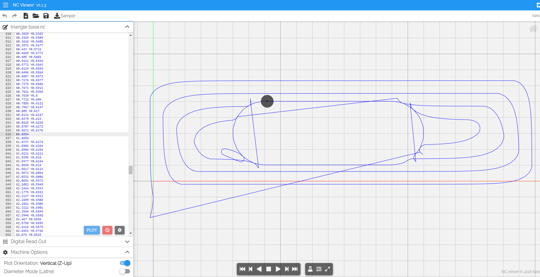
Because I was not sure how a single program would behave, I split the machining of the two triangle faces into two separate NC files. Triangle base is the name of the file that cuts first.
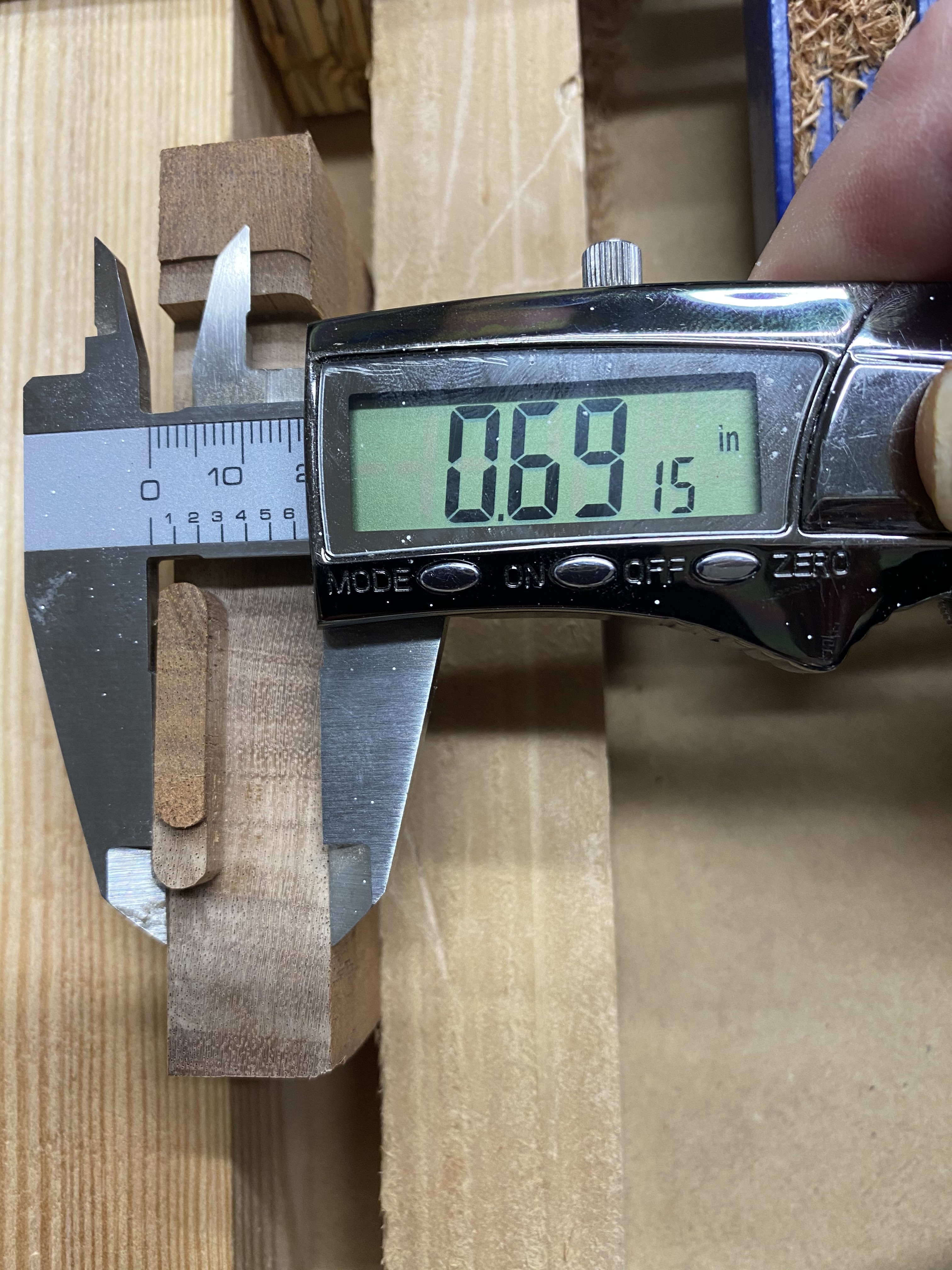
I was cutting the raised feature on a piece of scrap wood which is not quite as thick as my actual stock to be used once I know the setup is correct.
The actual stock would be .765 inches. The scrap stock is .739 inches. (is that too much of a difference?)
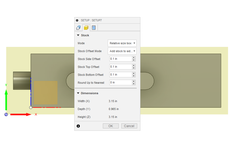
I did add a stock offset of 0.1 inches on sides, top and bottom.
Thanks. I can’t download the Fusion file, I think this has to do with the recent updates which deny hobbyists the capability to share links (sigh…)
Can you go in File / Export and create a .f3d file ? (or have they removed that too…)
I took a look at the generated G-code for the base,
and from that file I see that the top part of the raised feature should be 0.6276 - tool radius = 0.5026 from where you zeroed, along Y. If the bottom of your stock is still uncut can you check that ?
The middle of the raised feature is at Y=0.3776 in that file, so the cut will work (ie. have the raised part along the centerline) only if your stock is exactly 0.755 wide (which it is not? but that should not result in the raised part being completely shifted to the top either)
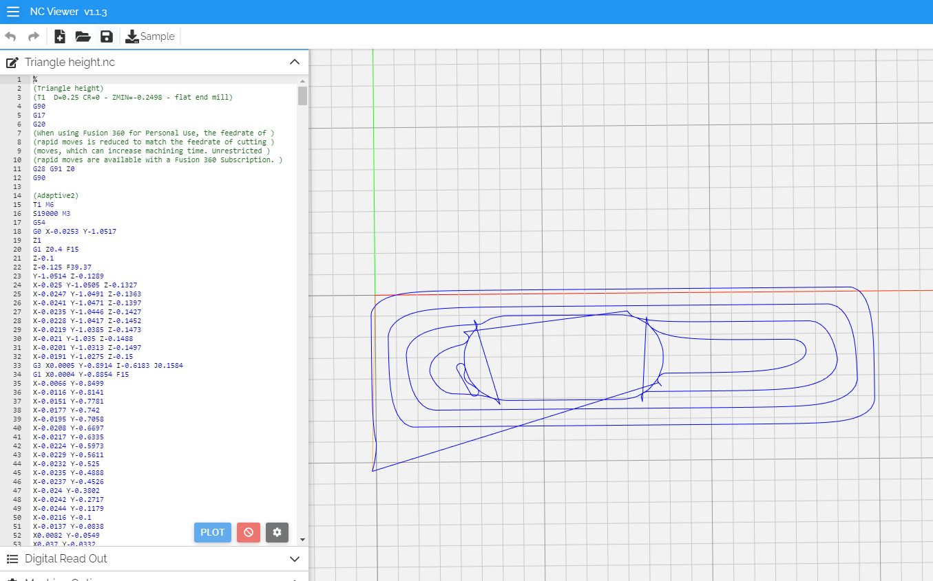
On a side note, the other G-code file has the cut on the opposite side of the Y0, just mentioning it in case this is not intentional:
an .f3d file was not an authorized upload file type here so I zipped it in order to be able to upload here.
I’ll take a look at your post. I agree that not having the exact width scrap will offset the raised feature from centerline, I was thinking, like you, that it would not be the reason that the raised feature is so far off the centerline. let me study the rest of your post.
hmm.
I set zero on x,y and z using a piece of paper. For x and y, I accounted for offset by adding an additional 1/10th of an inch. so if x at piece of paper was for example 0.23, I subtracted 0.1. Then I added .125 for the radius of the end mill. After similarly doing Y, then z, I set z to zero while touching the paper. Then I moved z up. Moved spindle to the calculated values (adjusted for radius and offset) for x and y. Then set zero for x and y. Make sense ? was any of that incorrect?
I just went through the fusion design and changed the thickness dimension to that of my scrap stock. I removed all offset from the stock.
I made the cut called for by the triangle base code and the raised feature was close to centerline. The side of the raised feature that is farthest from zero is about .05 closer to that face edge than the opposite side of the feature is to that face’s edge. It’s enough to be noticeable to they eye.
Sounds like coordinates/origin issue to me. The default in Fusion360 is “centered” for the position of the part vs. the stock. This is sometimes convenient, but it’s surprised me on numerous occasions just how “off” this is when I think "well, what I told Fusion the stock is, and what I have in my hand aren’t that different.
For entertainment and simplifying this (it’s framed as a software issue, but we haven’t ruled out the more likely hypothesis that it’s doing exactly what you told it, you just don’t know what you told it), could you:
don’t use the relative size stock; measure your exact stock and use the exact method instead
offset from -x and -y such that you know you are not relying on any relative placement of the part within the stock
redo your paper offset method (with the assumption you’re remembering to remove 1/2 the cutter width
after doing this, move up in z and use CM to actually rapid to “current xy offset” to know that your origin is what you think it is
Thank you all for the help. I changed the stock offset to zero and used actual scrap stock thickness instead of real part thickness. With all that done (and I accounted for 1/2 the bit diameter) it was off by about .05 inches.
What I’ve learned today is that a few thousands of an inch can matter. I also was confused because fusion was sending a g54 code in every nc file that it posts. I wasn’t sure how shapeoko was handling that and wanted to rule that out. Today’s results tell me that it’s not G54 or at least a bigger source of error is my setup.
In essence I have tested CM rapid move to x and y zero. I was milling another project this afternoon and did just that to see if zero was where I thought it should be.
I’m sure there’s more you all can teach me. I need to fix the things here I’ve learned today.
Results:
Square 5.0105 x 4.995 x 5.02 x 5.000
Diamond: 2.8545 x 2.8755 x 2.8565 x 2.872
circle: 2.26 to 2.29 inches (just rotating the calipers around it)
Open to feedback /comments on what I need to work on/ adjust.
is there an image that goes with that discussion? it talks about creating three right triangles and then discusses measuring holes. I think I got lost in it.
In case it helps, my take on belt calibration is described in this section of the ebook, it has one pic to illustrate. But basically it boils down to “cut something of length L, measure how long it actually turned out to be on the machine, then adjust $100, $101, $102 accordingly to compensate”