As noted, above, you seem to be selecting all of the geometry for the 3D toolpaths.
I saw that comment about the offset around the box and deleted it. What I didn’t see or remember was the offset around the shell outline, which I have not deleted and it seems much better.
Sorry for my failure to see the problem but appreciate the guidance.
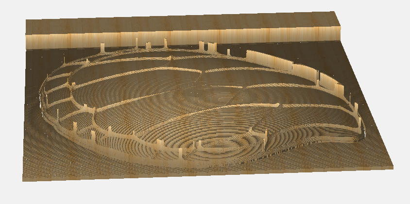
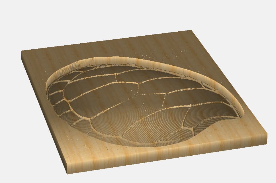
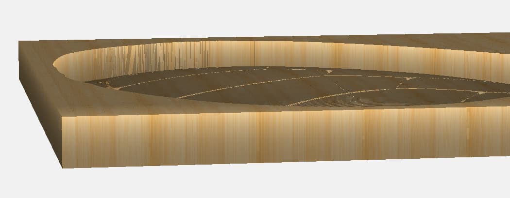
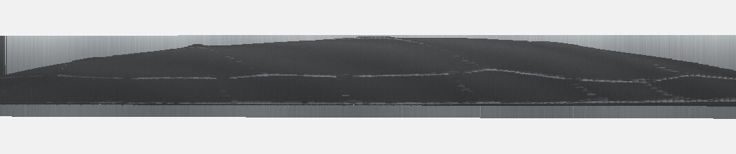
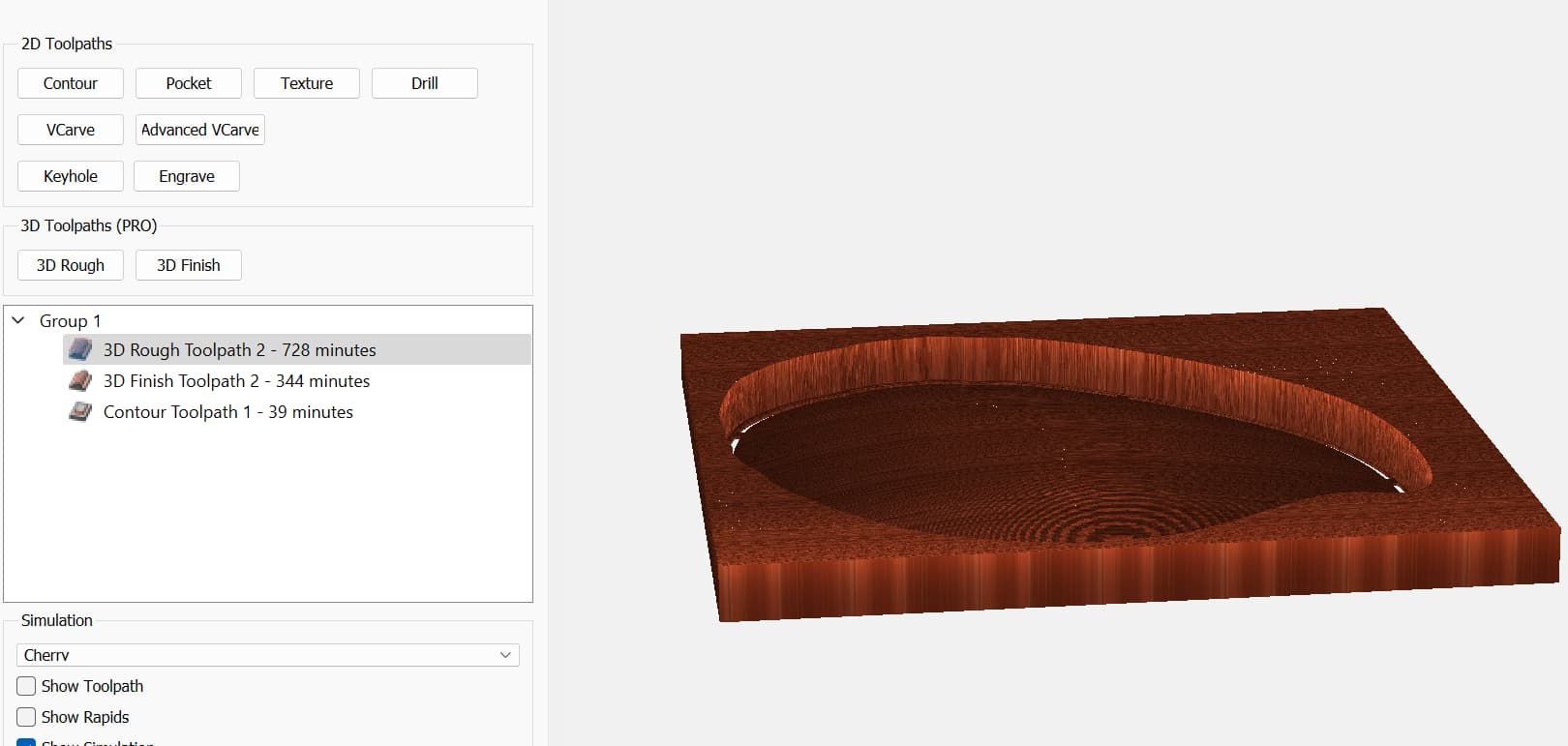
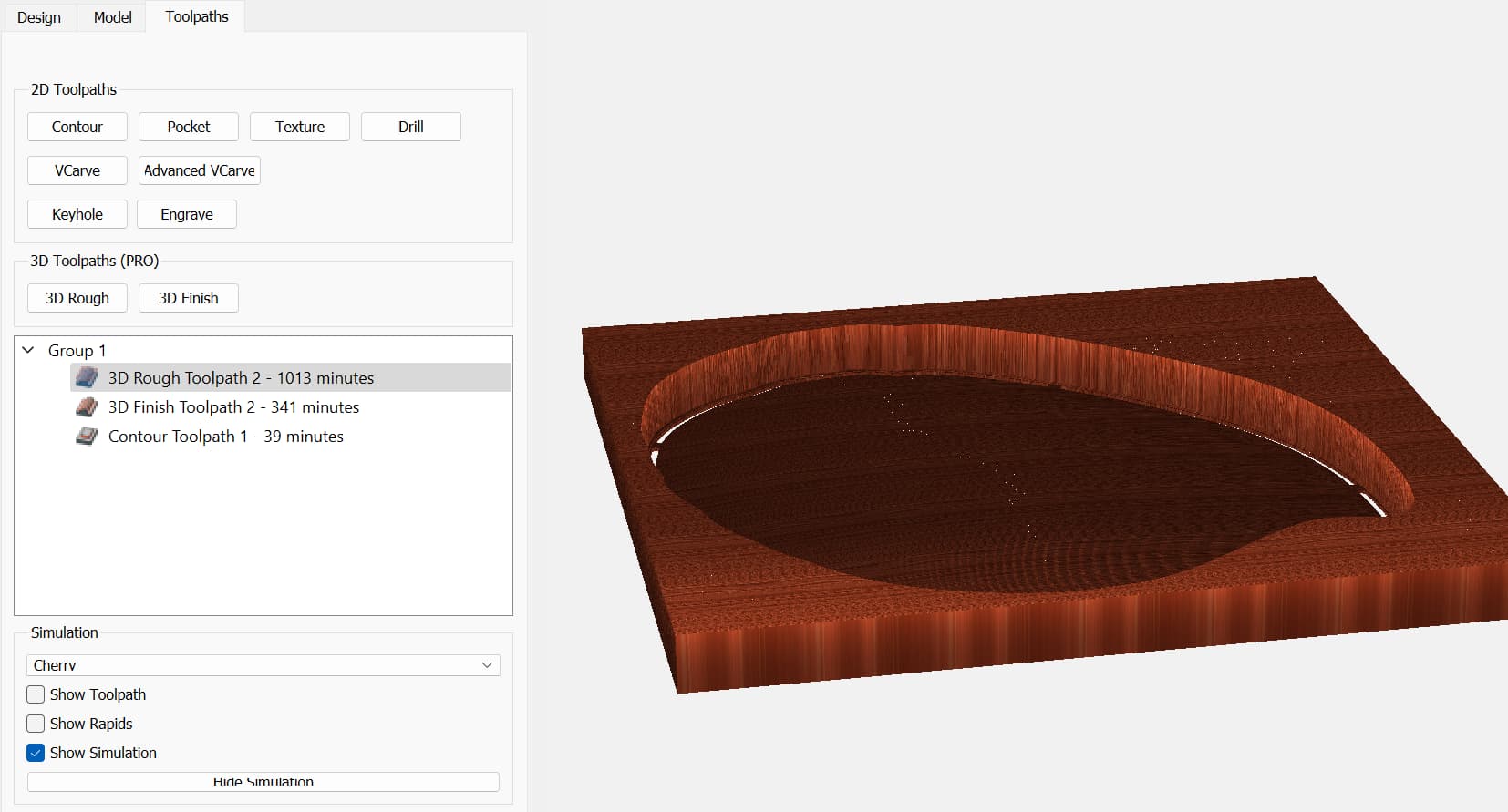
The final simulation does show some strange “tailings” sticking up. See below. Any idea why those remain?
What geometry is associated w/ the 3D finishing toolpath?
It should be a geometry which surrounds everything which you wish to cut.
As noted before, the geometry used in the screengrabs I posted was:
If there were gaps in it:
The area of that gap would not be included/considered for the 3D toolpath:
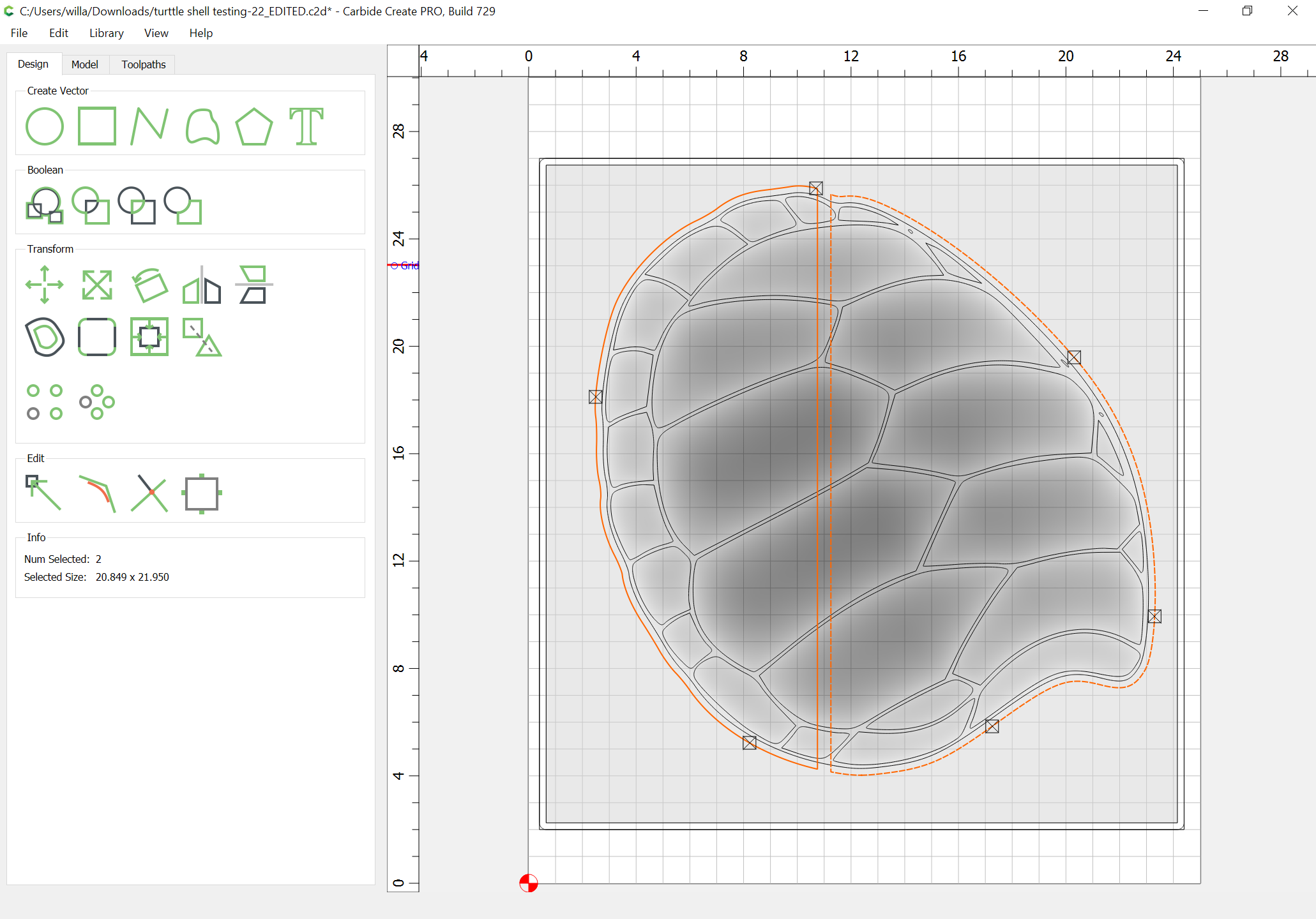
If you select everything:
then the areas in-between what you selected won’t be cut:

I made a YouTube video on how I made a turtle shell / box. Search Stephen k cox turtle.
I think I finally have it! Hurray!!
Now will see if I can get some ball cutters and actually cut it out.
THANKS for all the help AND patience with me on this.
I have both Cherry and Black Walnut to see what looks the best. Will post the results when we get there!
Your Shell Back component should be a Subtract, rather than an Add
You are correct if the area between the plates should be “indented”, but there are some, such as here in SC, that have ridges. Thanks for the idea of how to do either.

1 Like
Fair enough. The sharpness of the ridges made me assume they were supposed to be indented rather than raised.
Back again for more advice.
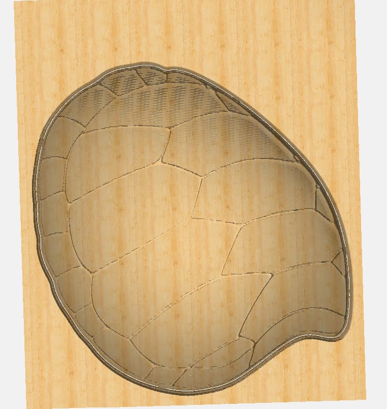
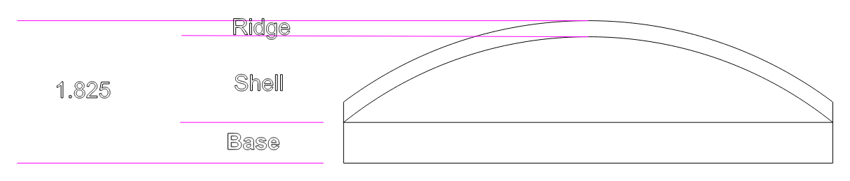
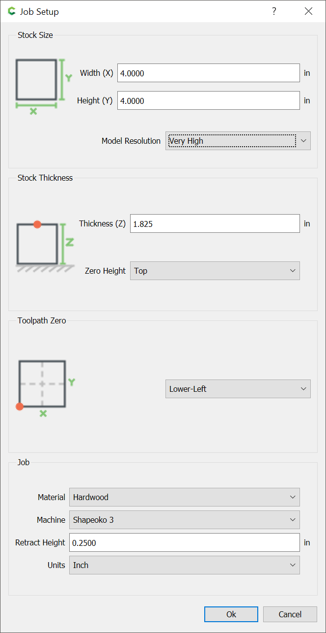
In the attached pic., I would like to keep the turtle as thick as possible but while I have adjusted the model setting heights up and down, it doesn’t seem to get the top of the turtle close to the top thickness of the board, which has a thickness setting for the material at 1.825 inches.
Anyone know how to make the top surface of the turtle back and the board come closer together…ie almost level?
Use the Scale Height option as was shown above.
Do the math… ![]()
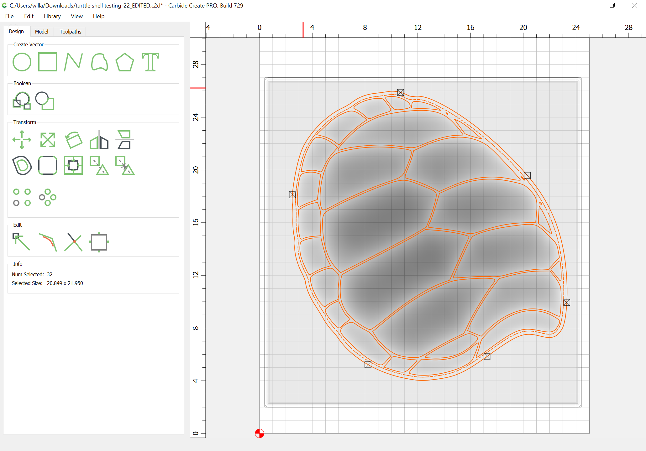
OK, I looked at your file. A couple things… In Job Setup, set your thickness to 1.825
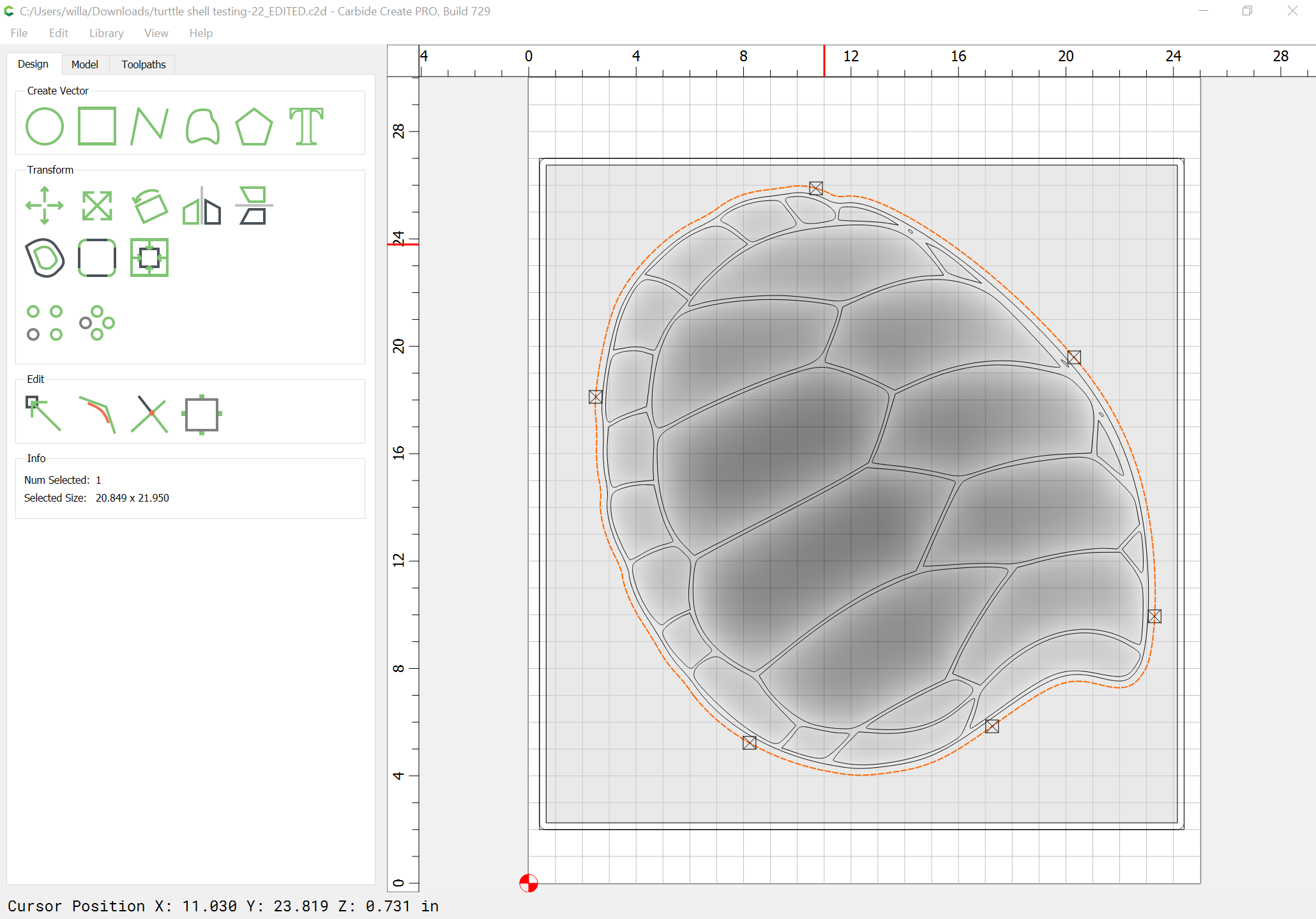
For your toolpaths, you have 35 vectors selected. It should be 1. The outside rectangle, or an offset from the outer shell boundary.
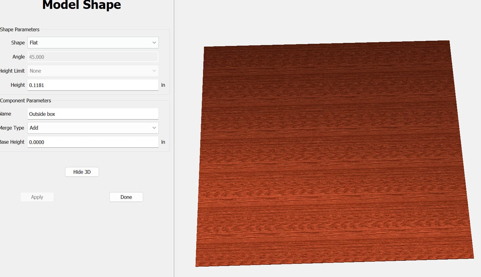
I set those things, rebuilt the model using
Base: 0.25", flat, Add;
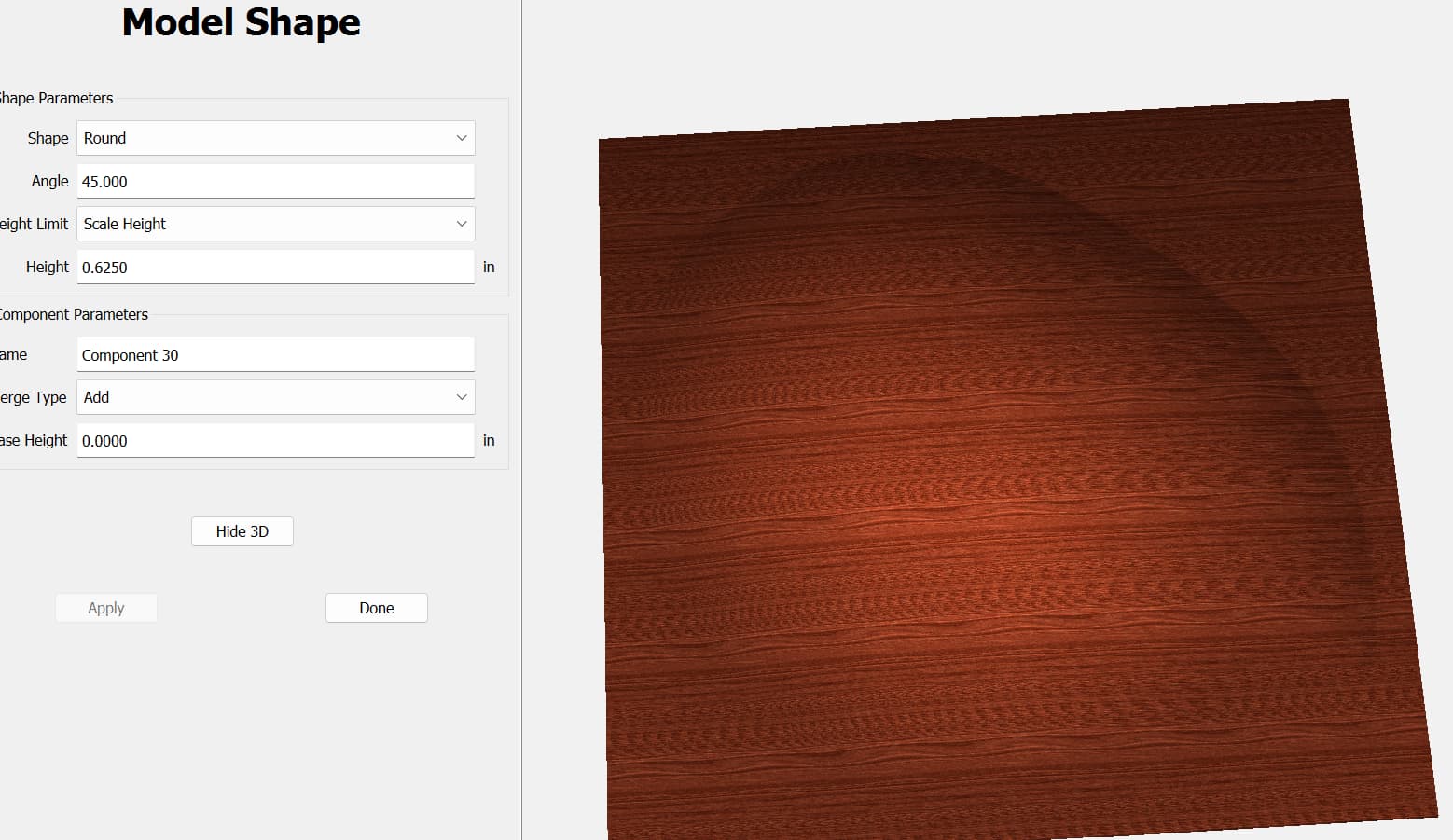
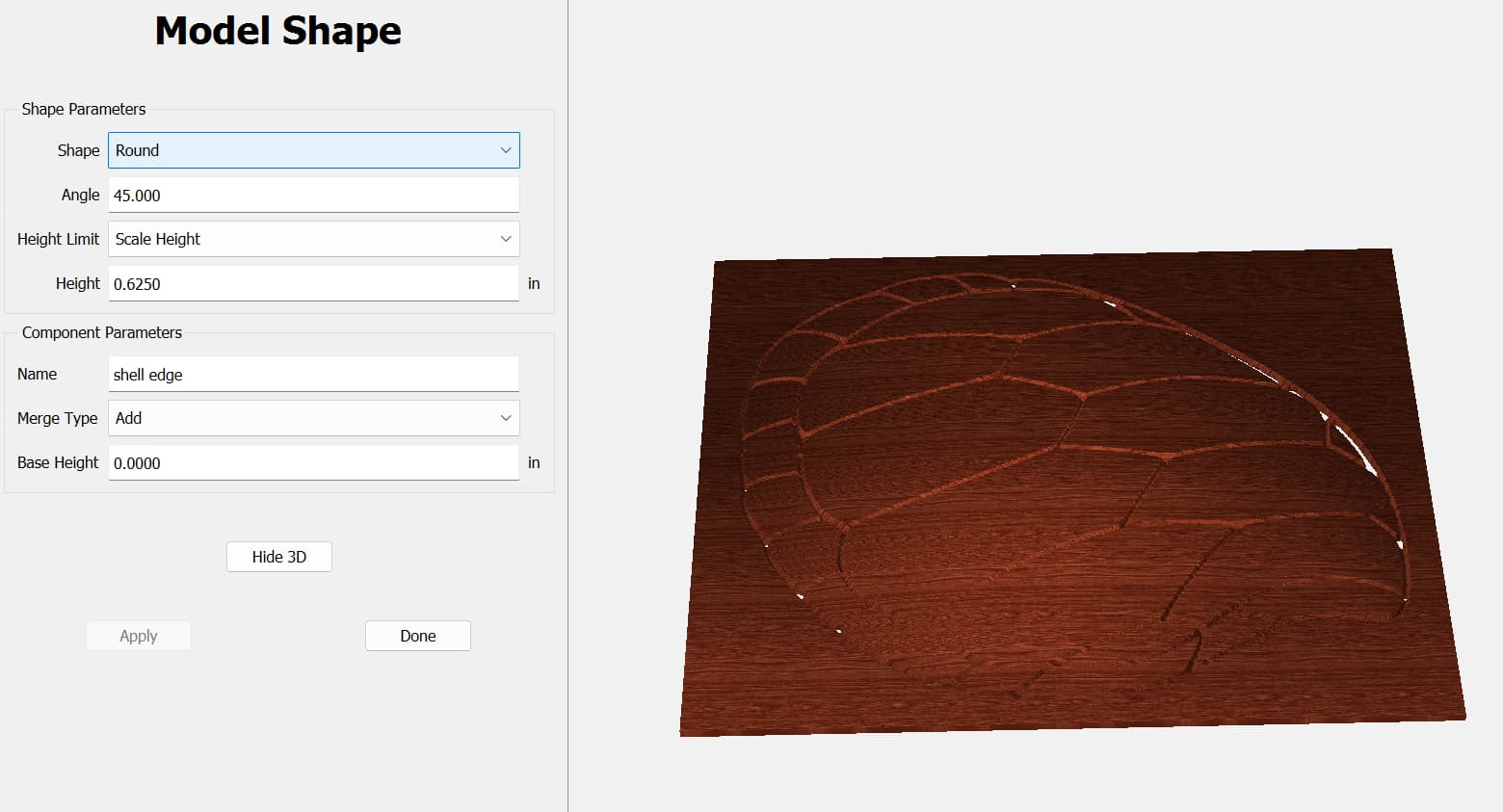
Shell: Round, 45°, Scale height, 1.450", Add
Ridges: Round, 90°, Scale height 0.125, Add
I stretched the rectangle off the left side so it cuts out the left wall & I could compare the heights
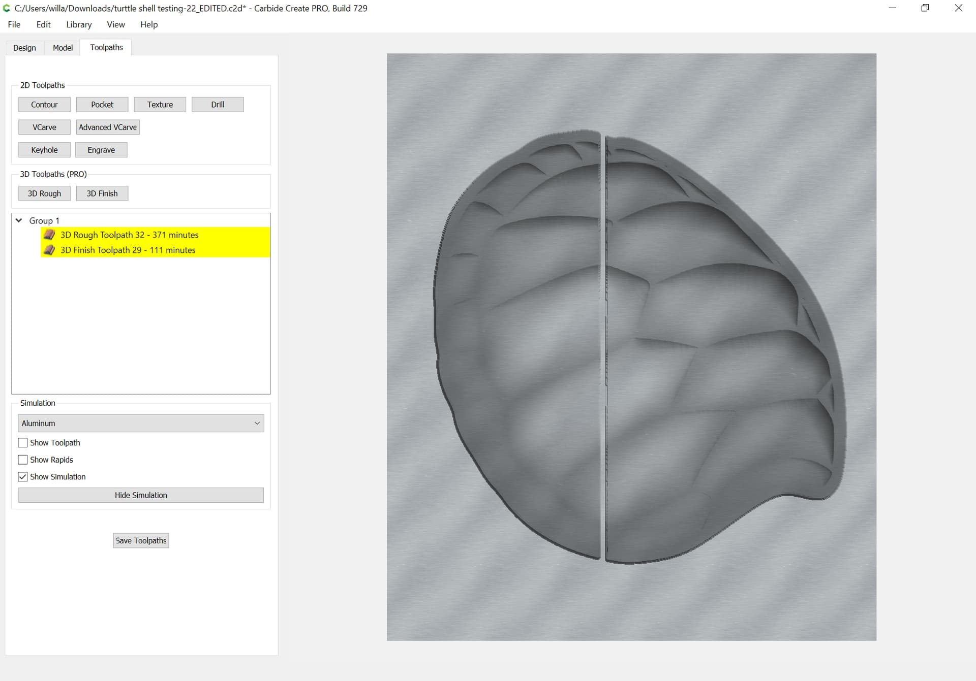
Looks like it’s right there! ![]()
P.S. Perspective view… I don’t wuv it!!! Orthographic views is where it’s at ![]()
I guess I’m just a dumb rock, and I’m sure all those who have done 3D work are have a great time enjoying my work and lack of intelligence.
Obviously, I’m getting very frustrated and I haven’t even made it to the first actual cut attempt. ![]()
Tod:
one plus one = 2
Got it! ![]()
Thus the base height in ALL setting is 0.000
Therefore, changing the Shell thickness should render the Ridge height right? No change??
Is there a RIDGE setting I’m missing somewhere?
I’ve tried changing the Toolpath for the Rough cut depth - no help
I’ve tried changing the Model for the box up and down - no help
I’ve tried changing the Model for the outline of the turtle shell - up and down - no help
I’ve tried changing the Model for the shell back of the turtle shell up and down - no help
I’m using the scaled height in both the shell edge and shell back
I have changed every setting in every place I can see, but nothing seems to get up to the surface of the material.


Part of my frustration comes from the problem of not being able to go back and see what you entered into the Model setting after you go to check the Tooling setting.
When you go back to Edit the Model setting on a given component, not all the parameters show up and thus you have to use pencil and paper to write down the parameters and then delete that component and redo from scratch. Lots of time, effort and frustration when you can’t just go back and change the height or angle or shape.
Just takes a lot of time to keep deleting and redoing over and over to try and find where the changes need to take place.
Why not try “Scale Height” and setting the Height to Stock thickness less any underlying model thickness less any additional features you will be adding?
One thing I did when starting out was to fill in the component name w/ the details of the model — that allowed for re-creating elements w/ variations in the settings.
Nope, the 3D interface / workflow is just freakin’ weird!! It’s all based on image editing, NOT traditional modeling.
My bad using “base” as a descriptive. I was referring to the bottom layer of the model, not the “Base Height” setting. Base Height just adds a flat pedestal of that height below the component you define.
Otherward, it extrudes the vector straight downward under the shape. I think you can leave Base Height at 0.0 for your components.
And yes, the fact that the components aren’t fully editable is really frustrating.
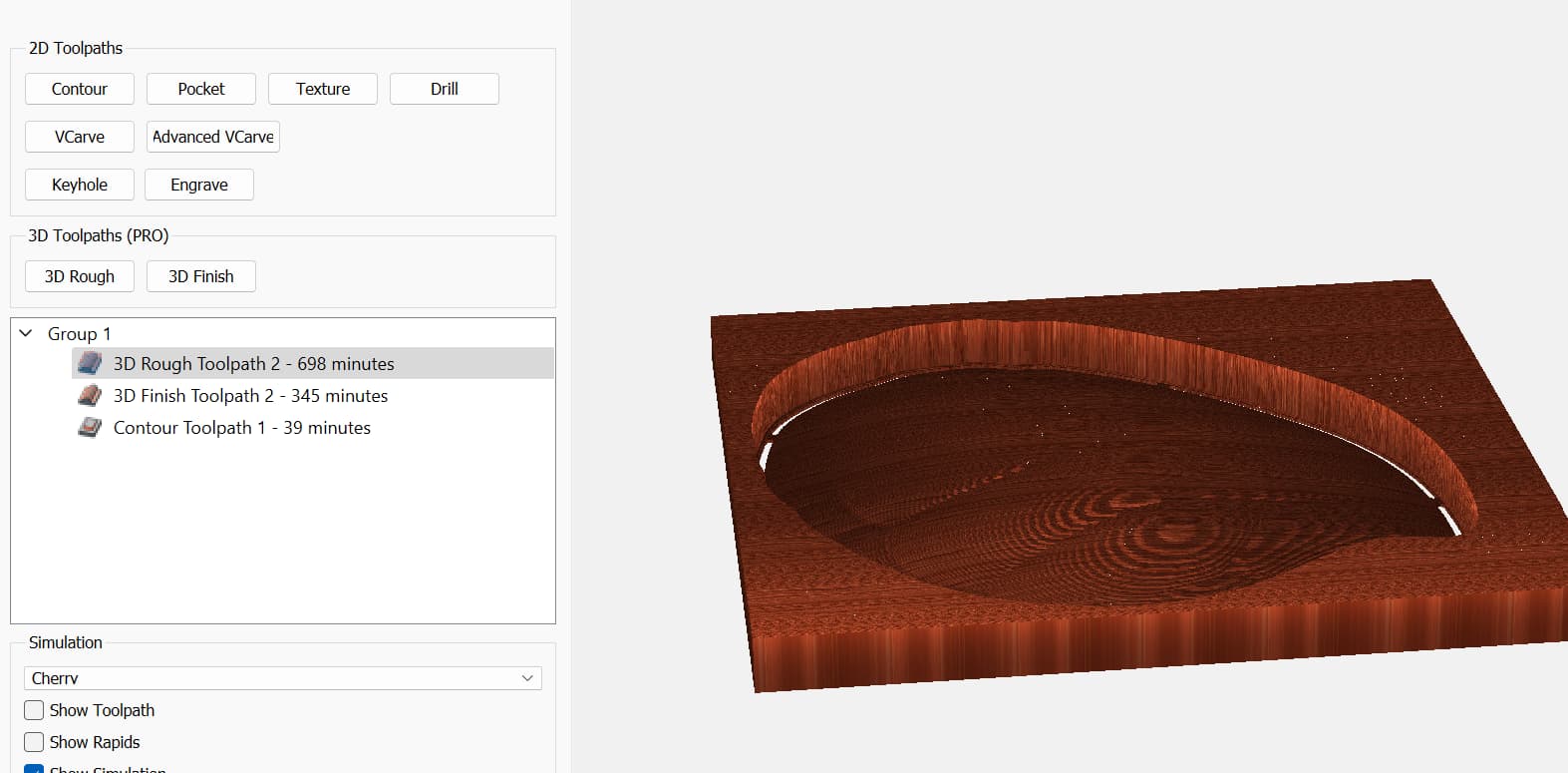
I’m seeing a bunch of different heights in your images. 0.3, 0.125, 1.5, 0.625, 0.1181, 0.055…
Is the “Math” drawing I made correct? You want 3 components (bottom, shell, ridges) that add up to 1.825" tall? (except I think the bottom extends out to the edges of the rectangle, right?)
What heights do you want the components?
First off…do you guys ever slept! I’m impressed. ![]()
Will: I’ve started doing the name field as you indicate. It does help, but one you delete it, you better have written it down or for an old guy like me, may be lost to the air. ![]()
What I’m trying to do is both get the most “height” of the shell back as possible and reduce the time to cut to a min.
As such, the material is 1.875" and thus would try to get the highest point of the shell back to be somewhere close to that number.
I set the material thickness to 1.875"
Set the outline box thickness to 0.25"
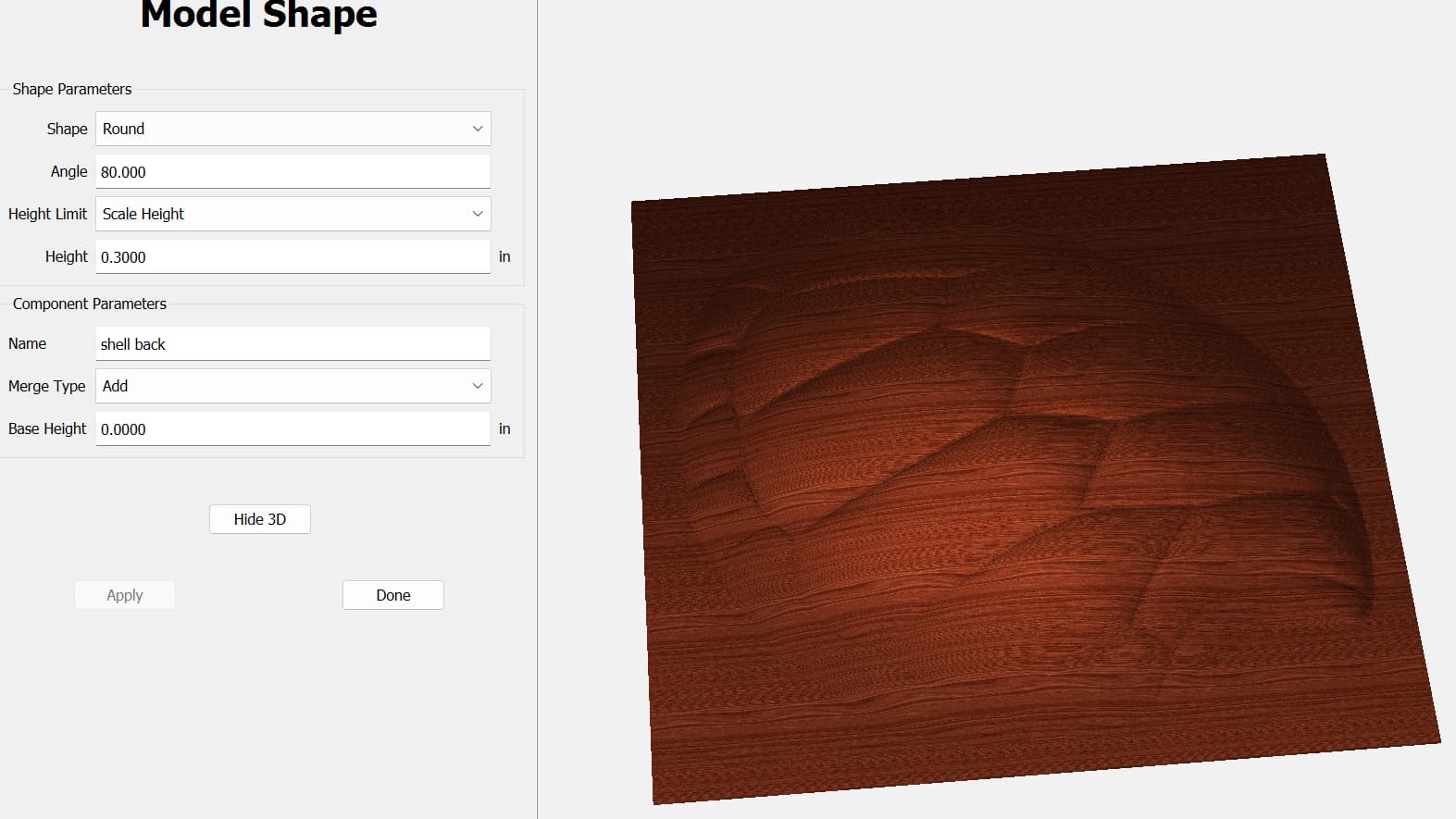
Set the outline of the shell to ROUND, with HEIGHT between 0.1 to 1.5" in varying increments but nothing changes (also with SCALE)
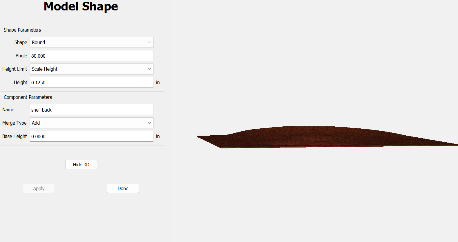
Set the actual Shell back to ROUND/ANGLE at 80 down to 30; Scaled; HEIGHT between 0.125 down to 0.1 and up to 0.5
None of these seem to change the actual height of the shell back. I did see that if I change the ANGLE it does get the back ABOVE the material thickness in the SHOW 3D, but does not change in the Tooling simulation?? Weird for sure.
I’m sure there is some combo that I’m missing but there must be at least:
7000+ combinations to try.
Sooooo, I’ll keep trying and see if I can get there sooner or later.
If you model past the stock thickness, the excess will be shown in red in the 3D model view (to indicate the error), but won’t show in 3D toolpath view (since it extends past the stock and doesn’t really exist).
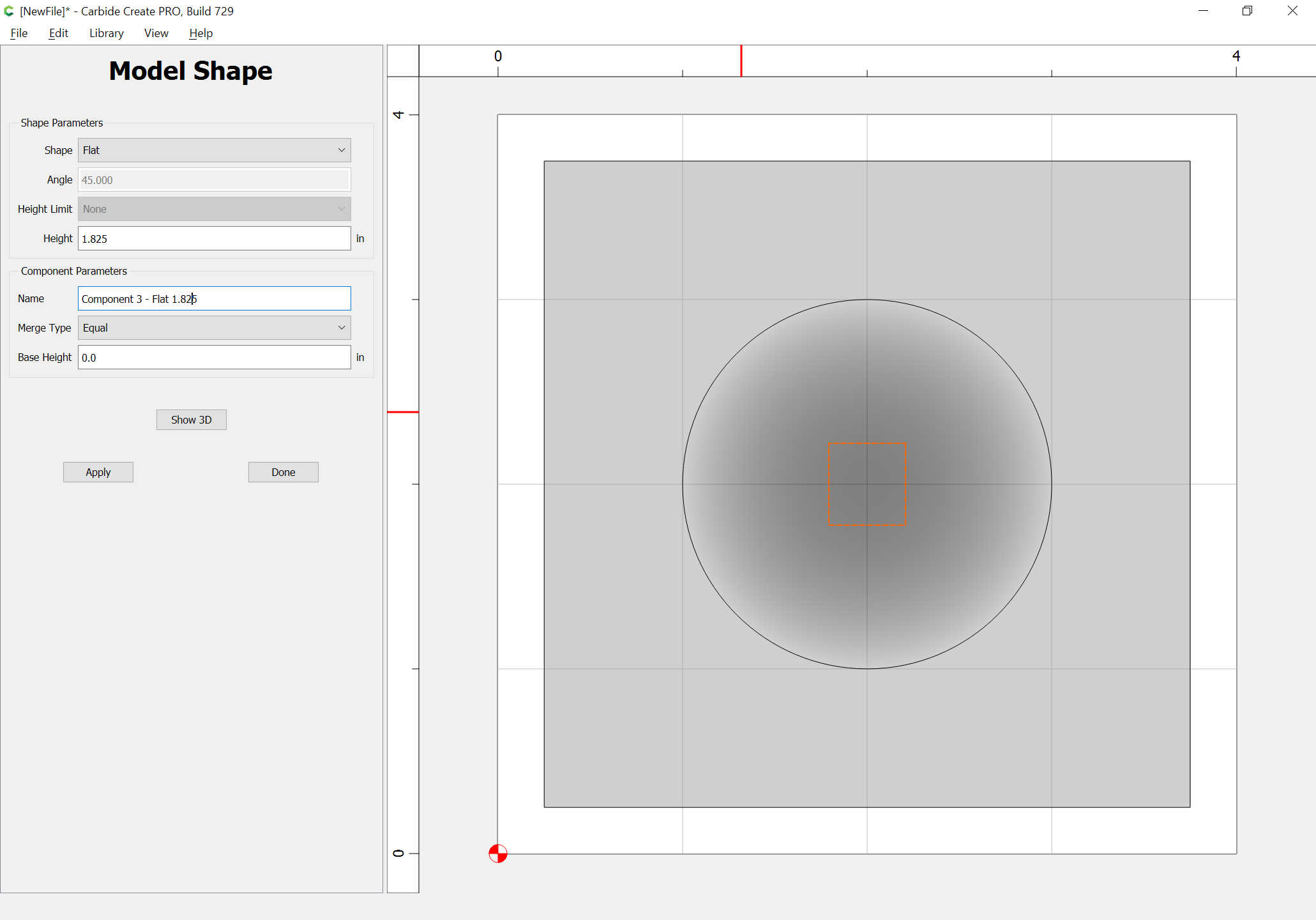
Let’s try something a bit more basic, just to test:
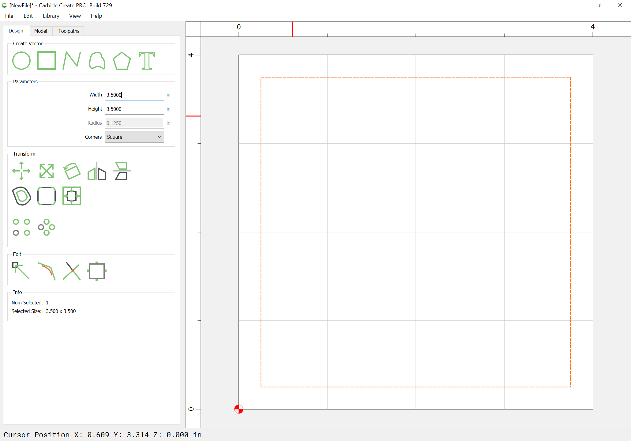
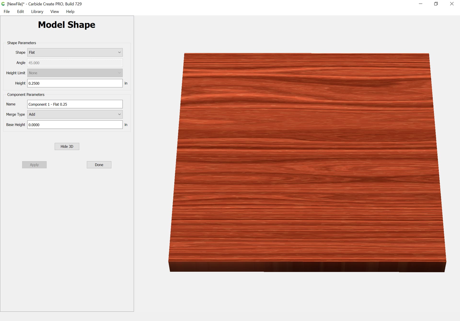
Model this as a flat object to a height of 0.25:
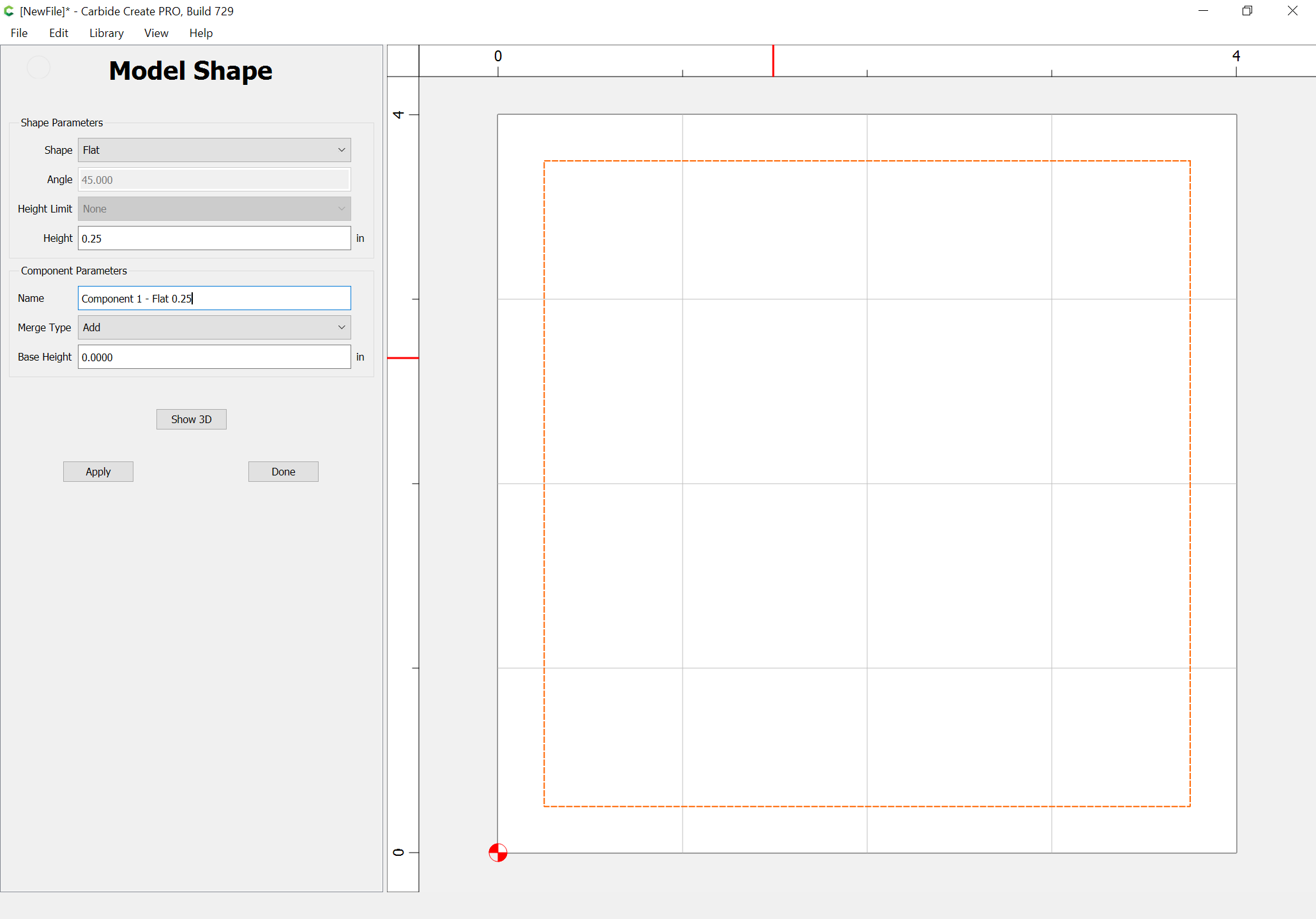
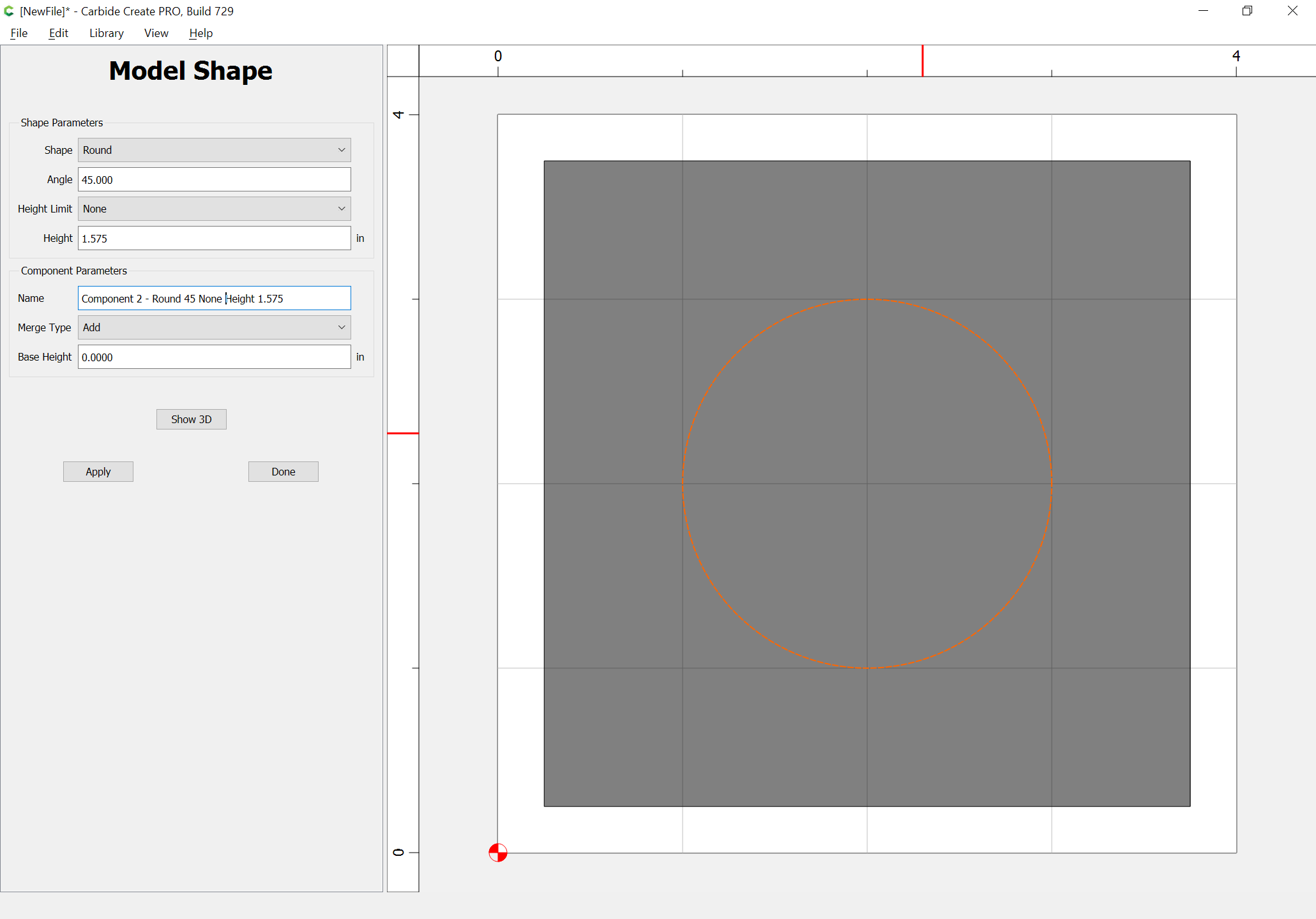
Draw in a circle — for the height of this, we have:
1.825 - 0.25 == 1.575
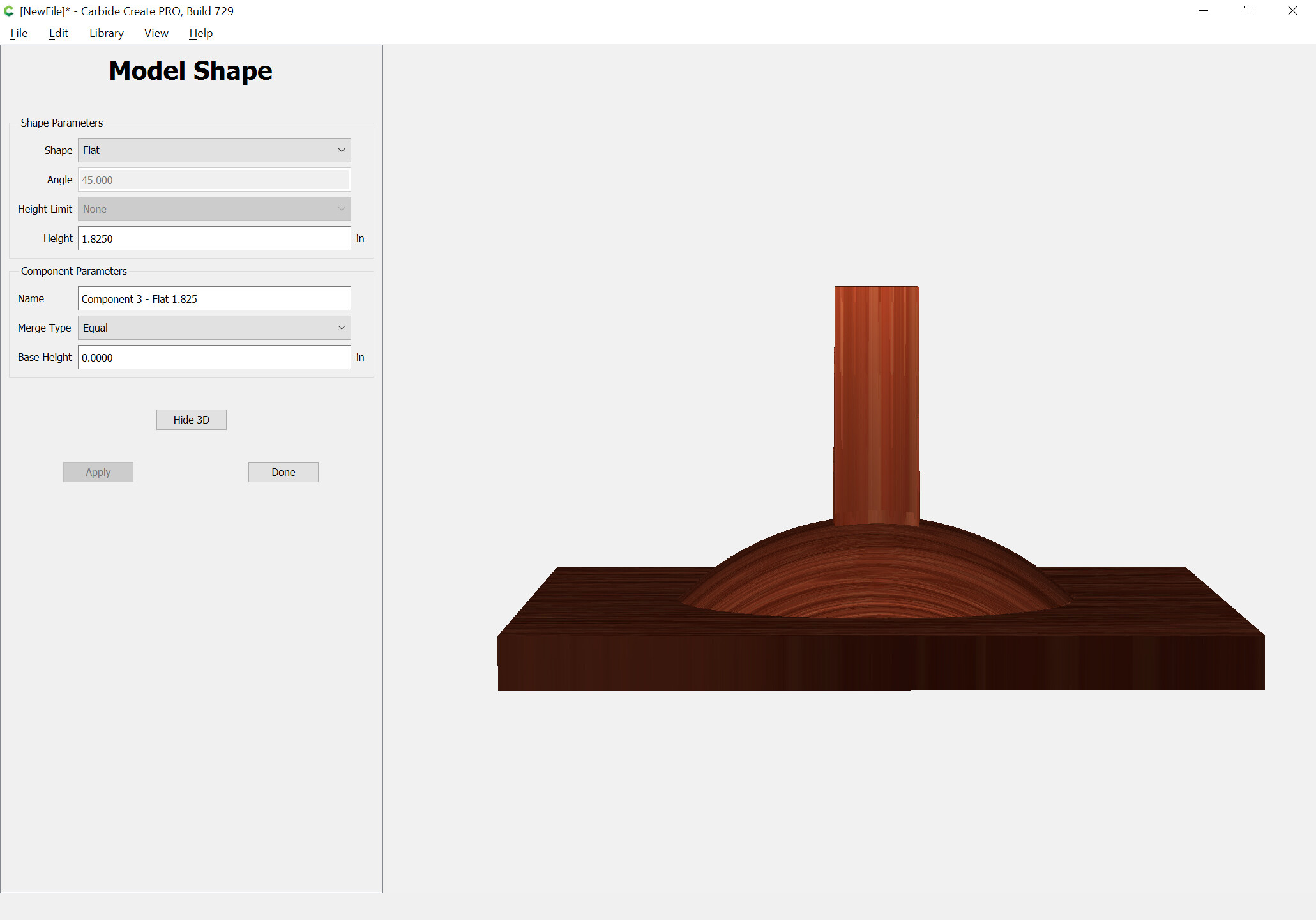
additional height to add:
Let’s add an object to check how tall it actually is:
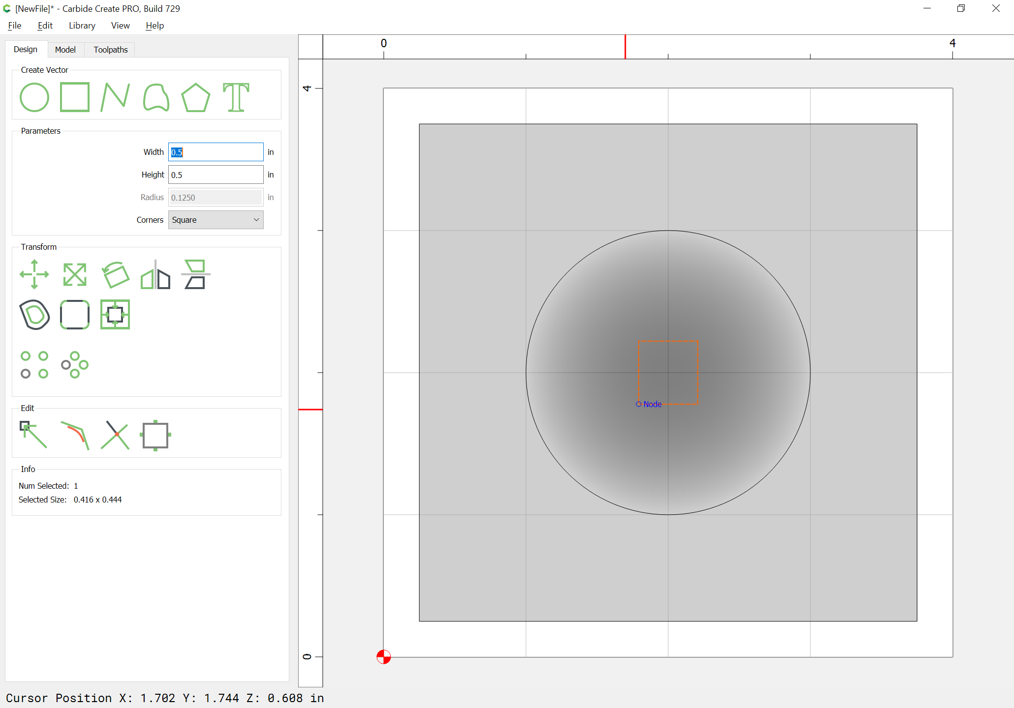
Disable this object, and try again w/ the rounded form.
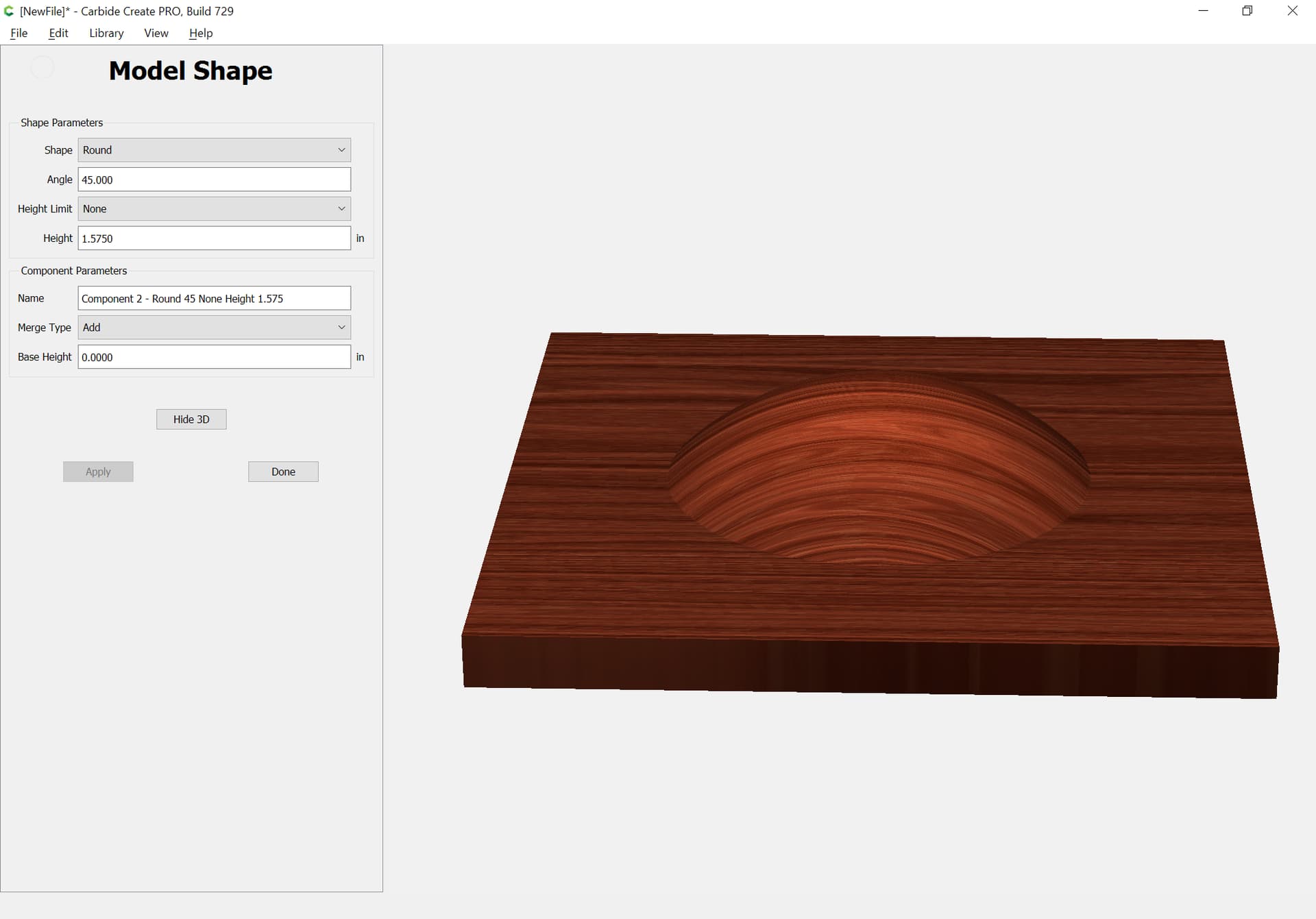
Select the circle again and model it using Scale height:
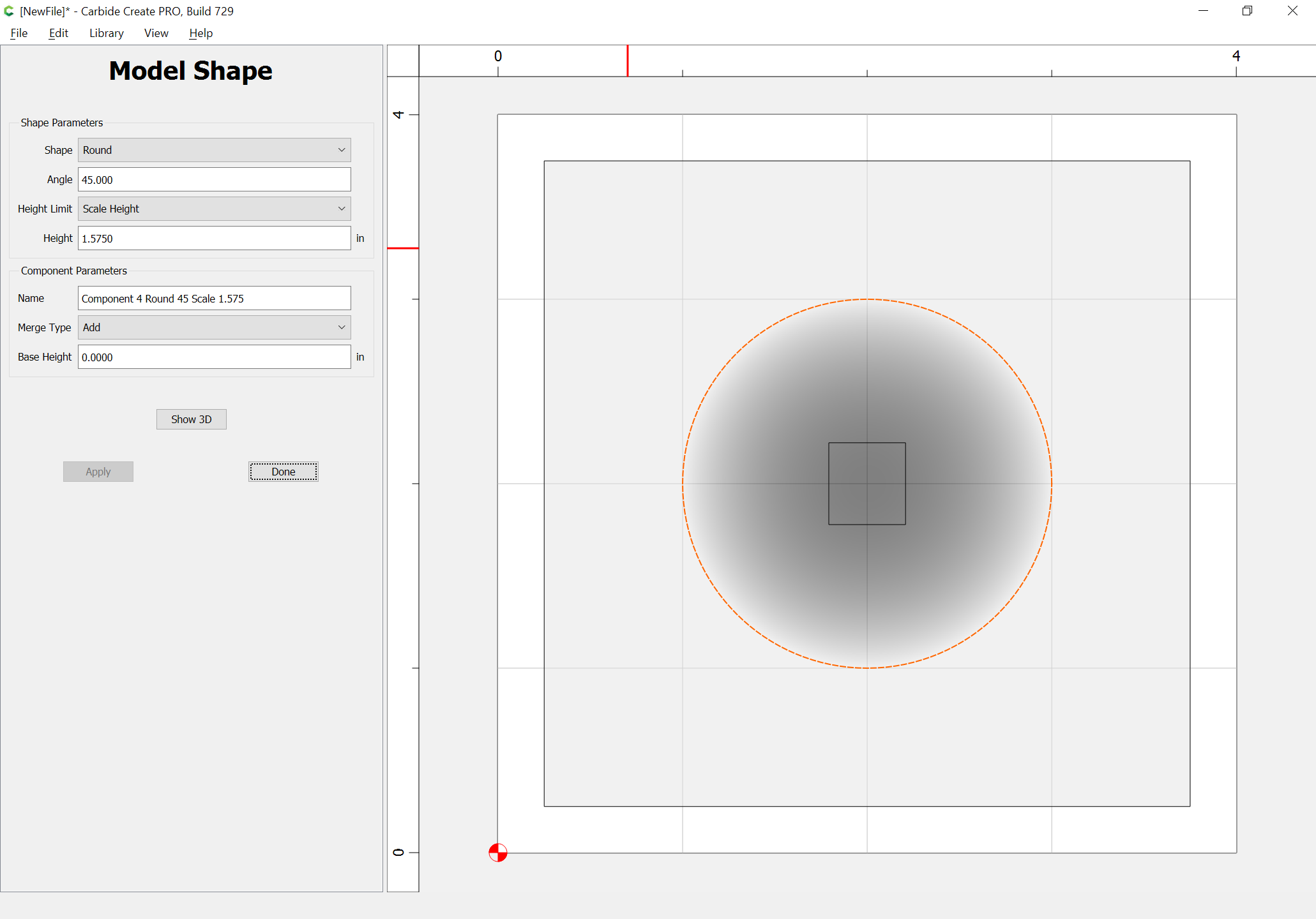
(delete the previous component, and remember to disable the measurement square)

If you haven’t already seen this, @StephenCox made a easy to understand video on modeling turtle shell. It may help to follow along with his example and apply his technique to your design