High Speed Chatter (Video)

It’s sometimes in the catalogs, not always on the websites. I suspect these guys aren’t selling much through the web.

SECO

Dormer-Pramet (not just Aluminum)

KOMET has been acquired by Ceratizit and the current products should show up on that website instead. Looks like its mostly drilling tools for now though; the WNT endmills are present however.

1 Like

Most of the MEMS chips aren’t that much more expensive. Some are however mostly meant for consumer applications and support a max ODR of 400 Hz or so. Given that they all have ΣΔ-ADCs under the hood, it’s important that they permit to change the filter settings. Default is often for a bandwidth of ODR/9, and 44 Hz is not enough for machine dynamics.

Regarding the required bandwidth, I think you would like to be able to see the tooth passing frequency (e.g. 2-flute at 24k/min = 800 Hz), so sampling at 2 kHz at the very minimum, better 4 kHz.

2 Likes

Hmm, I was looking at the catalogue for my Sumitomo supplier and it turns out they sell endmills from Hartner, which specifies its rake and helix angles (as well as the standard geometry of course) and they’re fairly affordable (6mm 3-flute endmill is 20 CHF) and happily sell to individuals.

I’ll have to try them out.

Hmm, I suppose it’s out of the question to take measurements from multiple cheap sensors so that they’re out of phase with each other?

e.g. if I have 2 sensors that sample at 2kHz, I can sample both at 2kHz, offset by 25µs and treat them as a single 4kHz sensor?

I’m probably overcomplicating things for no reason, aren’t I?

There are quite a few gotchas when you try to ‘oversample’ the sensors.

Latency becomes an issue, you don’t know the actual ‘age’ of a measurement from the sensor accurately enough and this induces noise in the time axis, turning your data to junk pretty quickly. This is a type of noise that is generally very pooly understood and there are few ‘off the shelf’ algorithms to deal with it.

Many sensors have some sort of noise suppression, low pass filters in the analog amplifiers etc. which you run into when you try to oversample, you’ll not reconstruct anything above the nyquist frequency this way, just get more readings limited below it.

The noise inherent in alternating readings between sensors becomes a significant issue and it’s a hard one to deal with in post-processing, it can be done but it can result in a loss of bandwidth.

I’ve generally found that putting the money in the signal acquisition device is more effective than post processing, unless you are prototyping to make a large number where unit cost is an issue and you have purchased much better reference sensors to optimise your design and signal processing pipeline against.

Oh, that sounds complicated. I don’t think the better/higher ODR sensors are cost prohibitive, as long as you stick with mass-produced MEMS. The ICM-20649 is 5€, the ICM-42605 supports 8 kHz ODR and is €2.60. This one is only 16g but a later model; I’ve tried the 8 kHz and it’s possible, but a little difficult for an MCU to keep up with more than 3 of them.

The integration, i.e. getting them tiny LGAs on a PCB that works well mechanically and can be attached properly is a bit more difficult than buying the sensors… That’s why I think the Adafruit (or other) break-out boards are a worthwhile shortcut for a quick solution.

Thanks for the Hartner find! Some of those look promising indeed.

1 Like

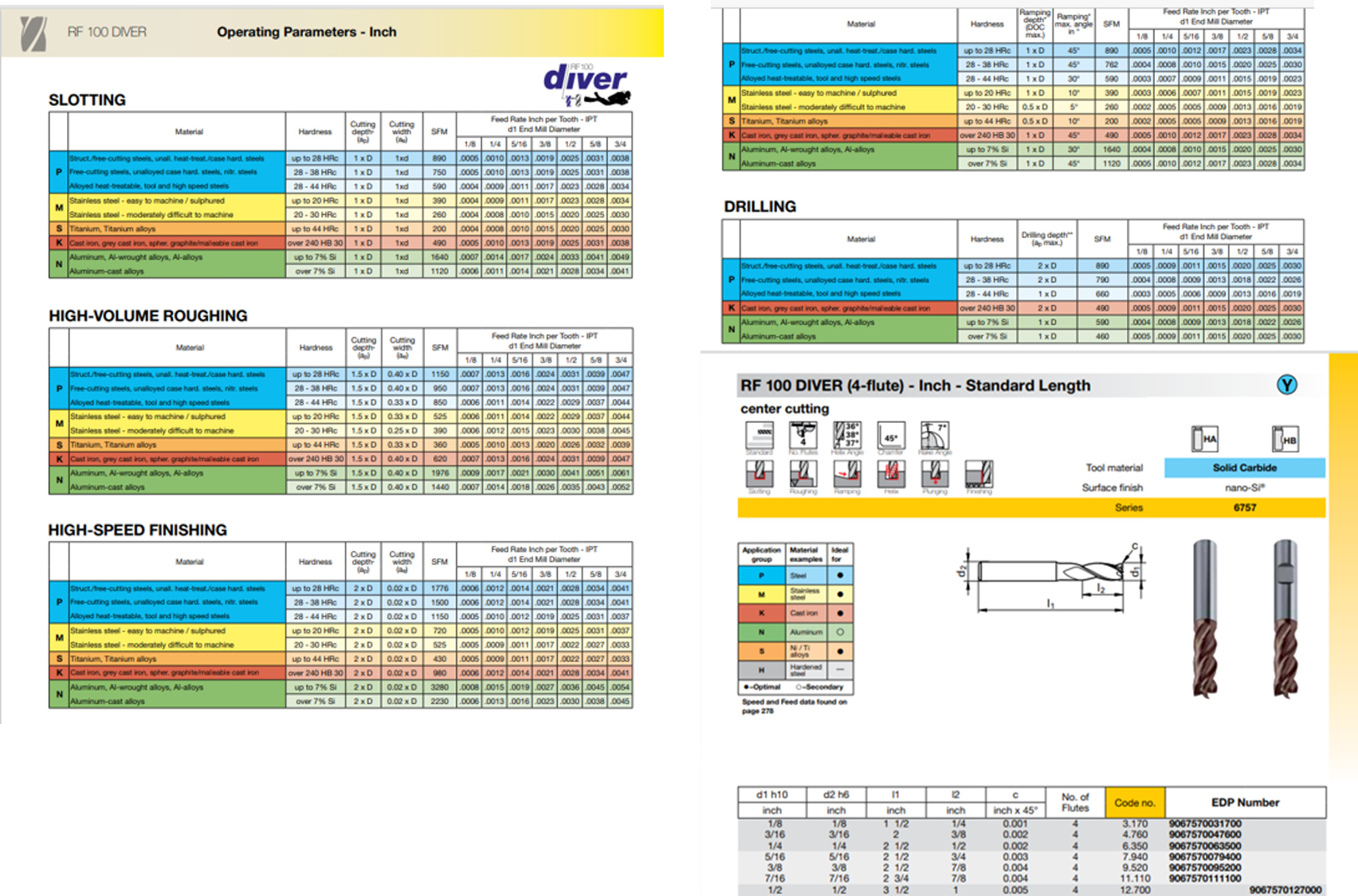
Some Guhring endmills offer high speeds and have detailed operating parameters and radial rake angles. Would axial rake likely be the same?

Good find! Nice that they have all that data.

This particular one doesn’t look like a terribly good fit for our machines though. Unless you’re thinking about cutting steel, of course.

It’s four-flute, coated, and since they suggest it for ISO-M and S, very likely has a rounded edge (edge radius 15 µm or more), and the rake angle is not large. I would assume the axial rake angle is small as well, maybe 0 - 6°, because otherwise it won’t survive plunge-milling M and S very long.

Austenitic stainless (M) is a bad heat conductor, as is Ti (S). That means the shear zone gets very hot, and to protect the tool edge from heating up too much (and thus loosing strength itself) a rather thick coating is applied, where the coating material is selected for hardness and heat resistance, not low friction. That invariably increases the cutting edge radius and generates higher cutting forces in materials where you wouldn’t need that type of coating, like aluminium.

1 Like

Some folks like @Vince.Fab and @RichCournoyer do cut steels and even Titanium on Shapeokos, Nomads, and other “hobbyist” machines. High cutting speeds and low feed rates help enable that, right?

Like @spargeltarzan pointed out, in those materials, heat management is a big deal.

Usually its a good idea to factor in sfm first, then figure out the balancing act between rigidity, spindle power, and actually cutting a big enough chip to manage the heat.

Had a little high speed chatter on a stock S3 with 0.375 KOR 5 flute in aluminum yesturday :sweat_smile:

Nja, depends. Many steels work-harden, especially austenitic stainless (e.g. AISI 304, 316 etc). Every cut involves large plastic shear deformation in a thin zone near the surface, and as a result, the freshly cut surface can be harder than the original material. Now, if you take a big-enough chip, the next cutting edge is biting into the material below the hardened zone, but with a very small feed/chip thickness, you will plough precisely through that thin sliver of the surface that the previous cut just hardened. Not optimal.

Increasing cutting speed will increase temperature in the shear zone. In one way, that is beneficial because the strength of the material usually drops with temperature. But: The hardness of the tool drops with temperature as well - edges will blunt quickly (effect: rake down, edge radius up), tool life goes down more than productivity increases. This is much less pronounced in aluminium alloys, because they loose much of their strength at 300°C which isn’t very challenging for Carbide. In alloyed steel, you can easily reach 700°C at high cutting speeds. You may get away with that with very good heat management (high-pressure internal coolant, very small AE or AP), but without, the tool will be blunt after a few inches and start to throw white sparks (meaning > 1000°C).

Most of us have experienced this exact problem: Run a HSS drill at too high RPM in steel, and it will blunt before you make more than a little dent. Happens quickly because the heat can’t get away in this case, and the blunt tool only makes things worse (higher forces, more friction, more heat…)

6 Likes

Wouldn’t/shouldn’t those factors be accounted for in the manufacturer’s speeds and feeds recommendations? Apparently it’s important to stick with their speeds (SFM) and feeds (IPT) as closely as possible? Do those endmills offer higher cutting speeds (SFMs) than most for those harder materials?

They are, but only approximately. The tables are only half a page and do not distinguish more than a handful of broad material categories. As an example, 1.4301 (or AISI 304) is the a widely used stainless steel. Annealed, it’s yield strength is about 190 MPa (28 ksi, yes - that’s less than 6061) and UTS around 600 MPa (87 ksi). Heavily cold worked, such as in small-diameter rods or sheet material, than can easily go up to 1400 MPa (200 ksi):

Clearly, the two conditions require vastly different machining parameters, but AISI 304 just falls into one row in the table of recommendations.

In short - no, the table of recommendation doesn’t account for everything. And it’s important to remember that the operators of Mazaks, Chirons, DMGs or Ingersolls who are buying most of the tools aren’t really all that concerned with cutting forces as we necessarily are.

1 Like

Should the tools be safe using the manufacturer’s recommendations on those machines with the harder materials? How about on force limited machines like Shapekos, Nomads, and other hobbyist machines (ignoring the impact of force on the machine)?

What does safe mean in this context?

Not break or cause endmill breakage.

No, the machines will most likely not be damaged, but a DC < 10 mm or long-flute endmill will certainly break if the material shear stress is far higher than what the recommendation was written for. Since strength goes up with D^3, the larger diameter endmills may give you enough time to recognise the problem.

1 Like

So, you get to say “that doesn’t sound good” and reach for the button before the cutting faces are cooked :wink:

I’ve read through this thread and others, and seen Millalyzer mentioned here and there. It seems like a useful tool, but the only results when googling it are on this forum. Is this program available to the public anywhere?

here: https://millalyzer.lophostrix.com/

5 Likes

I think it’s a useful program and well worth the very reasonable price.

1 Like