Yes. This was recently discussed here, and I worked up a solution … here, from a PM:
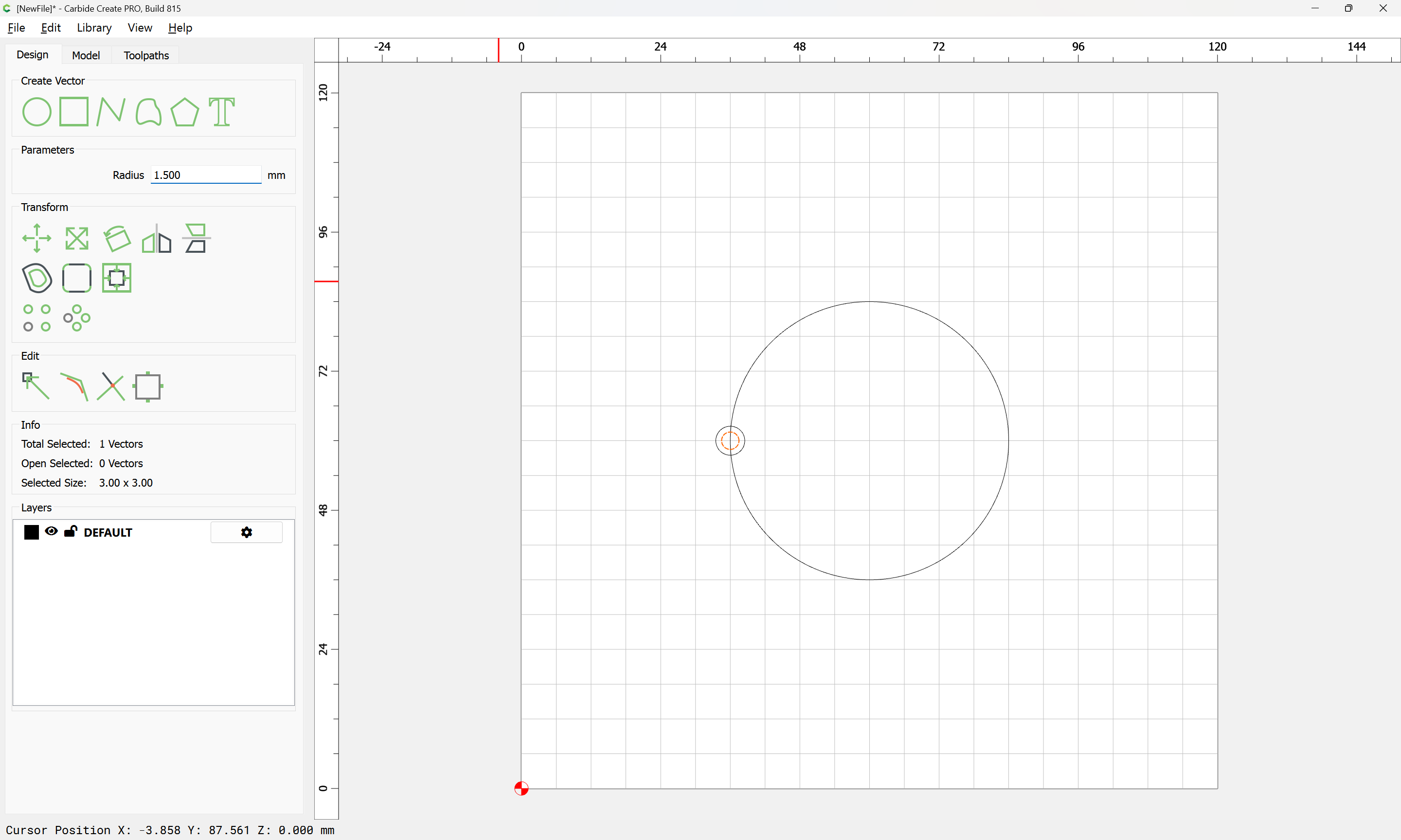
Draw a circle of the desired diameter:

Draw a circle of the diameter which the threadmill will cut:

and which shows the diameter of the shaft:
Duplicate and reduce the diameter of the original circle by the shaft diameter, plus a bit of clearance (assuming one wants to cut the groove as deeply as possible)


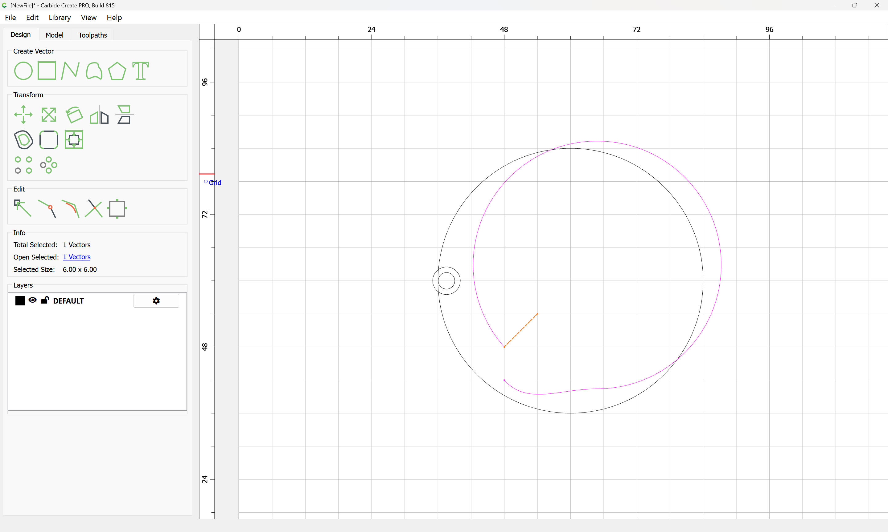
Reposition the tool proxy to get an idea of what the cut/clearance will be like:
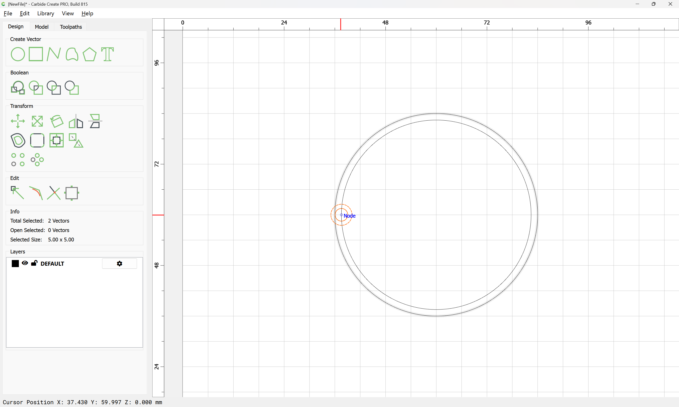
Select the inner circle which will be used for the toolpath:

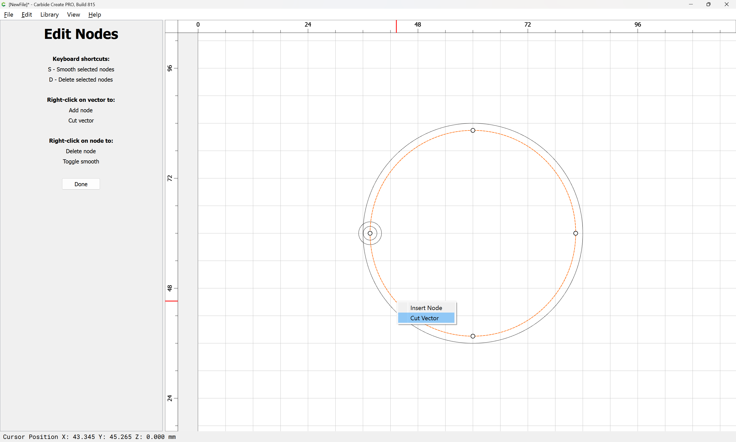
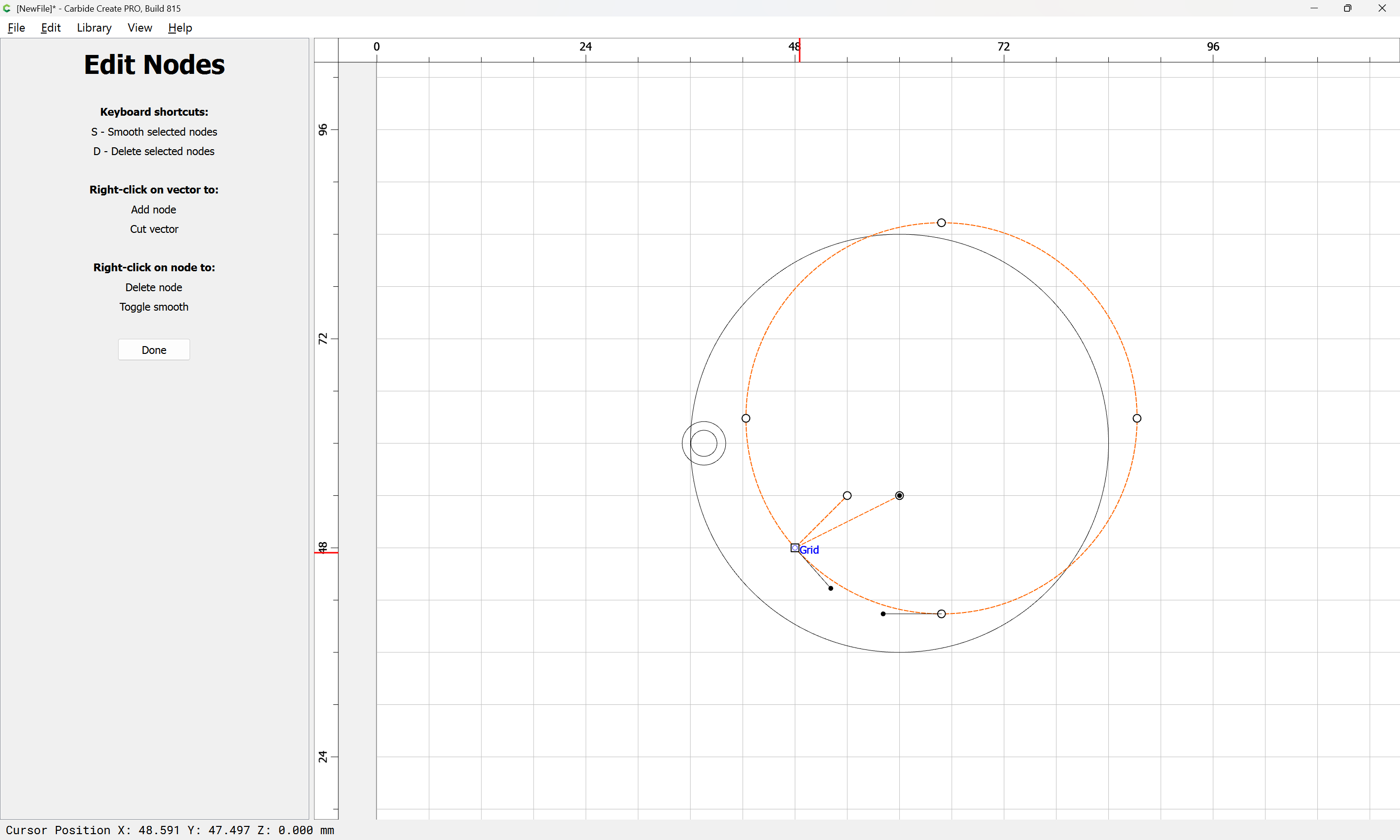
and go into Node Editing mode:
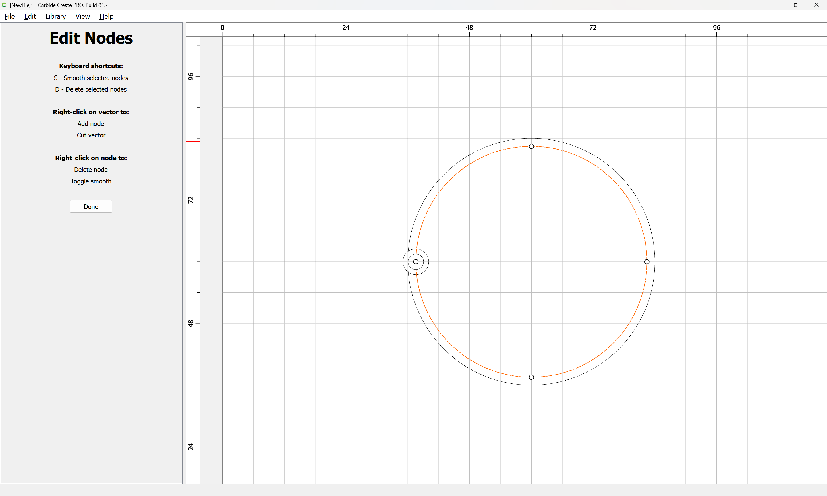
and right-click where you want the path to begin/end cutting:
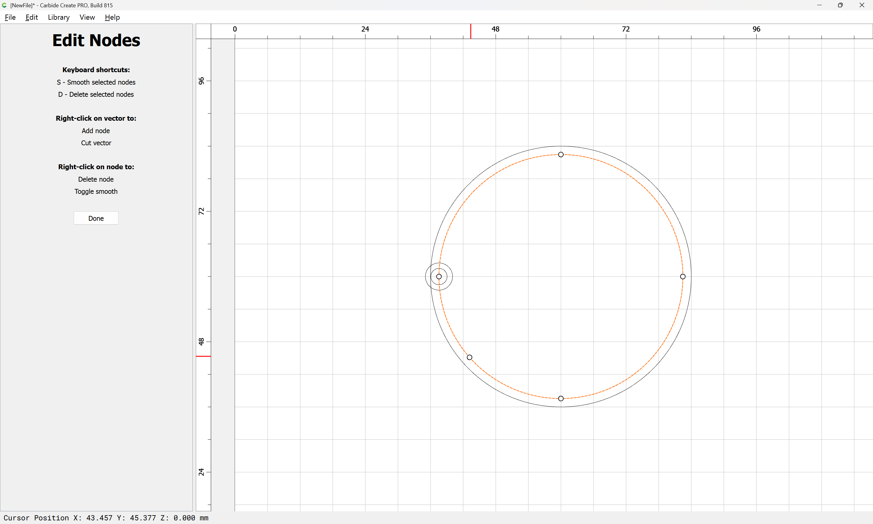
Done

Drag that new node to a grid intersection:


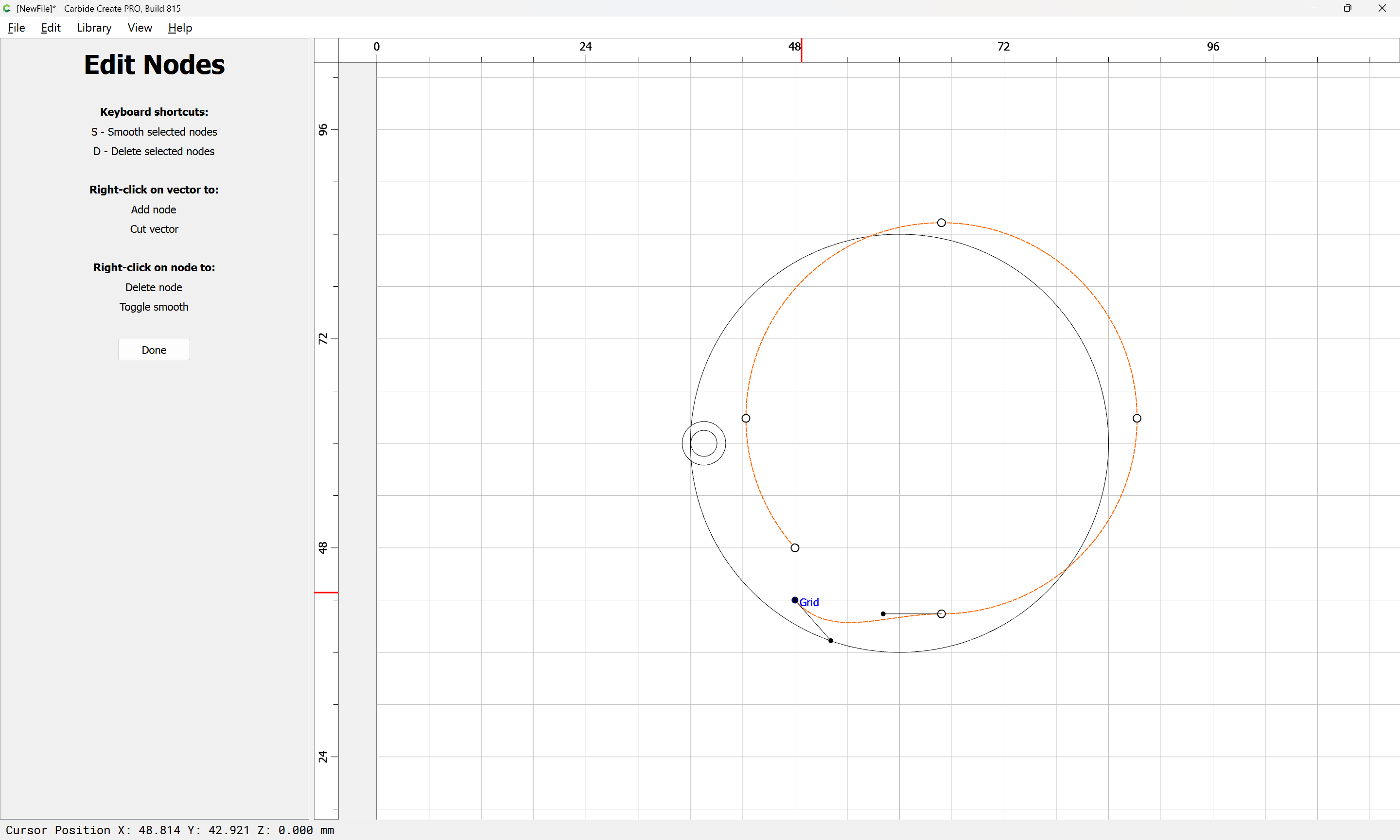
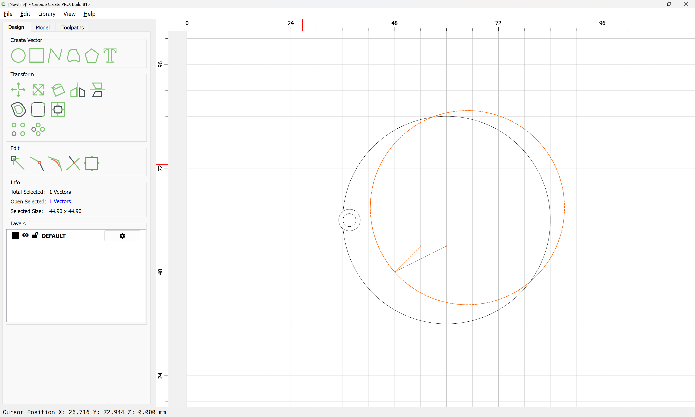
go into Node Edit mode again:

and drag one of the nodes to a different grid point:
Done

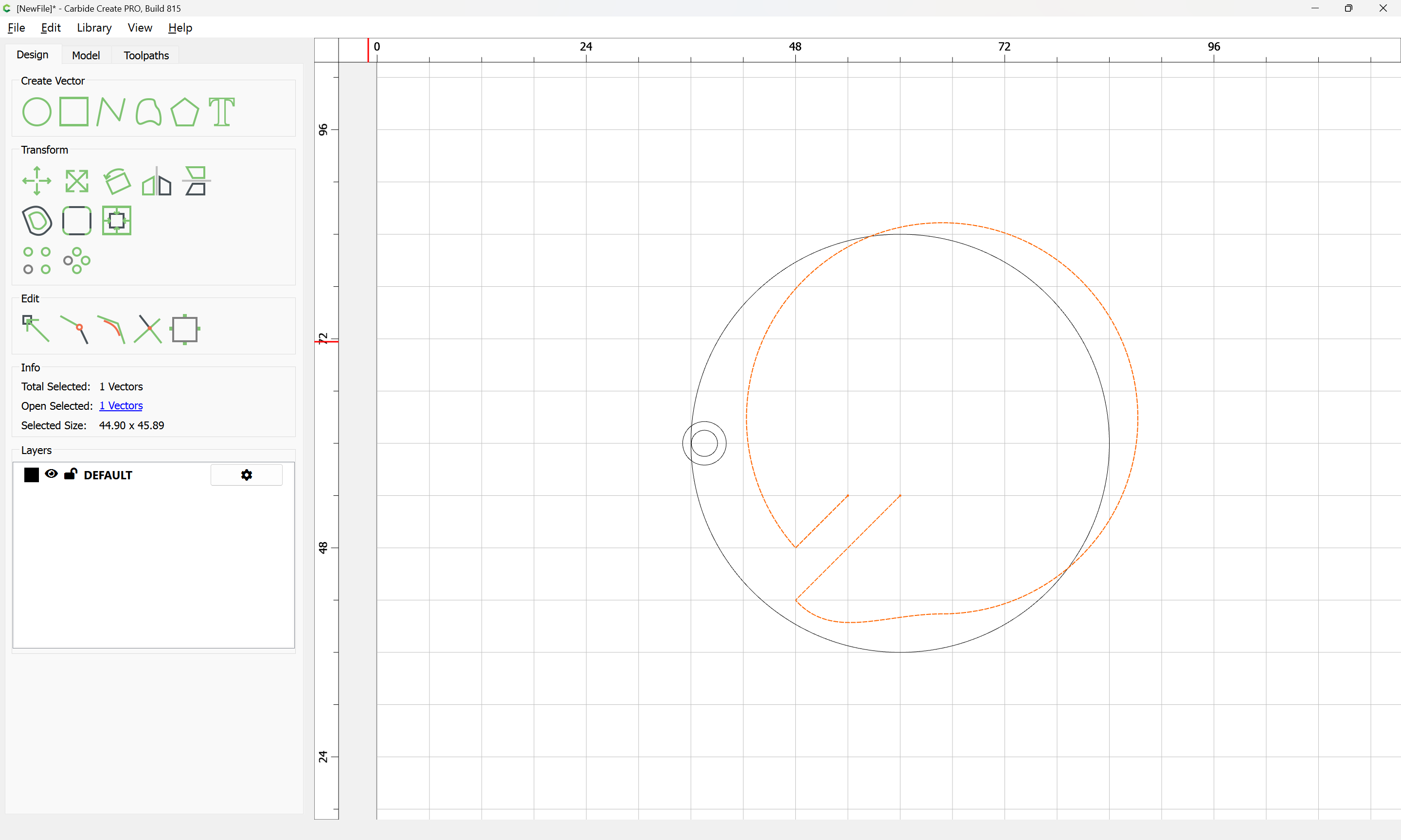
Draw in two lines which are longer in length than the cutting radius of the tool:
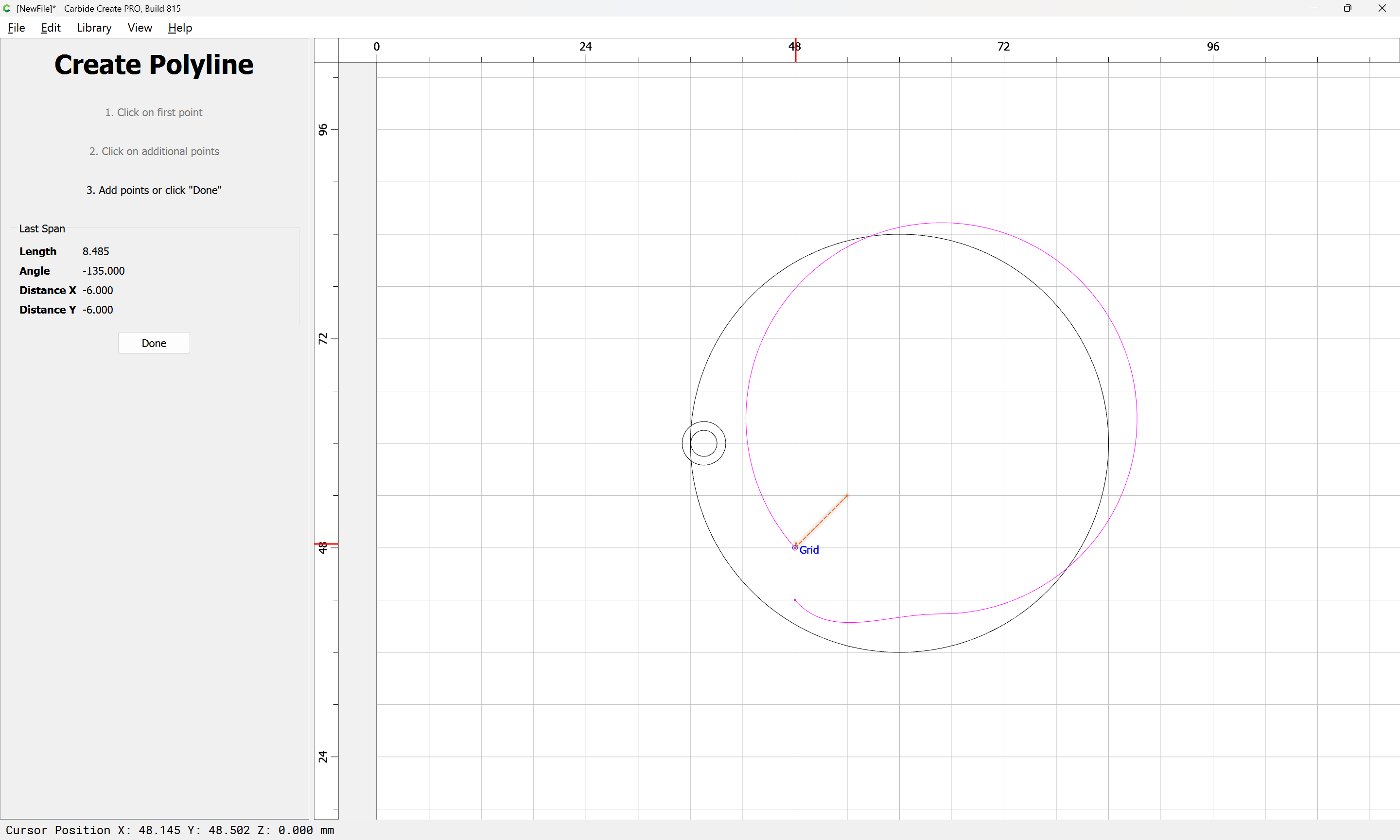
Done
each of which connects to a begin/end point:

Done

Select the open geometry:
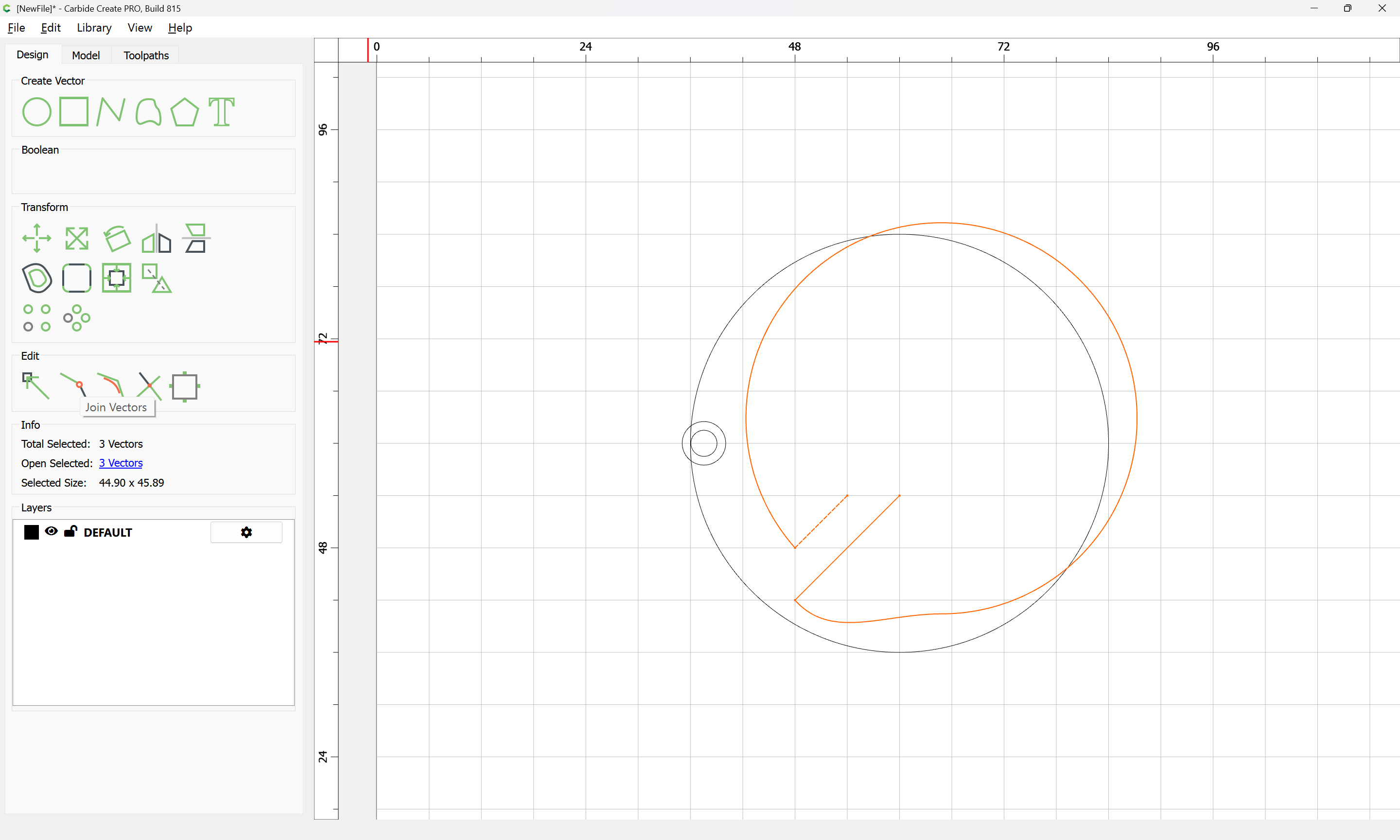
and use Join Vectors to connect things:

Yes
Go back in to Node Edit mode:
d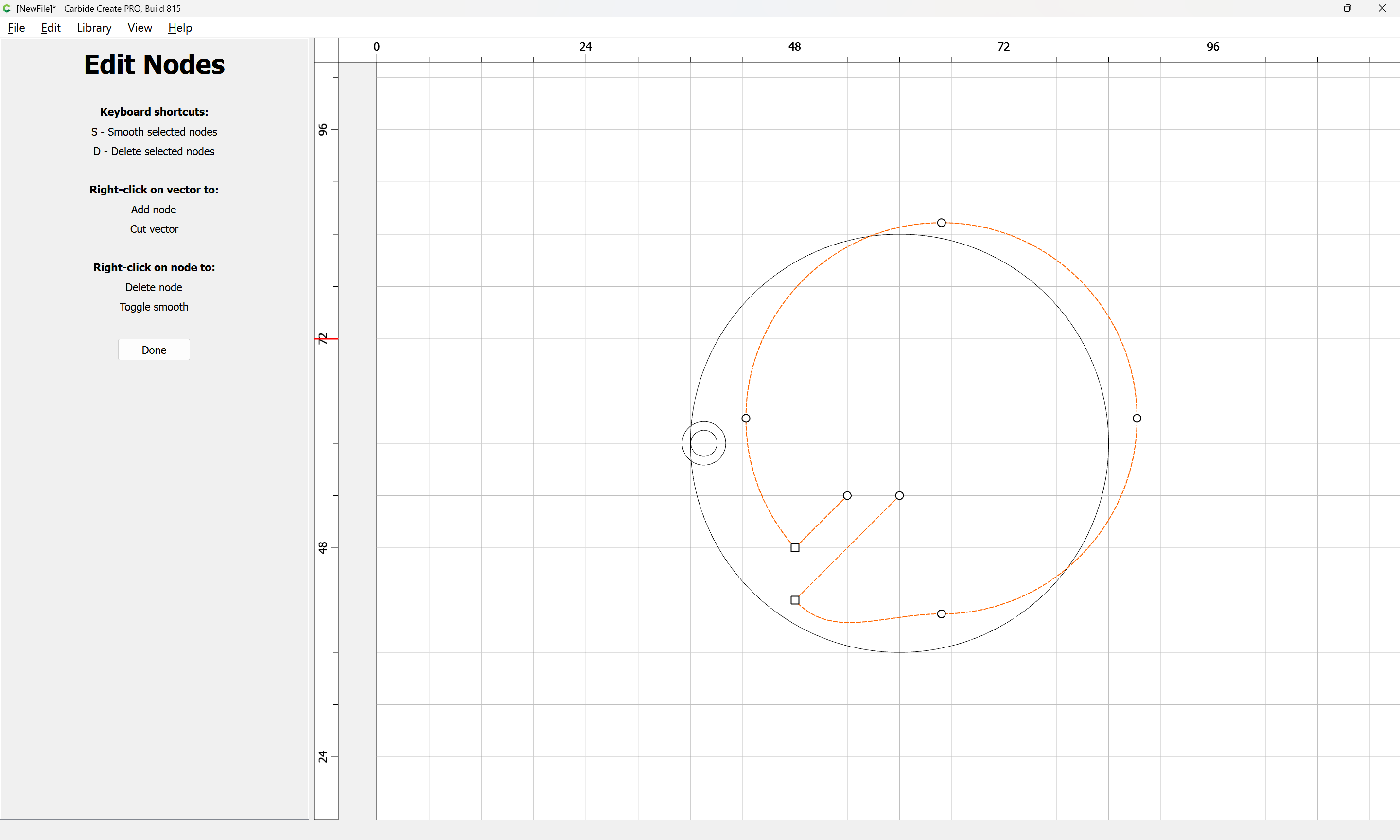
and drag the re-positioned node back into position:
Done
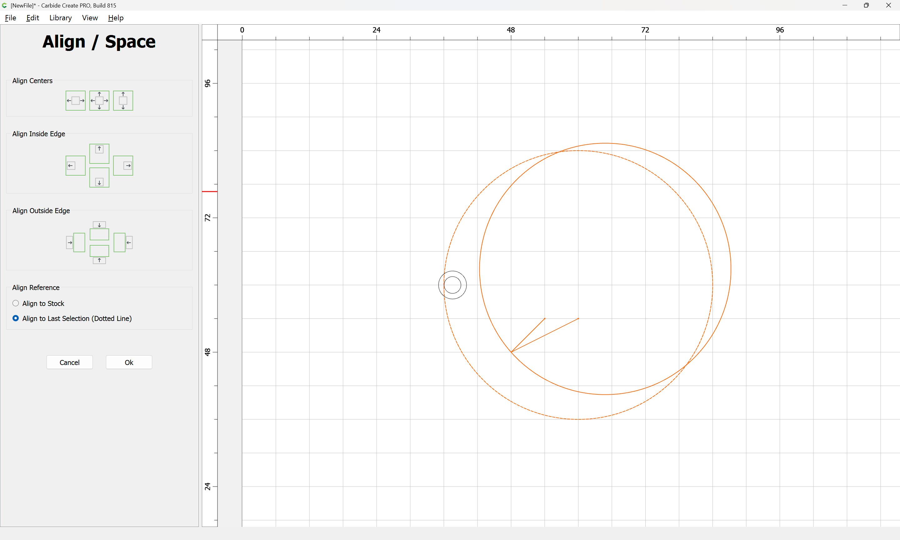
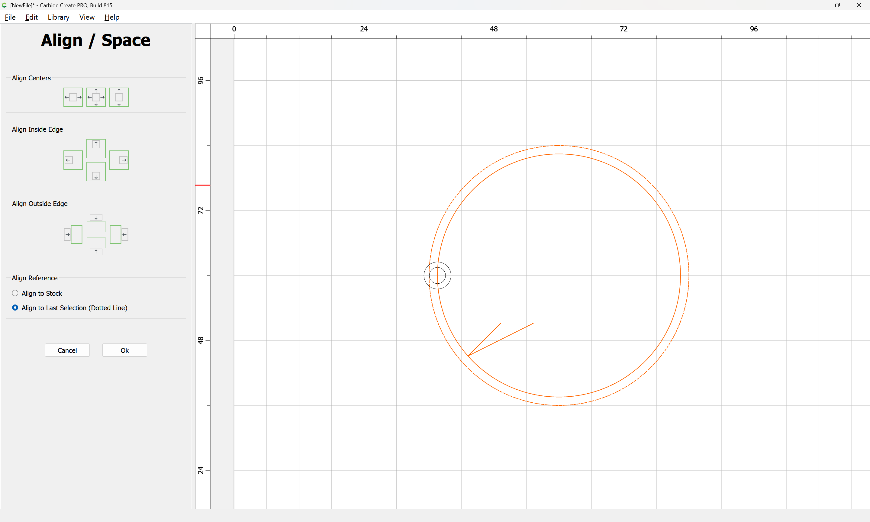
Re-align the edited geometry with the original

Align Vectors
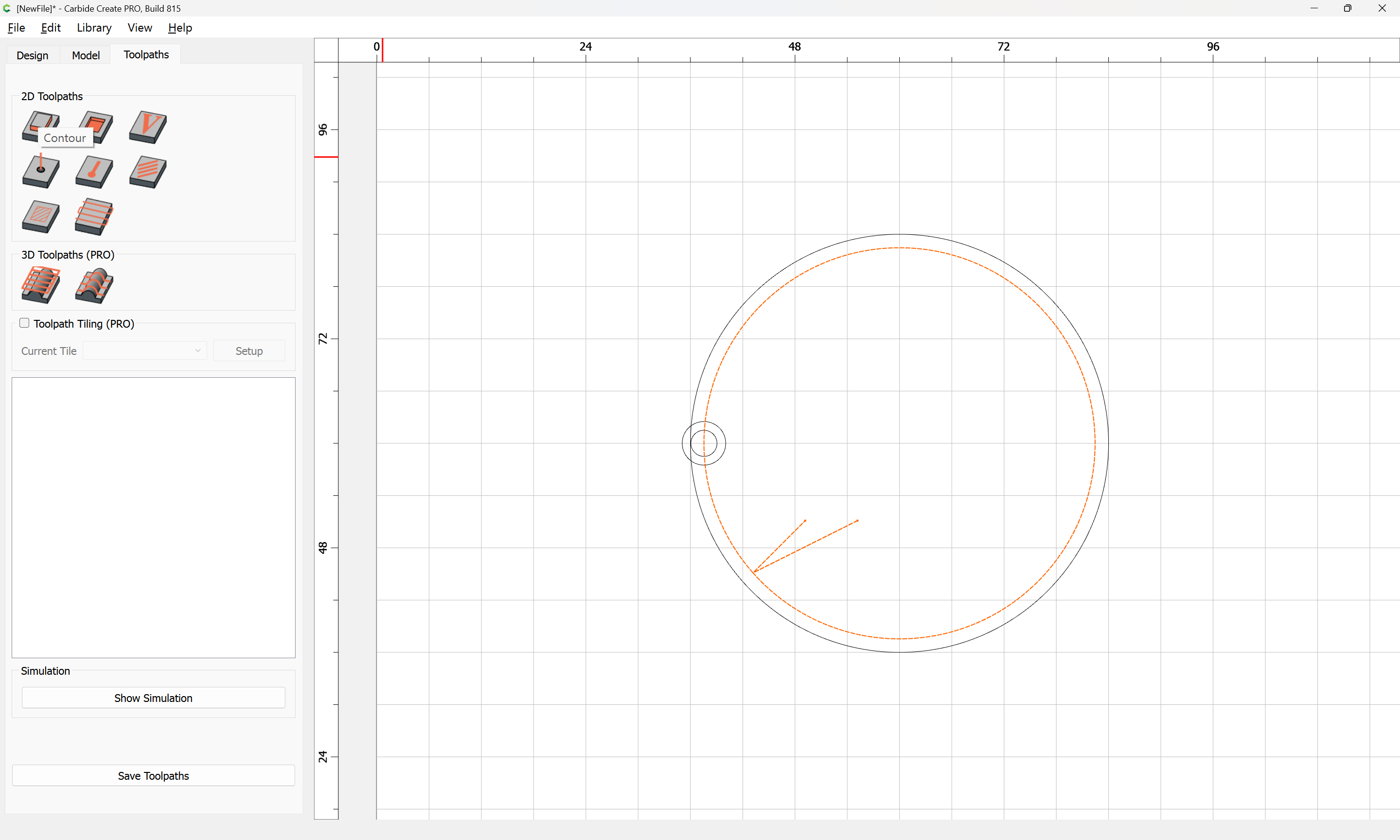
Assign a No Offset Contour toolpath:
setting the Depth per Pass:
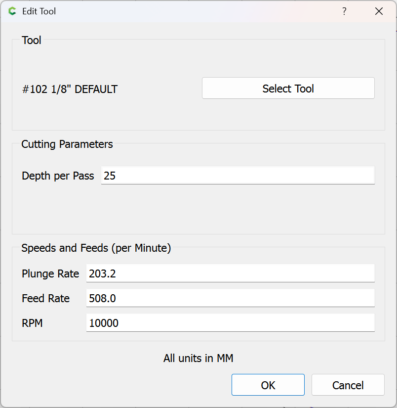
to be greater than the Max Depth:

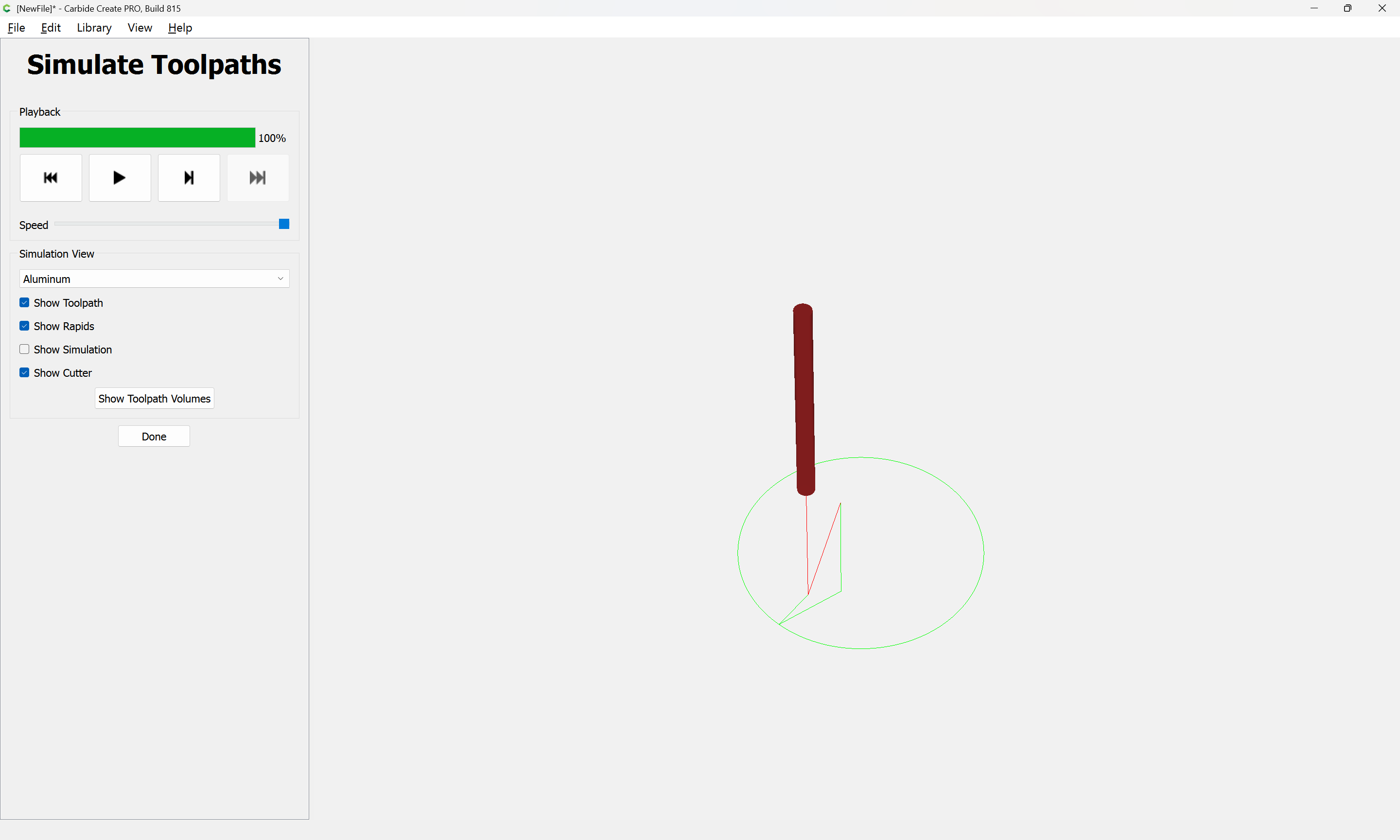
and when you preview the cut you should see that it will plunge to that depth, move in to the cut sideways, follow the geometry to the end, then lift after exiting the cut.