I made a coaster and I followed the instructions more or less on how to get it cut via the very helpful tutorial on the shapeoko website…
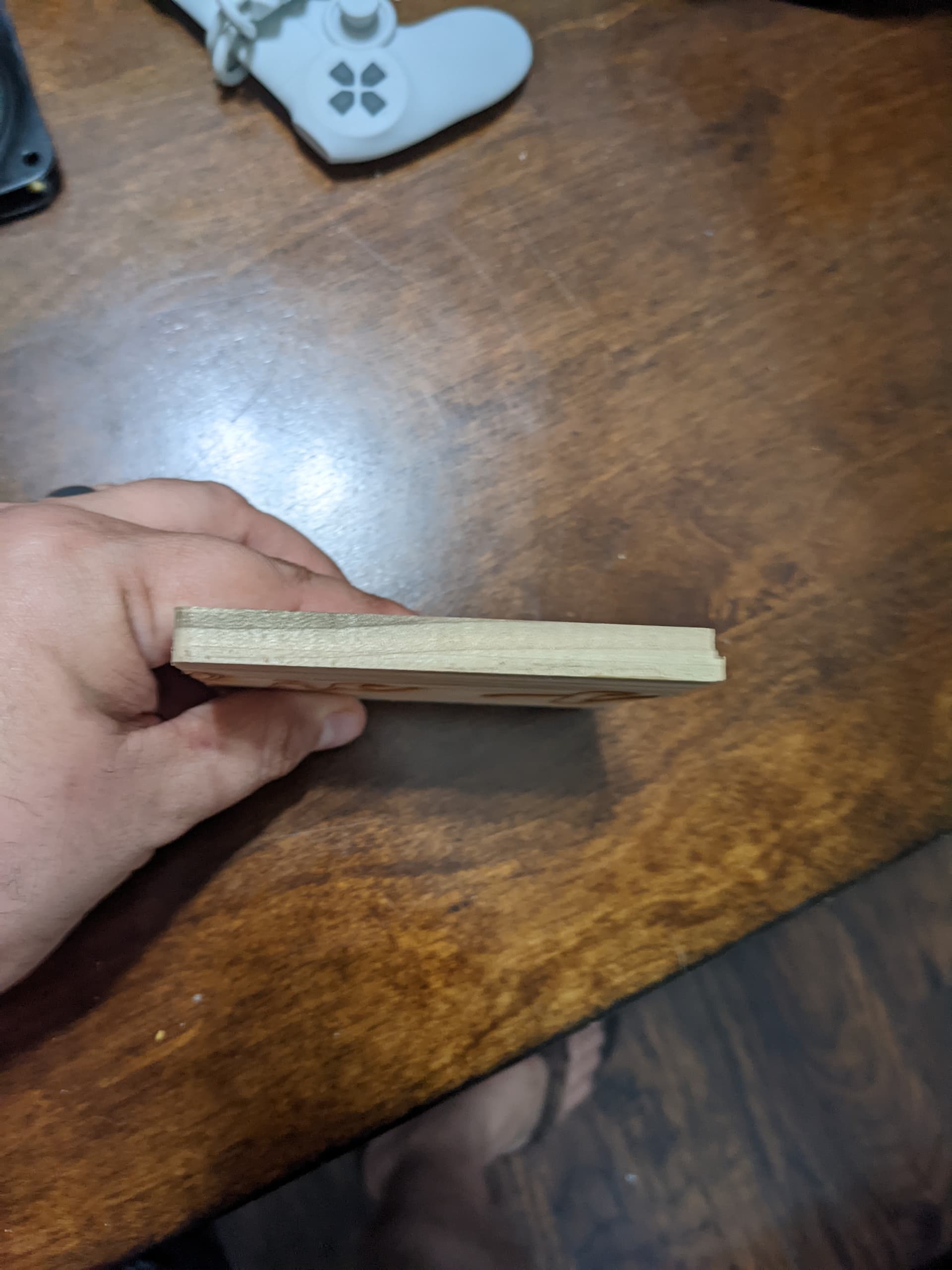
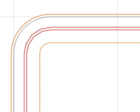
I was a little disappointed on some of the lines not adding up. Two of the sides ended up being longer than the other two halfway into the cut. Have you guys ever seen this before?
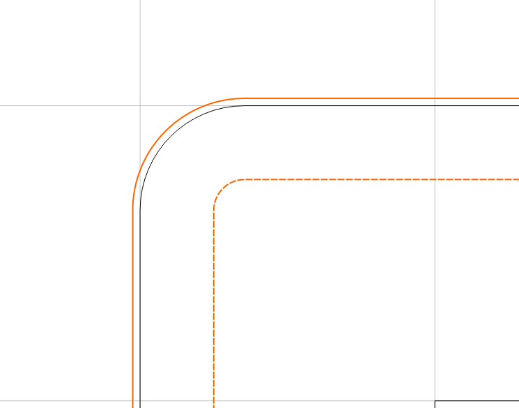
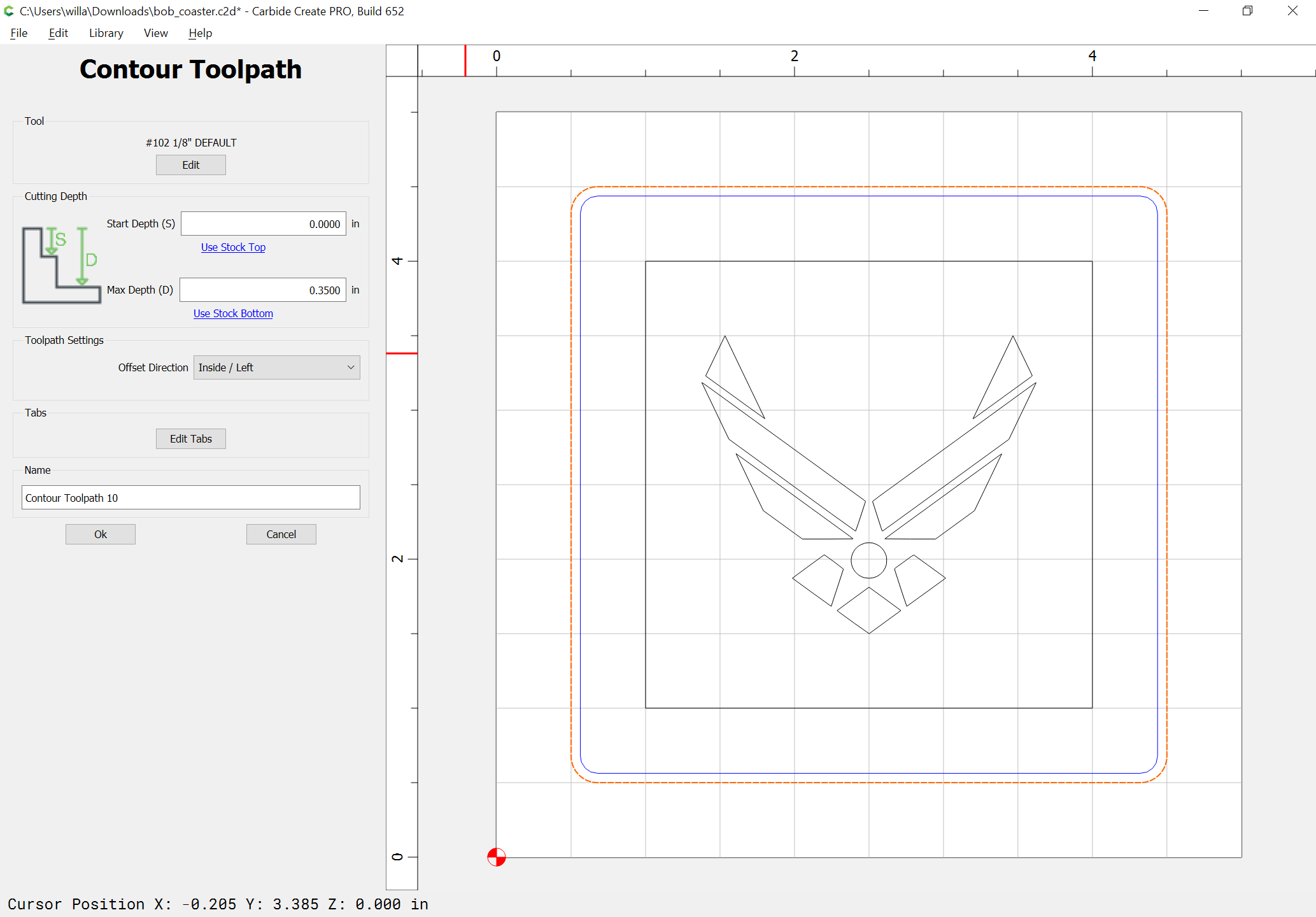
Which dimension is off? are the first cuts too small or the deeper cuts too large? You are cutting a slot with a small endmill, this should be avoided. If you take your present outline and add an offset 0.125" inside, then select the new vector and apply an outside offset that is tool Diameter +10% (0.1375") and make a pocket between them it will reduce the cutting forces on the endmill and reduce the likelihood of issues due to high cutter engagement. You’ll also want to verify your machines mechanical set up; V wheels, Belts, belt tension, pulley set screws, etc.
How does this compare to the 3D preview in your file?
Usually if the actual cut doesn’t match the 3D preview the issue is a mechanical one. Per the machine operating checklist: Machine Operating Checklist - Carbide 3D , the basic points of adjustment for a machine are:
Pulley set screws: Checking Pulley Set Screws - Carbide 3D — be sure to check all axes/pulleys (including Z on machines w/ belt-drive Z-axis, for an HDZ, check both coupler screws).
Belt tension (see the relevant step in your instruction manual, e.g., Step 5 Belting - Carbide 3D) Note that the X-axis motor is held in place on standoffs and if those bolts are loose this can cause belt tension issues. Also, belt tension for the Y-axis stepper motors needs to be even/equivalent on each side — a significant difference can cause skipping on one side eventually resulting in lost steps on both. Measuring belt tension, squaring and calibration
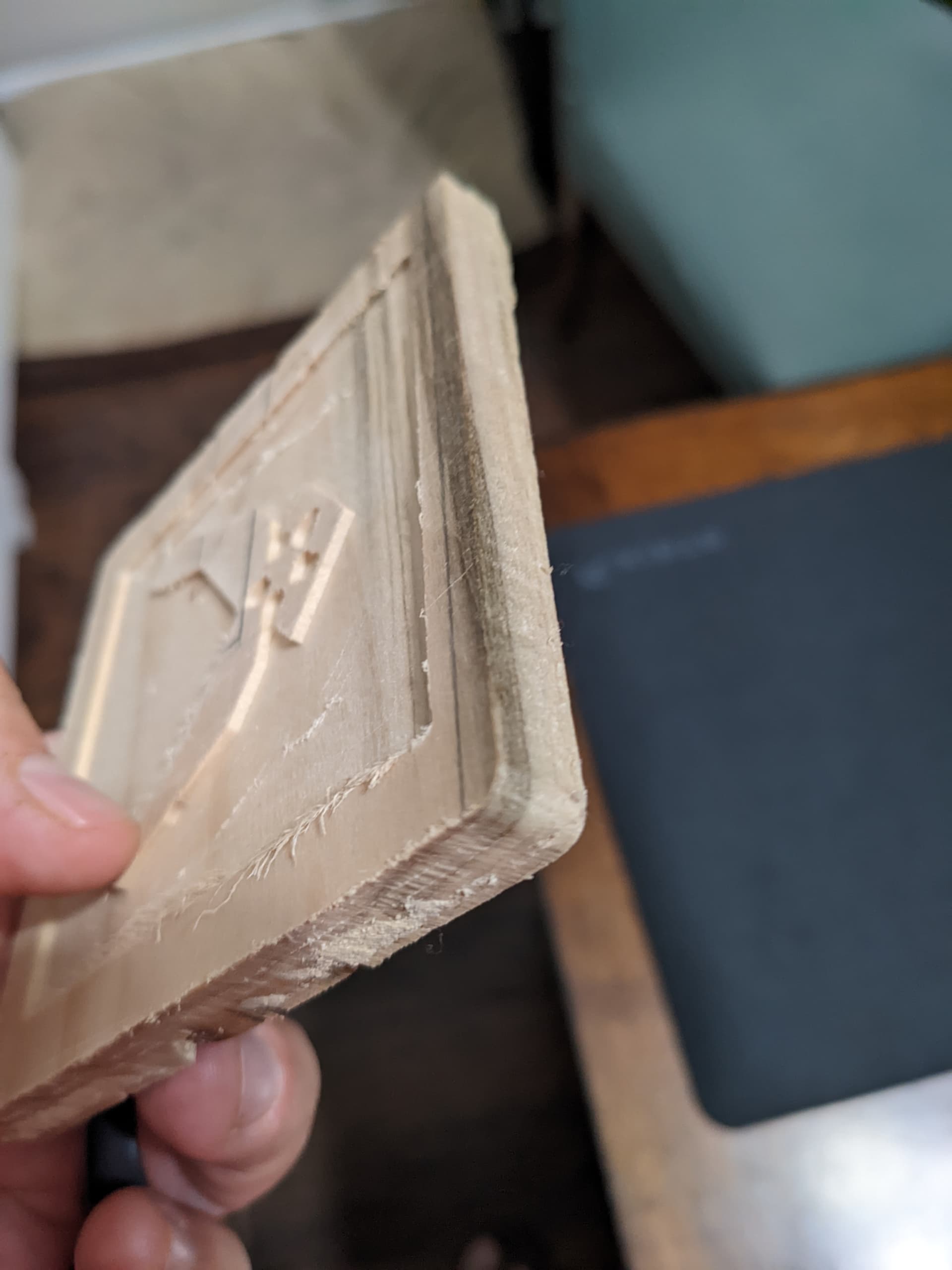
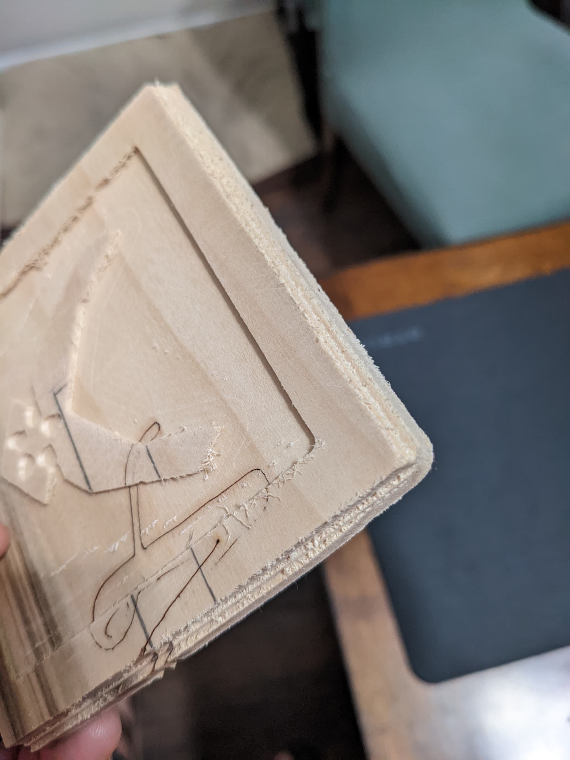
There also seems to be some wobble in the bit. It has a hard time getting past some lateral forces. it seems to struggle against the wood and then eventually overcomes whatever force it was fighting and then moves forward
Matching the endmill to the level of required detail is the way to go. You need to make sure the strategy you use is not over loading the system. Adding the extra geometry to prevent the endmill from having full engagement and make the job easier on the equipment is a good strategy regardless of tool size. This is where having the bit setter is helpful, allowing you to switch endmills easily for different portions of the job. You can still do this as separate G-code files with manual re-zeroing of the Z axis.
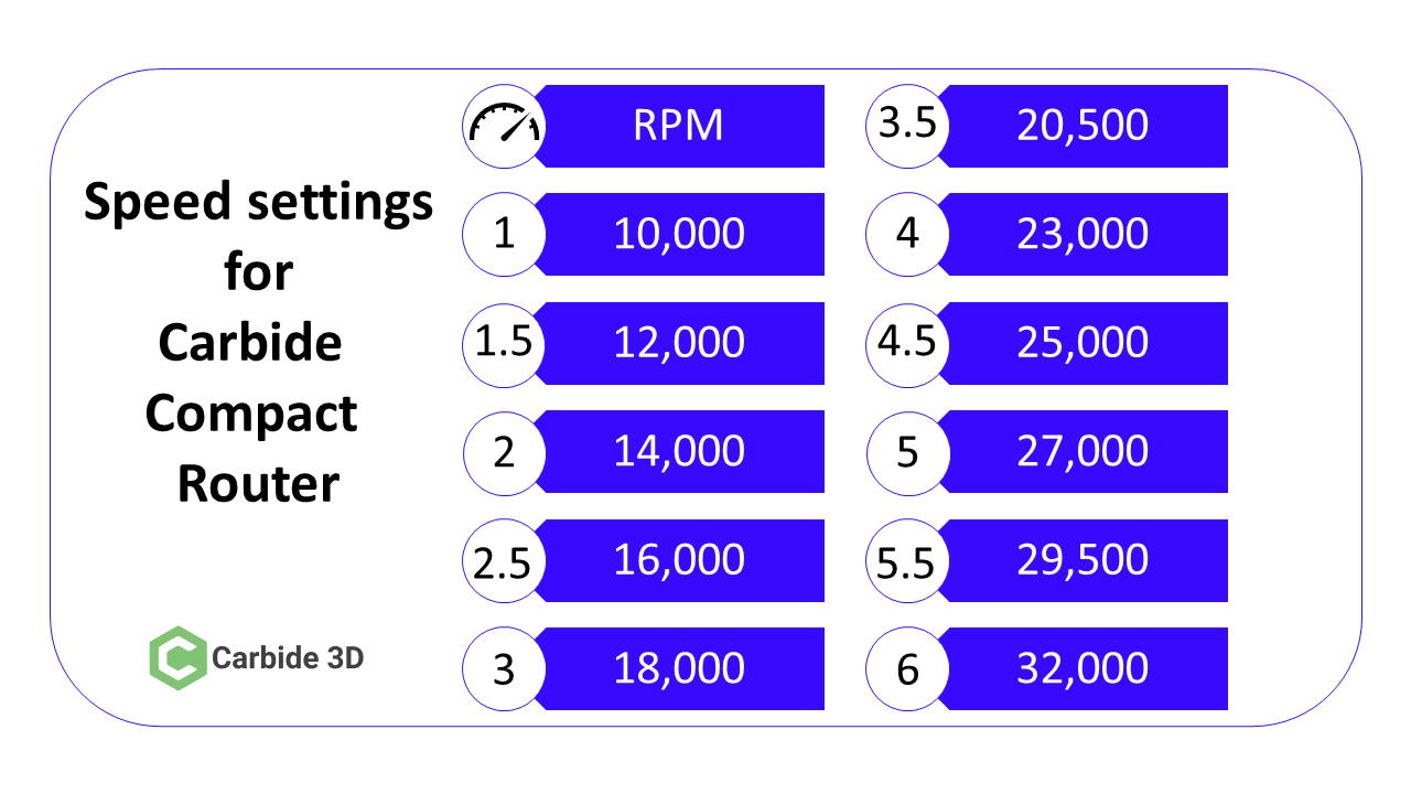
Your file has the spindle speed rather low and the depth per pass was a bit heavy, I would shoot for the recommended defaults as a starting point. For hardwood :
I don’t know what you use for a spindle but I found this helpful when I was using the Carbide compact router. I printed it on a large mailing label and stuck it on the X axis bridge.
So in addition to the speed setting, It seems that the initial plunge seems to be extremely dramatic. The router really struggles to cut and wood shavings are flying everywhere. It might be an issue with the bitzero touch probe I am thinking. Each successive cut is not nearly as bad.
Post your .c2d file, generated G-code, step-by-step notes on how you are securing your stock and setting zero relative to it and managing all tool changes, and a photo showing an attempt at cutting still in place on the machine.