Laser - Temporary or Permanent Mount?

I recently attached a laser to the Shapeoko. But I’m torn about how to mound the laser and whether to make it a temporary or permanent mount. Any Pros and Cons to either of these options?

I made a little video of the first test print.
https://youtu.be/UIabXVx31ro

1 Like

If it’s a removable mount and is always removed, then then laser will never be damaged by a crash or machine vibrations, or knocked out of alignment by an errant piece of stock.

3 Likes

You’ve got a router I presume? Mill a mount for your laser so you can run either a router or a laser using the existing carriage mount,

Can you share your collection of laser parts, PCB connections and what other G-code tweaks or controller reflashing you performed to run the Hello World project?

I’m eventually wanting to run a laser at some point and I’d want to model the success of others.

1 Like

I bought a 2.8 watt 450nm laser with a control board (ttl) included. Getting it with the board is probably the simplest way to do it. I didn’t find one for sale on Ebay again, but it is similar to this one:

http://www.ebay.com/itm/2-15W-Blue-Light-Laser-Module-450nm-TTL-12V-High-Power-DIY-Metal-Wood-Engraving-/252452884708?var=&hash=item805d0a7c7c

I also bought some safety goggles I could use with the laser. Depending on the wavelength (in my case 450nm), you will have to buy the proper goggles, you can’t willy-nilly pick some goggles. They have to be made to block that wavelength. (good thing I checked) So far, I’m not blind and they appear to work ok, maybe a little dark, but not unuseable.

Goggles I bought: https://www.amazon.com/gp/product/B01DP2HJ0S/ref=oh_aui_detailpage_o03_s00?ie=UTF8&psc=1

I followed the wiring pictures from the J-Tech website for where to connect the TTL board to the shapeokoo 3. The TTL is connected where it shows “Laser+/Laser-” in the pic/diagram.

This is a link to the pic/diagram:

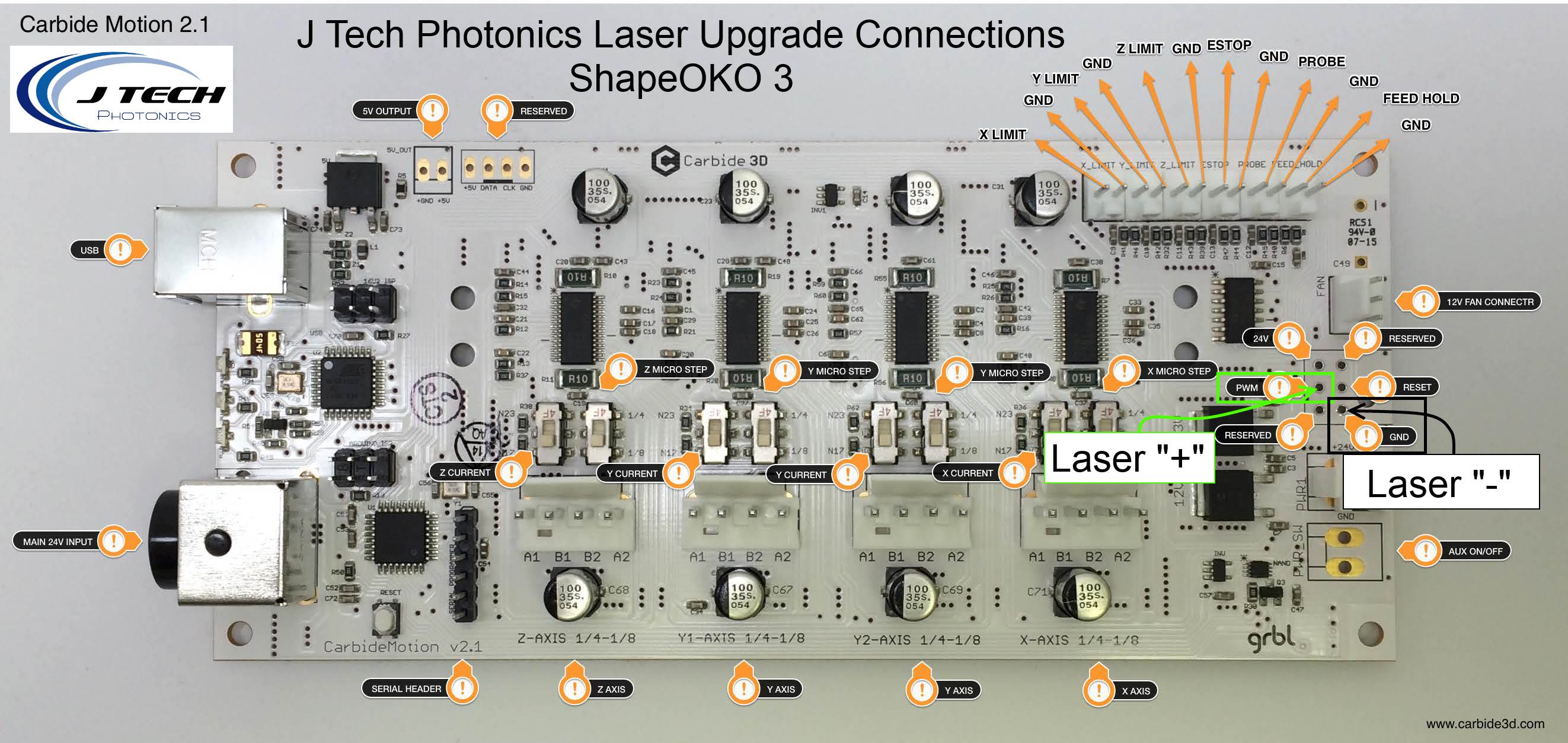
I haven’t focused it yet, but I completely intend to follow the instructions on the wiki to do that. However, I found a problem with the g code in Sttep 2: The command “g3” I believe should be “M3” and “g5” should be “M5” those are the proper on/off commands. If you want to try more lines to find a focus, then you have to copy/paste more of those lines, changing the y and z coordinates so create a new line while moving it up. Again, I haven’t done this yet, but I loaded the gcode (after I corrected the commands for on/off) so your results may vary.

Wiki Link: http://www.shapeoko.com/wiki/index.php/Laser_Cutter

I downloaded the “Hello World” file for the Shapeoko, and followed the instructions on the Wiki page (Section called “Using the Laser”). It has a link to where you take your shapeoko gcode file and upload it, it spiits out gcode you can use for the laser. When I tried to import the gcode into Carbide Motion, there were errors in the code. There was some unexpected “/” (slash) down in the code in a place or two. Once it was fixed, it seemed to work after I ‘eyeballed’ the focus of the laser (even with goggles, not sure I recommend that). The result is in the video I posted.

So far, I have not re-flashed the control board… am I supposed to?

that’s as far as i’ve gotten, work has been crazy and haven’t gotten back to it yet. Maybe tonight.

Hope this helps.

@digitaldaze -

Thanks so much for posting this information on this forum for the community. I’ve read that one needed to reflash the controller board, however your experience demonstrates otherwise.
I’ve had a laser on my acquisition list, and I appreciate this info greatly.

I have a Darkly Labs Emblaser that uses that same diode. The laser and lens assembly is a lot closer (perhaps about 1.5") to the material being etched or cut and the line width I can achieve is down to less than a hair width. I’m mostly cutting and engraving small details for model making. The attached pic shows a fish engraved on 1/32 birch plywood using the “PicEngrave” program and some N-scale (1/144) window frames cut through 80 pound cardstock using the Vectric Cut2D Laser program that came with the Emblaser. I can’t quite see what kind of a lens set-up you have in the video but like I say when the laser is focused properly at the right height some very thin cuts can be achieved.

3 Likes

Hi

What software did you use for generate the gcode ?

Thanks !!!

N-scale? That brings back memories from years ago when N-gauge railroading was my hobby. It would have been so great to have had a CNC back then to make stuff.

Hi Argenis. I use Vectric Cut2D Laser software to generate the gcode for vector cuts and engraving and PicLaser for engraving bitmap pictures. I use PicSender for sending the gcode from each program to the laser.

1 Like