Looking for some help with my toolpaths

I’ve designed a bezel that I want to mill out of wood (acacia) and I’m looking for someone to check over my toolpath before I try milling it, I’ve never done anything before 2.5d / with curves/angles before so this is a first for me (only 2d stuff). I have two bits, a flat and a bullnose (1/4 in). In my preview i kept getting ridges with the bullnose so i switched to the flat, but again that could just be me not knowing what I’m doing.

Any help appreciated, thanks!!!

F3D File:

This body shape is going to be quite hard to machine on a 2.5 axis machine like a Shapeoko or Nomad.

The non-vertical angles on the front and rear upright sections are going to be an issue, if you machine flat then one will end up with a stair ramp down it, the other would be an undercut.

You could make a fixture to elevate the front and hold the whole piece at an angle where the internal sides are vertical and those internal ramps on the sides become horizontal. You’d need to be quite careful about workholding rigidity and setting zero though.

There are a few more internal corners which will come out a bit rounded off, those at the edge of the side slot for example.

I’d suggest thinking carefully about whether you really need those different angles on the front and back, if you do, it’s probably machine a workholding fixture time.

3 Likes

You make a very good point, and I didn’t think about that. I’m rethinking the whole design now. Maybe split it in half, mill the flat part upper, and then a separate angled base? That would give a better finish on the top too as there would not be steps.

I do need all the angles… so that might be the only way to do it. Or the workholding fixture like you said, but I am also not really sure how to do that.

1 Like

What does your stock for this look like?

Are you cutting this from a single solid block or glueing up four sides and cutting from that?

It’s a single stock, block of Acacia about 45mm thick.

OK,

I’ll take a look later on today and see if I can suggest a sensible way to handle both sets of angles as those are key to your part (a stand for a mechanical keyboard if I’ve guessed correctly?).

One other question, does the internal angle cut need to go all the way to the base or just to the step where the (keyboard?) sits at half-distance?

It looks like you got other parts, (3D printed?) to support from the bottom so that space is fully internal and not visible?

Yep you are correct, it’s a keyboard housing. The base was made from aluminum and I already milled that. The standoffs are internal and will be 3D printed.

The internal angle does not need to go all the way down, just to the half distance mark really. It just can’t interfere with the keyboards PCB but otherwise it really does not matter.

1 Like

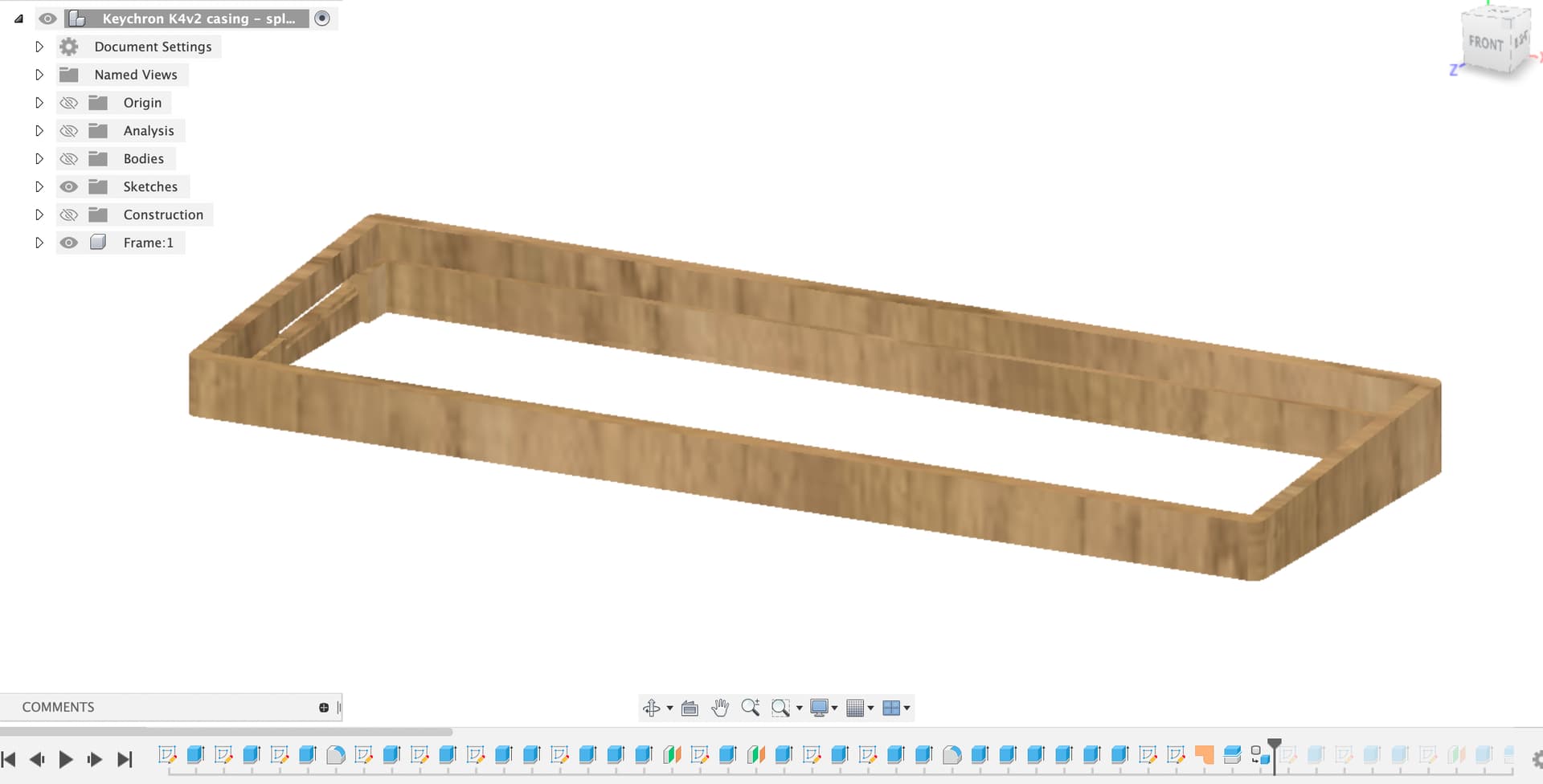
I’ve had a first go at trying to make minimum changes to make the frame more machinable.

Please check the model to see if the key dimensions are all still OK.

Working on the basis that you already have the aluminium base but not the 3D printed insert or the wood I’ve kept the base dimensions as they were.

There were a few warnings and errors in the file which is generally a bad thing in Fusion, it can lead to all sorts of unpredictable weird behaviour. I’ve fixed those and simplified a few bits of the process so it was easier to see where to make the changes to the frame internal geometry.

To see what’s been done it’s probably easiest to scroll the history bar (at the bottom) back to the beginning and then step forward to see the construction process.

This is also handy where there’s a feature you don’t want any more, you don’t have to delete it, you can just go back in the history and remove or change the feature.

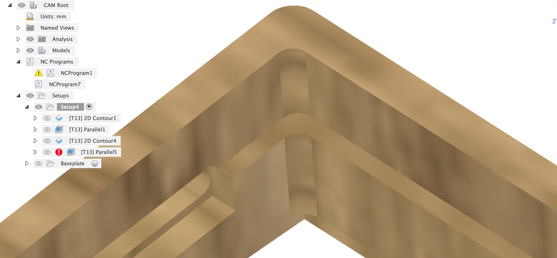
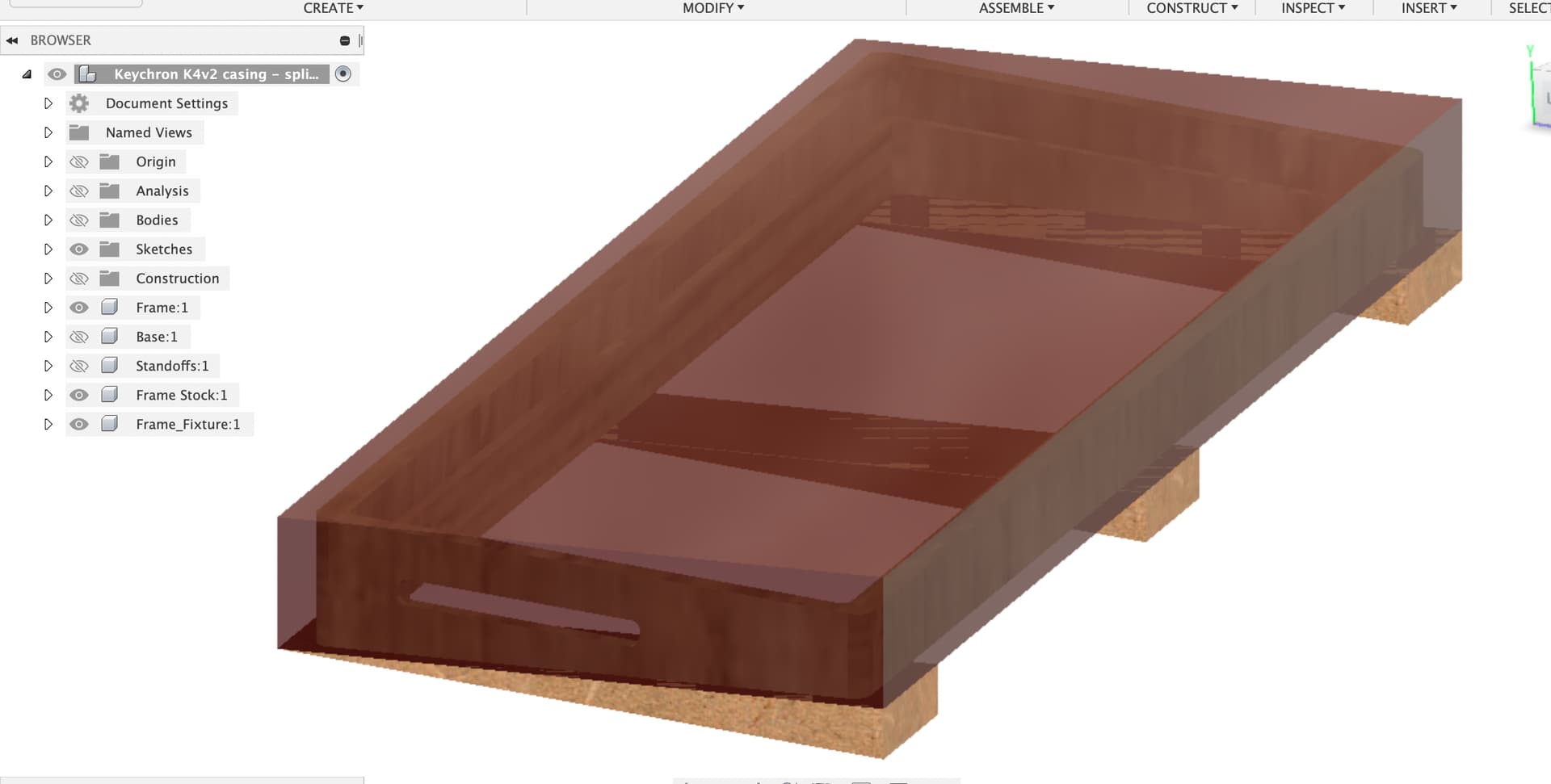
I’m not sure what the internal geometry needs to do around the slot in the side, I’ve made a few things vertical with respect to the base as well as the front and back edges of the frame

I’m not sure how you’re going to machine the end slot as the frame is too tall to machine on the Shapeoko, unless you have a vertical mount for the front overhang of the machine. You could cut a template and use a hand router with a bearing follower bit for this.

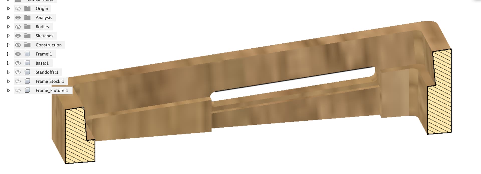
I’ve created bodies for the stock and the fixture

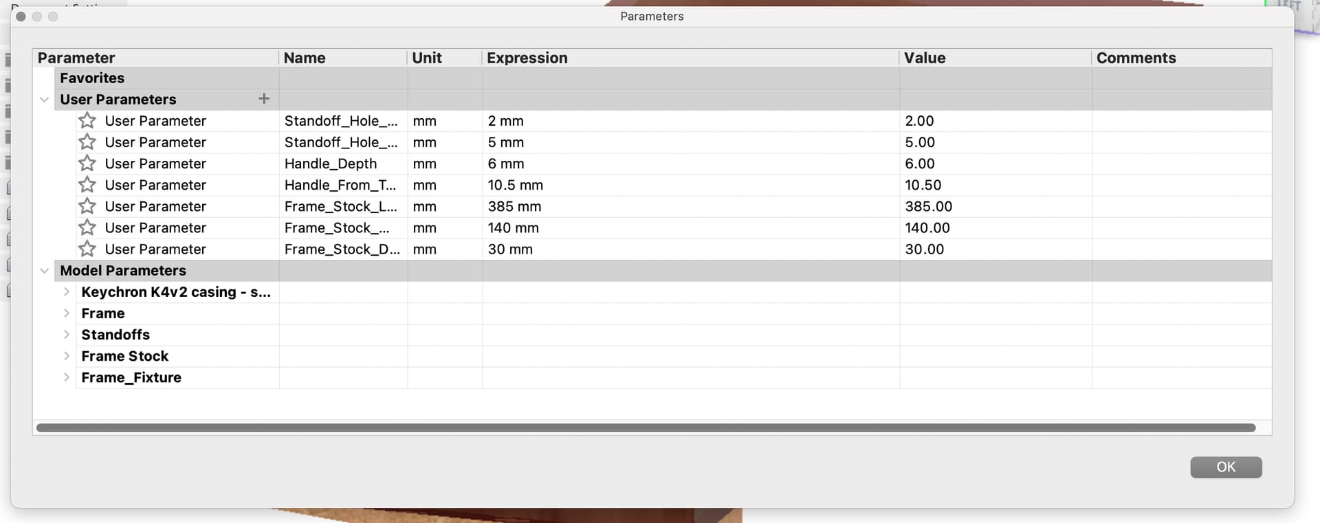
I’ve put parameters in for the dimensions of the stock to make that easy to change (modify / change parameters)

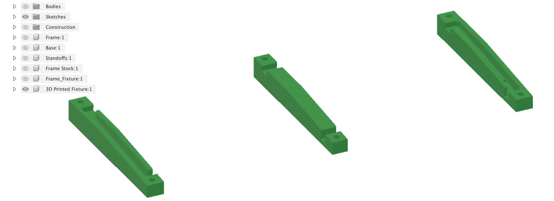
I figured the simplest thing to do for the angled cut on the top was to make wedges to stand the frame on. I would probably make these out of a few layers of MDF and cut them on a table saw sled, alternatively you could cut them out on the Shapeoko. The only important thing is the angle.

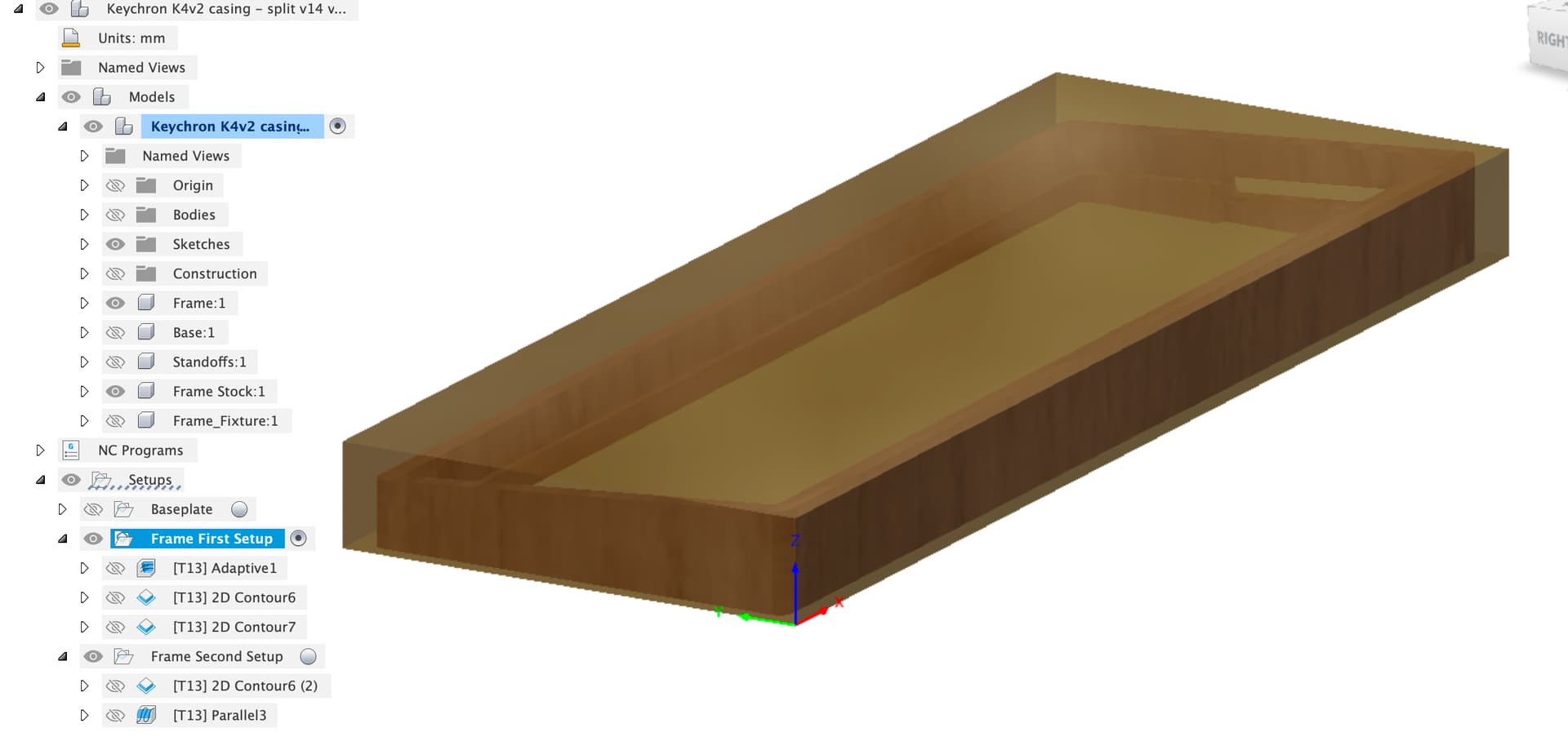
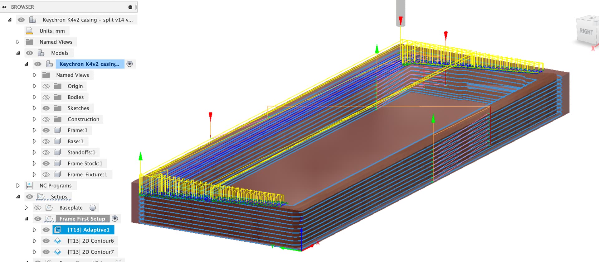
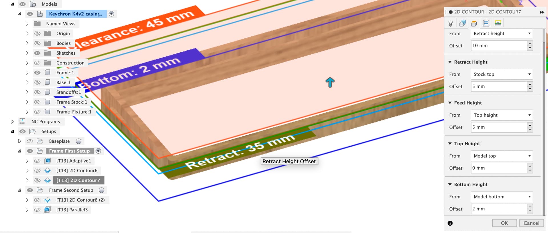
For the first CAM setup I have the frame ‘flat’ and the zero set at the spoilboard.

There’s then an adaptive clear on the upper part followed by 2D contours inside and out. I’m not sure what to do for workholding here, I’d try blue tape and superglue.

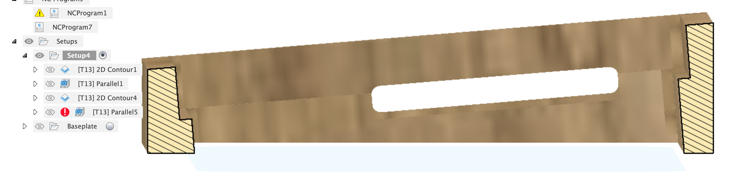
This set of jobs leaves 2mm uncut at the bottom of the inner slot, I figure cutting this out by hand and then sanding might be easiest, you could try all the way to the bottom with tabs or other approaches.

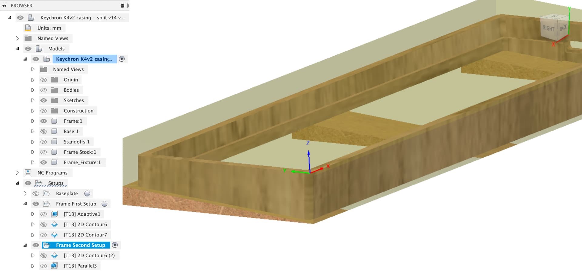
The second setup uses the wedges to hold the frame at the wedge angle, zero has moved and needs to be set off the cut outer edges from the first setup.

Getting the X aligned correctly will be really important as any misalignment will really show up. I suggest putting a dial indicator in the spindle and jogging left / right along the front machined edge to get it properly straight with the Shapeoko X axis.

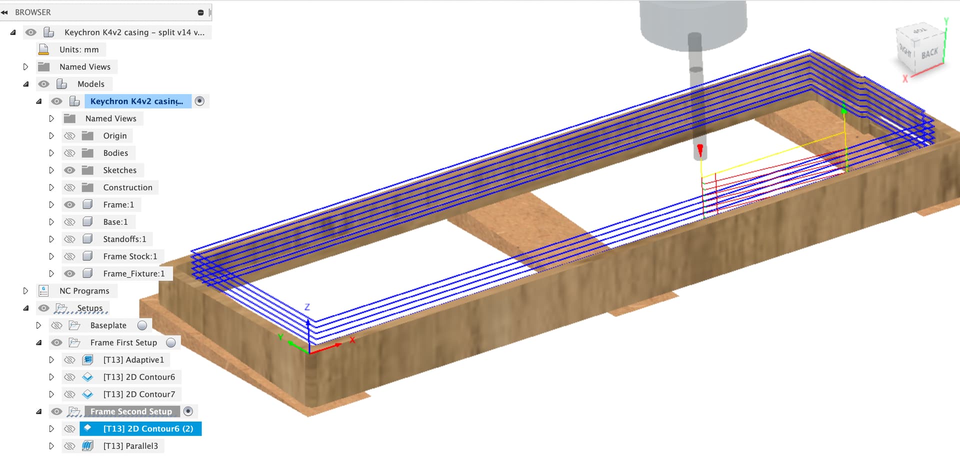
There’s two toolpaths, a contour to cut the inner angles, for this one, I might do a first pass with, say 1 or 2 mm stock to leave, then measure how accurately it is centered in the outer cut.

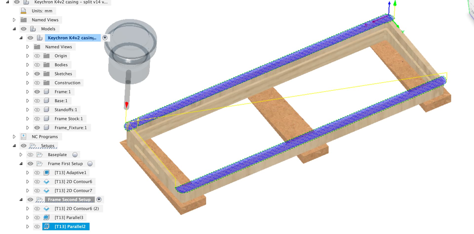
Then theres a parallel finishing toolpath for the top face

Which brings us to the problem, workholding, there’s nowhere left to hold the work down. You could split the top finishing into two toolpaths which might let top-clamping work.

For the holes in the bottom I might just mark through with the baseplate and manually drill.

Hopefully that’s some ideas to get you started on the wood machining, I’d try the toolpaths out on a test piece of cheap wood first and find out what the problems are and what workholding is going to work.

Keychron K4v2 casing - split v14 v13.f3d.zip (1.6 MB)

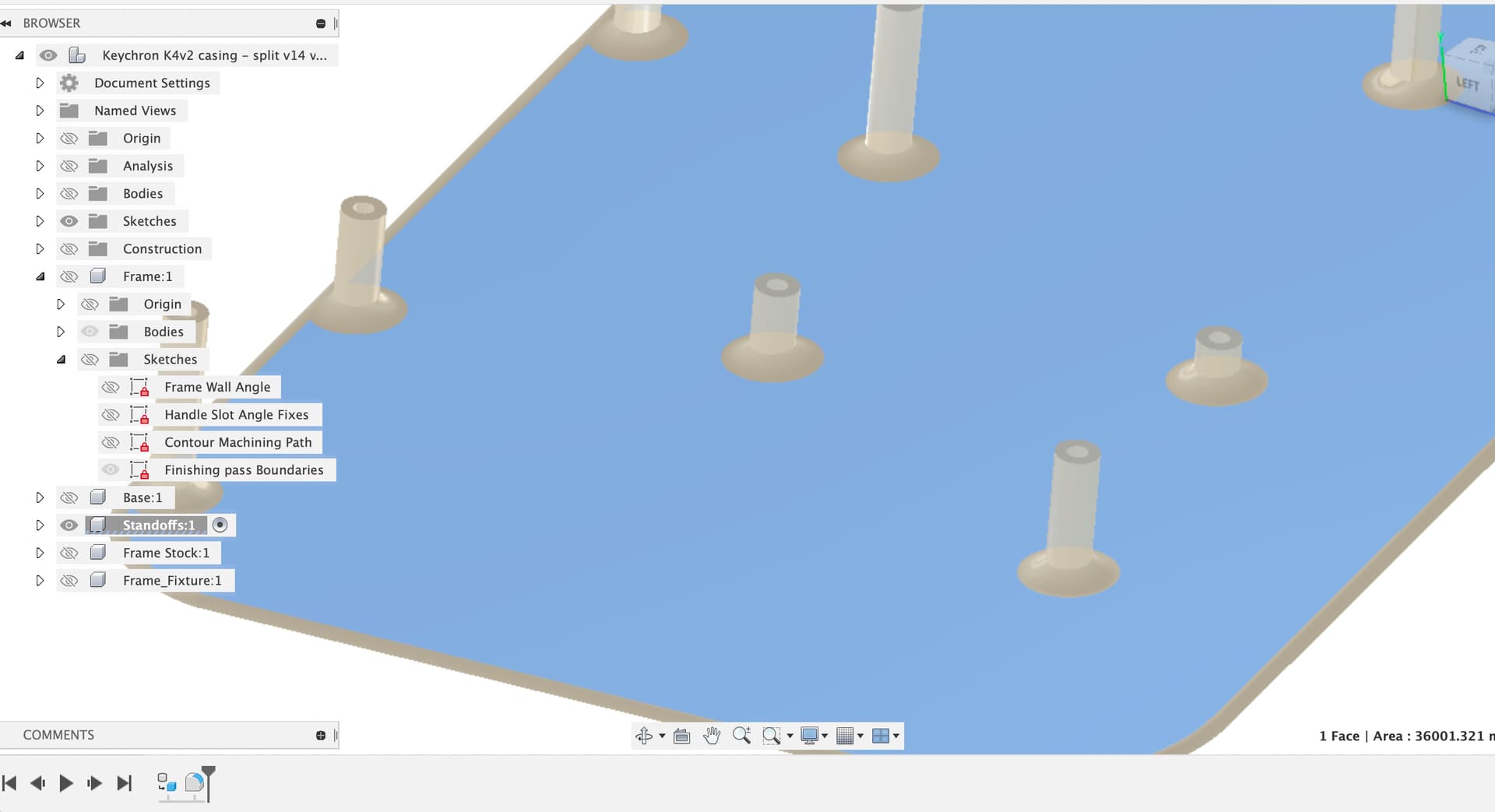
One final note, I wasn’t sure if you wanted to keep the fillets at the base of the standoffs to reduce the tendency to snap off at the layer joints when 3D printed, I put them into the Standoff component, you can delete or suppress the feature there (Selecting the component filters the history bar to only the features for that component)

2 Likes

Sounds like you could use a sin plate.

1 Like

Depending upon the angle you might be able to use Shims and a straight-level to create the desired angles.

does anyone see where I am going with this?

NVM disregard this…lol

I just saw the power-point above… it features this exact thing :grin:

Wow, this is amazing!!! Thank you so much for the help. I still have to go back and double check all the dimensions again, but this looks great.

  • For the end slot, yeah my plan was to just make a template and then cut it by hand.
  • The wedges are a brilliant idea. I could probably just 3d print the wedges too to ensure they are all identical / have the correct angle, right?
  • For the standoffs, yep I did want to keep the fillets to avoid snapping. For some reason I could not figure out how to combine them back into the standoffs feature (i kept getting an error which you did mention)
  • I agree for the bottom just marking and drilling is the best option, that was my original plan.

I will have to spend some time learning from the changes you made, and I probably need to get a scrap of wood to test on before i run the real thing but this is super helpful!

1 Like

Since you have a 3D printer, you could print a test version of the wood frame in speed / draft mode to check it all fits? I’ve done this with quite a few larger aluminium parts and saved myself some scrap… :face_with_head_bandage:

Nope, that there is the good idea…

Since we already have a Fusion model of the wooden frame, we can set up a couple of offset planes, extrude a few PLA fixture brackets and then use the wooden frame in a boolean subtraction (combine / cut in Fusion) to give us most of the shape we want.

A little tidying up and we have a set of brackets which are printable and can either be stuck or screwed down to the spoilboard to hold the wooden frame for machining the top angled side.

You’ll still need to hold the wood down for machining but this is likely to help stop it chattering. If the test piece is too weak and chattery you could trim out the inner parts on these fixtures and not remove the central block of the wood until all the machining is done. (those 2mm at the bottom of the first set of contour cuts)

Edit - it might be good to use the offset face command in Fusion on the edge walls of the fixture prints to give enough clearance for the wood to sit in place, maybe 0.1 or 0.2mm.

Glad it was helpful, if you’ve got questions about any of the CAD or the toolpath containment etc. ask away, there’s are almost infinite different ways to do things in Fusion and what I’ve done may not be obvious (or even particularly sensible).

Keychron K4v2 casing - split v14 v15.f3d.zip (1.8 MB)

4 Likes

Awesome! the brackets are great!.

I’m going to 3D print everything to check the fit and then hopefully start milling a test piece. Thanks again this is super helpful

2 Likes

I printed the new changes and it fits pretty well. I may add half a mm spacing on either side just to give some wiggle room for the PCB to sit. Thanks again for all your help, just need to make that tweak and then i can start milling!

2 Likes

This topic was automatically closed after 10 days. New replies are no longer allowed.