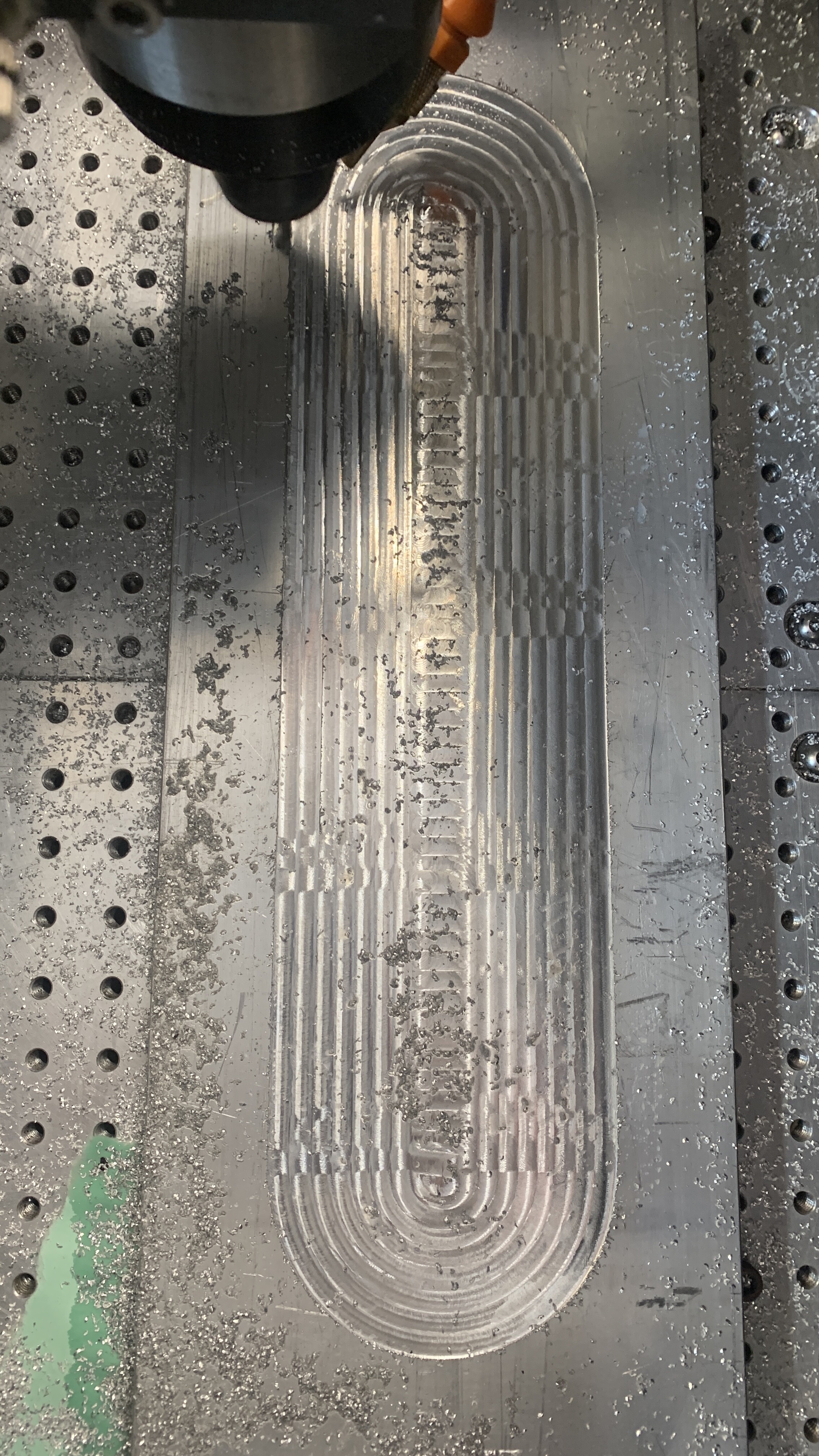
Ive noticed this since the first time i leveled my waste board, I have low spots and I assume high spots between even intervals along the X. I normally do smaller projects so it’s never been an issue but with this aluminum part maxing out the work area, it was very noticeable. I assume the wheels are to blame? Ive replaced all my wheels and axel bolts since Ive had the machine, so I guess I am doing something to cause the issue.
When was the last time you trammed (squared) the Router?
I just calibrated everything before this project because I knew it was going to stress the machine. Ive never been able to get a good read on the Z / Y because of this problem. If i drag an indicator across the table I can measure a +/- .006" across the areas.
I have an HDZ and spindle, so it’s also a challenge to keep the head from sagging towards the front of the machine, but thats a separate problem lol.
First, check to see how much flex you have in the spoilboard, they move around quite a bit on the larger machines unless you fix them down to something solid.
On the tramming front, I put a big clamp on the X rail, then loosened the bolts holding it to both Y plates and used the clamp to rotate it back to get the Z closer to vertical as I had the same sagging forward. That didn’t quite get all of it so I stuck some small shim plates on the lower V Wheels to complete the tipping of the HDZ back to vertical.
Is that row of distinct bit marks where the toolpath steps down on each pass?
I’ve got an S3 with an aluminum base, so the flex is minimal. I get those dips even in MDF and I have tuned this thing in as much as possible. The only inconsistency I notice is in my concentric nuts / V wheels. When I tighten them, it’s either a bit too snug or i’ll find a loose spot when spinning the wheel.
Since the spindle and HDZ are so heavy, it feels like I have to “over tighten” them just to get it held up. (according to the it should still spin method)
A few months ago I did my first full maintenance since buying it. I replaced all the belts, wheels and hardware holding them to the machine, and the issue was still present. I chalked it up to the tolerance of the machine / how concentric the wheels are. I was expecting a few people to say Yeah mine does that too.
1 Like
I have measured and others have also observed that the V Wheels develop dents when parked for a while, especially when they are tensioned up to try to stabilise the Z axis. These do seem to recover when the wheels move.
As you tension up the V Wheels it does reduce the wobble a little but at the cost of this deformation, backlash and uneven X travel which is easily mistaken for belt inconsistency.
On my machine I backed off the tension on the V wheels and made sure that I had the machine move around for a while before starting a finish cut (roughing passes are good for that) to let the dents recover in the V Wheels.
Quite small amounts of crud on the axis or wheels can also cause noticeable surface finish issues, I was surprised how small.
It’s worth separating what may be a tramming issue where the Z is not vertical from the V wheel bump & wobble issue. I started by getting my Z axis and spindle vertical by using the left / right adjustment on the spindle mount and shim stock to space the lower V wheels until the Z was vertical. Once that was all in line it was easier to see what other problems I had.
Here’s a thread about the V Wheel shimming
1 Like
I read that over and watched the video, I’ve definitely seen that one, but it’s always good to refresh. Over the weekend I got some steel core belts, so I tore the whole machine down and rebuilt it. I shimmed some areas and definitely got it closer than it was before. Using a piece of glass over a surfaced waste board; I put a coaxial indicator in there and got the Z squared within .0015" over 5".
I had to shim the bottom wheels of the HDZ to bring the Z carriage square to the X. Originally the concentric nuts were tight even in the most open position, but after shimming its better, but only one wheel can be loosened enough to spin freely. They are now tensioned enough that I can move it without spinning. If they’re any looser, i can lift / deflect the Z axis.
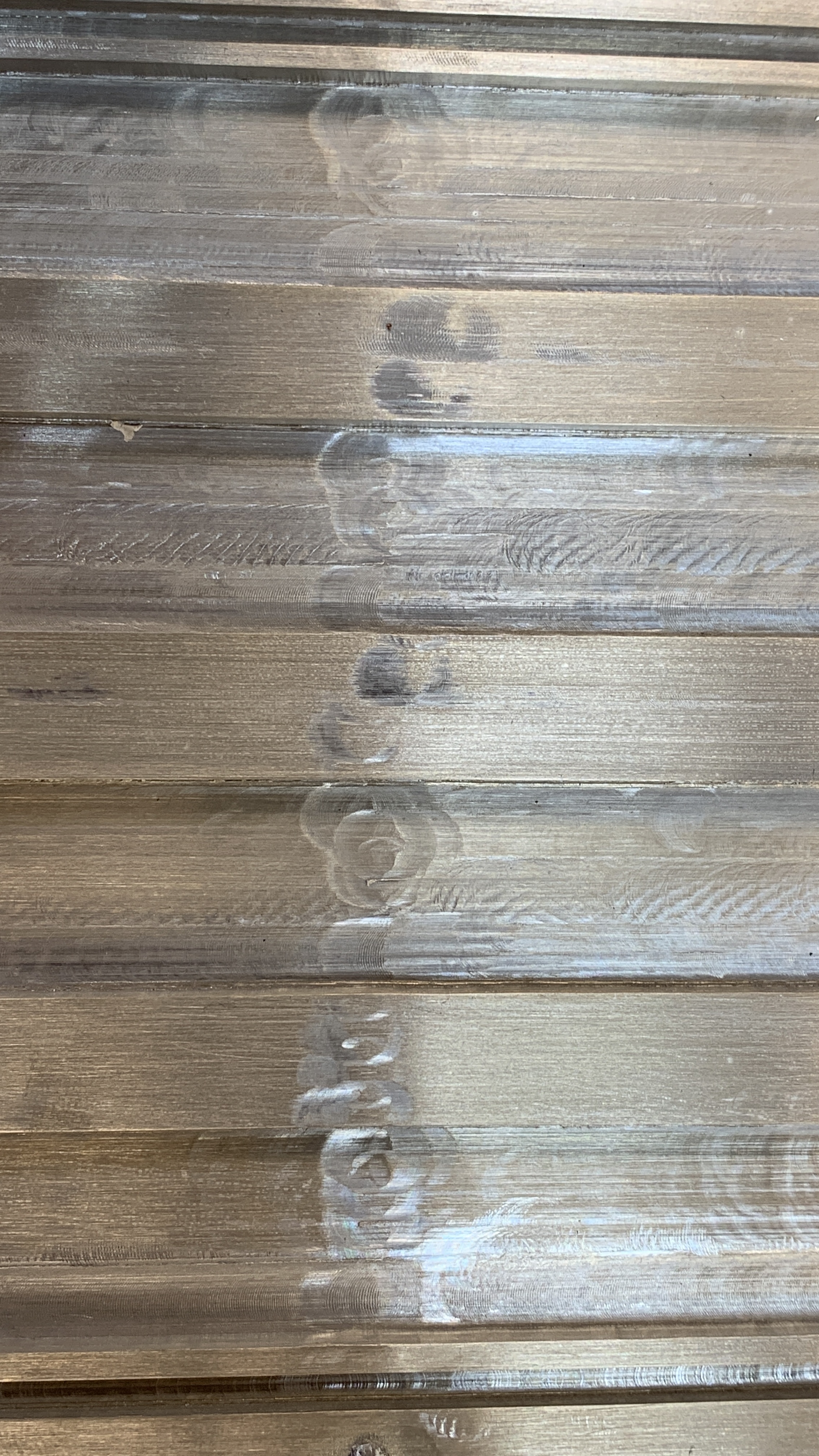
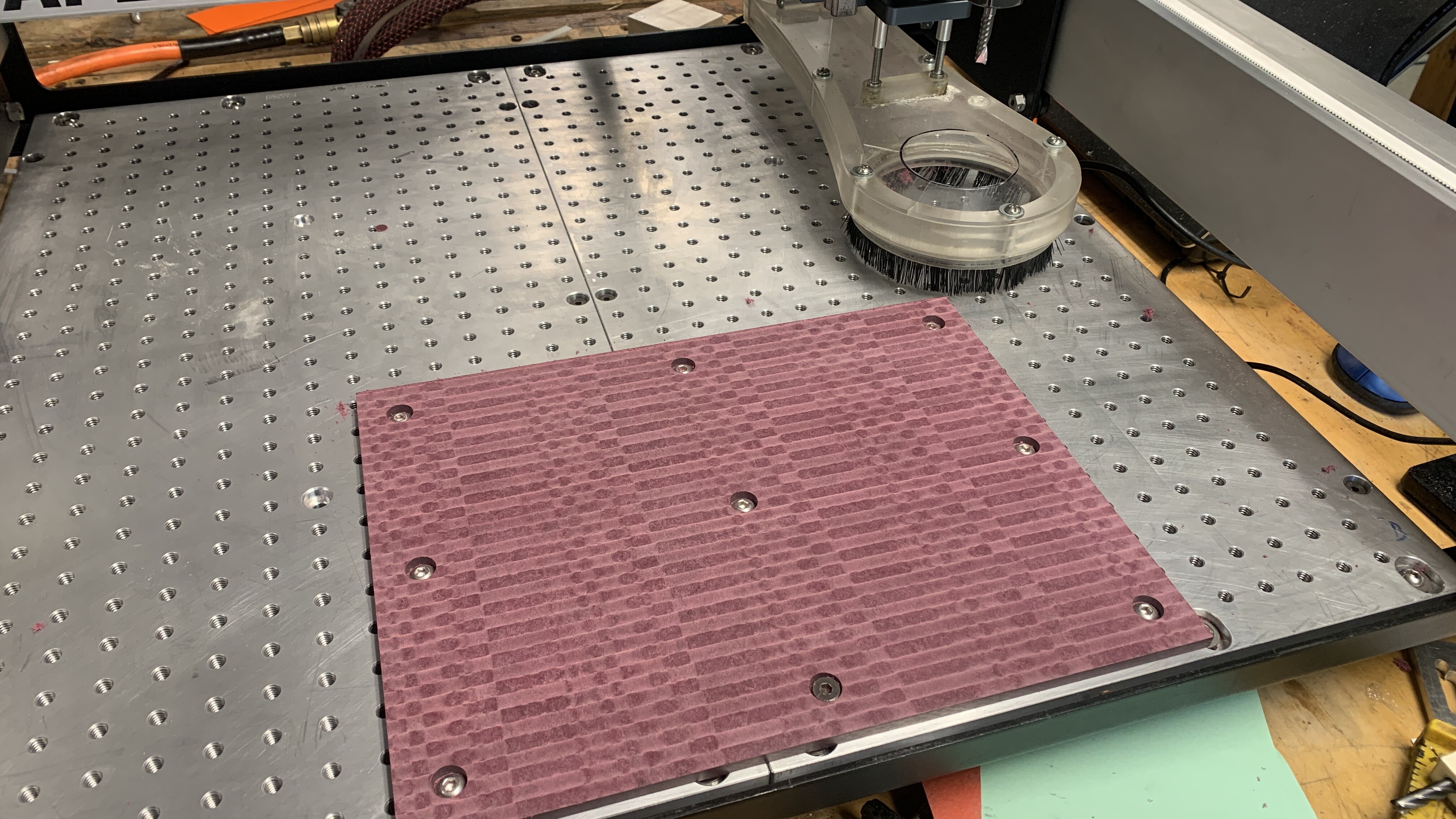
After a test run, it was overall noticeably better, but now the pattern I’m getting is different. This is a piece of richlite, which is my most commonly cut material. Got any pictures of what a faced waste board looks like on your machine? I replaced any wheels that had intermittent contact, so I’m not sure what else I can do.
1 Like
That sounds like good thorough work.
The richlite now looks like the sort of finish I get on Aluminium if I run a facing toolpath on it. Is there any measurable out of flat on the richlite or is it just directional marking in the surface from the cutter?
Do you still have the deep divots that you were getting on the Aluminium plate?
This topic was automatically closed 30 days after the last reply. New replies are no longer allowed.