I am trying to figure out how to orient the project’s lower left to the material’s lower left so I can use the bit zero without having to jog the bit over to the middle of the material and HOPE to gods of sawdust that I am over far enough that the project fits because carbide Motion does not have a run boundary feature- which is amazing in itself. I saw there was a thread asking for it, but it has been removed and haven’t seen it requested anywhere else. I figure they expect you to reference off lower left, but I haven’t found how to do it in fusion 360 yet. Carbide Create can’t import the stl models (topologies) so unless there is a way and I missed it, Fusion 360 it is for now. What is the process? Anything I try, puts the center of the topology on where ever i set the X0,Y0 and that renders the bit zero useless.
I think the machine has issues. The first project I ran, the router would raise up 10-20mm and stop. Wouldn’t take any commands, had to restart the machine and cncjs. Thanks to Youtube, I plugged the machine into a surge protector and made it through the project without issues. My garage has its own break panel and the only other thing running was the Festool CE26. Today, something made it try to launch my router to Mars. Somehow, the machine got stuck on a command (running a dedicated 2011 macbook pro 13" as the controller) and by the time I got to the machine, it was saying 457mm and climbing for the machine Z and work Z. Pretty sure that motor just entered its retirement age.
I accidentally hit “like” on this post but can’t remove the like… not that I don’t like the post, but I don’t particularly like it.
Anyhow. I’m not a Fusion360 user but I’m quite certain the answer to your first paragraph’s question is question is to “set the stock size in fusion360 and also set the origin to the lower left in fusion360”.
As an aside, if you are able to determine the stock centre and jog to the centre of the material (as you seem to suggest), then you are solving your problem too. The BitZero is not useless in this scenario since you can manually set X/Y to the centre and then use the BitZero as a Z probe only.
For the soft limits issue - if you are happy keeping the stock centre as the origin, put the stock centre in the middle of the machine (where the rapid centre position is). If your stock and model is wider than it is long, put it lengthways (landscape orientation).
You mention Carbide Motion doesn’t have a run boundary feature and hope that doesn’t cause issues with your cut - but then say you are having problems with the machine and had to restart cncjs. Knowing which one you are using would help the answers to the second paragraph’s questions.
Hi Jeff
Did you contact support@carbide3d.com about all this yet ?
(the community will provide tips, but your primary channel for support should be the support team)
Sorry about the like issue. Weird that you are not able to unlike it but I know now to be judicious with my likes.
I orient the topology stl’s so the lower left corner is at the 0,0,0 origin in 360, but Carbide Motion, CNCjs, and Luban (I have a Snapmaker as well) all orient the model path’s center as being 0,0 when it is time to manufacture. CNCjs and the Snapmaker controller allow you to run the boundary, which is great because it helps align clamps so they don’t get bit. CM, not so much. You have to remove the material and start the job to see where it wants to go.
I see what you are saying the bit zero, but using the bitzero is not a fast process if I am having to reset the x,y anyway once I find the ‘center’ x,y of that material with the jogging. Setting the z from the material is a few jogs away. I don’t run the risk of having to start completely over at the initialize machine step if I forgot a step and the probe fails.
Sorry for the confusion on the switching of CM and CNCjs. I think CM is missing a lot of features that seem logical to have, and I’d like to stick to one (preferably CM since its made for the Shapeoko and I am still learning its quirks) but I need to figure out how to get the model 0,0 material 0,0 and work area 0,0 to align, which then I’ll have a better idea of where the boundary is without having to a lot more steps in zeroing, placement, clamping, and praying.
Thanks for the response. I haven’t talked to them yet about it since cncjs was running the machine when it happened and its that ‘use at your own risk’ disclaimer. I want to run CM and see if it happens, but I need to work out the orientation piece so CM is more tolerable to use. Since CC cant use the topology stl files to create the tool paths, I don’t think they’d help with Fusion 360. I might post on 360’s their forum as well, just thought this has to be a common workflow to start at the lower left 0,0, and someone knows how to set 360 to make it happen.
When you create a Setup in Fusions manufacturing workspace, you can place the WCS origin anywhere you like. A point on the model, a point on the stock, or an arbitrary point anywhere you wish using an additional point or sketch in the design space.
Though generally simplified in programs like CC, Vetric and the like, this is true of every cam space I’ve used.
Thanks Lowbrowroyalty. I am updating a tool path as I type this setting the wcs to the 0,0,0 origin point. I only started this a few weeks ago and I have left it as the default ‘model’ since I didn’t have to consider indexing from lower left in Luban.
Its the where to say “… zero point” part that was eluding me in fusion 360. I left the wcs as the default ‘model’ so that is where the problem was. Never had to think about lower left since Luban lets you jog the boundary and I was ok with it being in the center of the material. New machine, new software, new workflows now.
I’m trying to work through the introduced learner’s curve/user error’s first and work with it as designed before I hit them up. I think the wcs will solve this problem so I can start debugging the others. Thanks for the tip on Pro. If 360 decides to be a pain, I’ll take a look at it but for now, my internal ram is maxed out with all of the different software quirks I’ve got going.
My pleasure. Capable CAM tools like those included in F360 require a little time to develop familiarity. But, in my opinion, it’s worth sticking with. The reward is far more flexibility.
Start with Setup and gain familiarity. Then move on to your relevant operations. F360’s cam environment windows are generally well organized. When using any window for the first time, just start on the far left tab, and work to the far right tab. Examine each option. If you don’t understand the option hover your mouse over it for an explanation. The simulation feature is a wonderful tool to develop further understanding of changes.
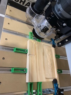
Zeroed the bit using the bitzero (got the x, y: 10, z:19 standards). x,y,z zero looks good.
Loaded the new gcode and ran the job. It took the x,y that was set from the bitzero as the middle of model and took off cutting the right side of the topo. I let it cut to demonstrate the orientation issue.
From the gcode:
(puerto-rico-clearing)
(T1  D=6.35 CR=3.175 - ZMIN=4.334 - ball end mill)
G90
G17
G21
(When using Fusion 360 for Personal Use, the feedrate of)
(rapid moves is reduced to match the feedrate of cutting)
(moves, which can increase machining time. Unrestricted rapid)
(moves are available with a Fusion 360 Subscription.)
G28 G91 Z0
G90

(Adaptive2)
T1 M6
S18000 M3
G54
M7
G0 X164.913 Y14.159
Z25.333
G1 Z12.833 F1778
...
I’m missing something, and probably something obvious.
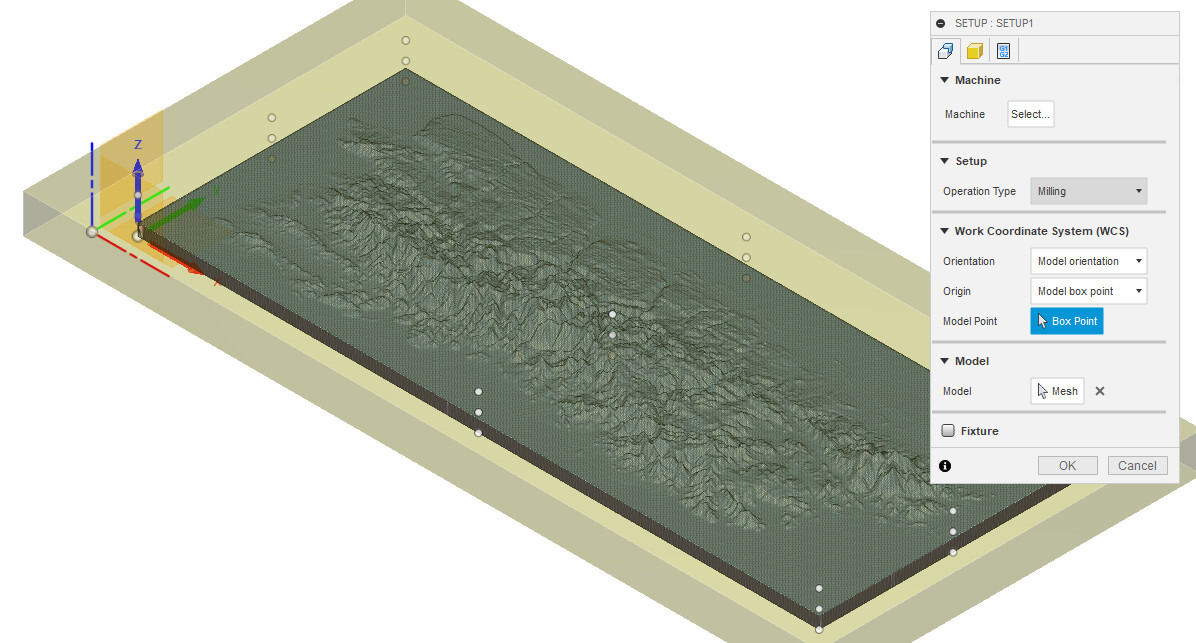
You chose to use the model orientation, but it doesn’t look like you selected a point to set the zero.
I would have used stock orientation, and selected one of the box points of the stock.
Are you positive you did not mix gcode files, or regenerate to the same target filename and for some reason F360 would have failed to generate the gcode ? Upload the gcode file for a check (that should reveal that it does not match your screenshot)
Trying to follow the recommended means of responding to multiple folks. Hope this is right.
@Steve.Mc I selected the origin point of the model- which placed that second thicker blue green red origin so I thought it selected it. (360’s lack of user feedback is frustrating- Many times I’ll be clicking on things without response and getting mad only to realize that I am still in orbit mode) I even selected other points to see what it would do and it moved the bgr origin to that point so it is ‘selected’ as far as I know. It would usually throw a fit if something isn’t set like disable the ok button? But it successfully posted the gcode so I don’t know.
I didn’t think model orientation would have any effect because it “uses the orientation of the current part for the wcs orientation” and I want the topopgraphy on the Z, X and Y are where they need to be, so I don’t think that this setting effects where the wcs is.
I can try changing the model orientation to stock, but I need to have room for the clamps and don’t want it to start at 0,0 on the stock. Without being able to run boundary, its a guessing game if it will start there and hit all the clamps. Only have to do it once though right? Hope that makes sense.
@Julien - I thought I grabbed it too soon before google drive did it’s sync thing on the macbook controlling the machine, but the last modified time stamp checked out. Just to be sure after my first go, I posted the program again and made sure the drive synced before I uploaded it to CM. It followed the same wrong path. To rule out it possibly not writing, I renamed it (just now) and it is identical to the earlier when compared in VS code. Same info as I pasted above.
I am going to trash this project and start completely over. 360 being in the cloud and all, just another layer of possible issues.
The reason I asked for the full Gcode file was to preview it in a gcode visualizer, to see where the zero with respect to the toolpath in the actual gcode file you ran. It’s very hard to tell from just the few first lines you inserted above. Actually you can (and should) do this yourself as a habit of double-checking the gcode before running it. Just pick one of the available Gcode viewer, load your file, and visually inspect where the toolpath stands with respect to the zero point. The most popular offline one is Camotics, and a good online one that I use all the time is ncviewer.com. If the work offsets in the file are not what you expected, you will see that instantly, without having to run the job on the machine
What you did in Fusion360 should work, the red/green/blue X/Y/Z arrows do show that you selected a corner as the zero reference for your toolpath. The only “mistake” in the case you showed, is that it seem to be set at the lower left bottom corner of the piece itself, not anywhere on the stock, and I have a feeling that this is not where you physically zeroed the machine (since it’s physically impossible to jog the cutter to that location before running the job). Still, it should not shift the work by half its total width. What you usually want to do is pick the top left corner of the stock as the zeroing point (that’s where zeroing with a probe is the most convenient). Alternatively, for designs that have a natural center that must be located precisely, choosing the center of the top of the stock is a good choice too. Choosing one of the stock points on the stock bottom works fine too in cases where you want to ensure you won’t cut into the wasteboard, and you are unsure about the precise stock thickness.
Let us know if you figure out why it wasn’t working for you, but you are on the right track.
Oh yes, I’ve used ncviewer a few times to figure out what line of code I can start with when I had to stop the project. I’ll have to check out that Camotics. I’ll be remaking the model in 360 today and will let this thread know what happens and will try the stock this time.
 )
)