Thanks Mark, will be trying that. I’m running through everything in great detail, and noticed this is meshcam. It looks as if zero point lower left actually zeros me to upper left. Selecting lower right zeros me to lower left. Please refer to pictures.
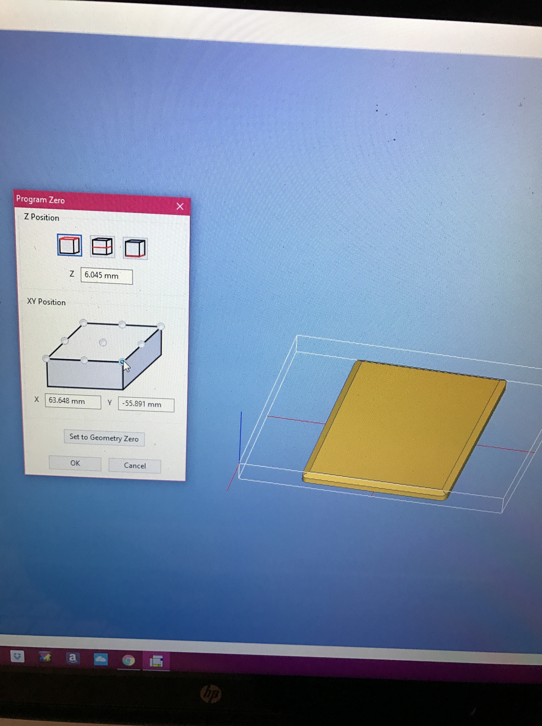
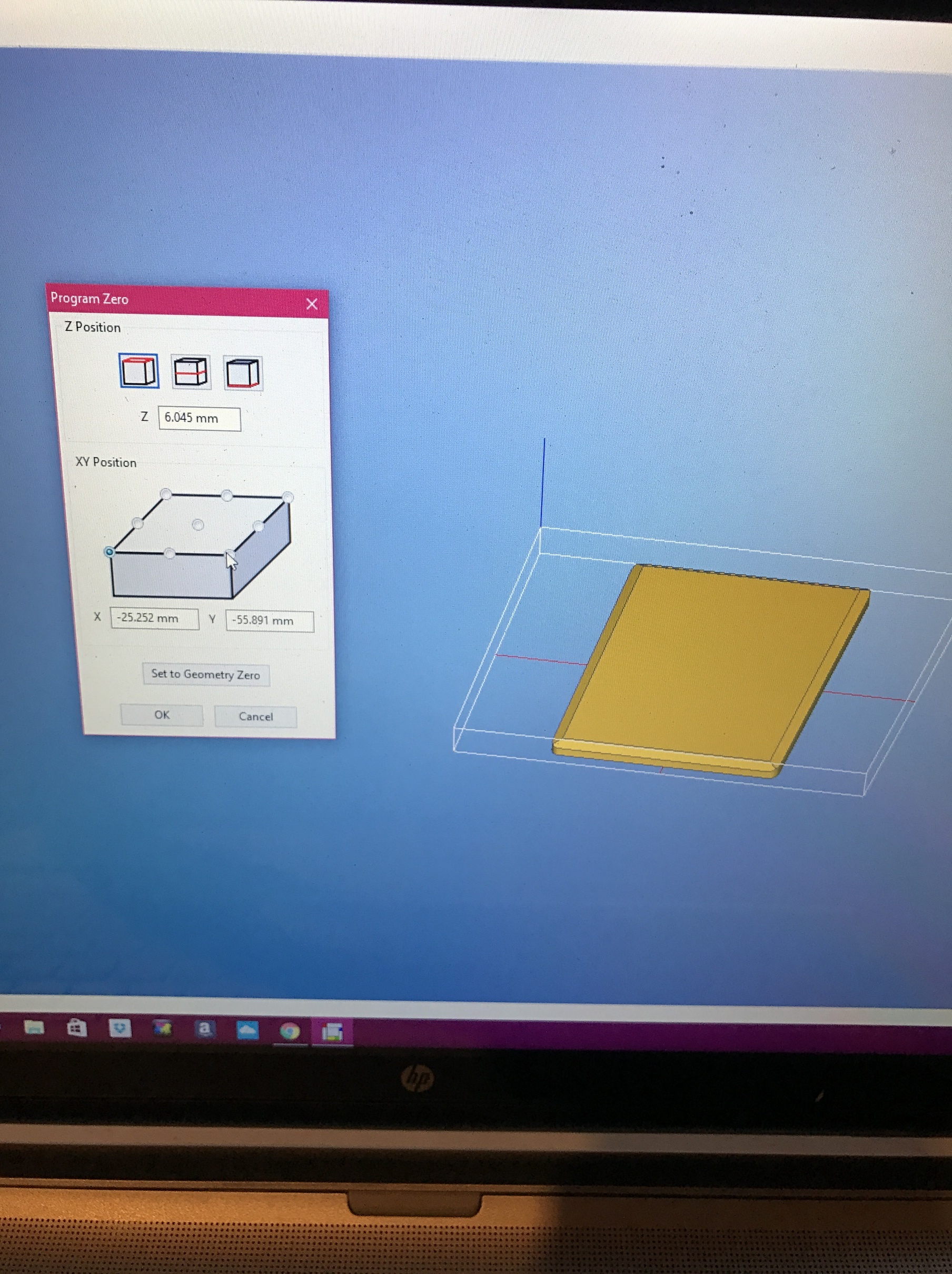
Looks like your view is rotated around the Z axis 90 degrees or so. The X axis is pointing toward the viewer.
@markwal
Thank you so much! I moved Y 0.35mm and I have damn near perfect alignment. Next go will be 0.38mm and I think it will be spot on. I wish @ApolloCrowe would chime in. There is an obvious issue with my machine not centering Y when rapid move to center. What will you and your team be able to do to help me solve this?
Edit:
I notice when doing rapid to center and clearing all offsets y is 107.39. I was damn close setting it to .35. I have a nagging suspicion that adjusting to 107 by moving .39 will put y dead center.
The remaining question is how can I set this position to memory so I do not have to do this each time I set up for two side job with flip jig.
My #111 is -107.08 (It’s on the Settings tab.) You moved Y toward you though, right? I think then it would be 0.38mm or 0.39 more. I think the table coordinate system is stored in G59. You can see it when you type ‘$$’ or ‘$#’ in to the MDI edit box with the Log window up.
Since it looks to me like Carbide Motion tries hard to keep you from messing with these settings, you should probably send mail to support@carbide3d.com and ask them how to adjust this Y reference value. (You can actually send a properly formatted G10 to Grbl to do this, but I hesitate to put a command line down here since it would be easy for me to make a mistake or some other reader and stomp on their reference points or other settings and it might be hard to be field recoverable. I think that might be why CM doesn’t want you to stomp on them easily.)
I have many positions that I need to remember (different vise positions, etc.) so I leave a Word document called POSITIONS on my home screen and there is where I store these positions along with a brief discription.
Over the past year, I probable have 8 or 9 stored positions that when I need, I open the document, and then cut and paste into a MDI line.
@markwal
Yes toward me. I am so close with moving .35. I feel an extra .38 would overshoot. I have a suspicion an extra .04 would put be spot on.
@RichCournoyer
You’re right…probably not worth trying to rewrite the default y. It’s all a part of machine setup.
Nah. I meant 0.35 or whatever you decided subtracted from -107.39. So your new Y reference offset would be -107.77 or thereabouts. You should be able to see that if you clear all offsets just before you are going to set your Y zero. Which might be what you want to write down in your Word doc.
-107.74 is good. Can feel a hair line ridge with my nail so now begins the daunting task of dialing it in to perfect zero. I will be making a press fit part and will need to rid my work of this ridge. Any tips besides playing around with small adjustments at this point?
Slightly off topic, but it relates to alignment. Particularly z axis of the part and accurate part tolerance as I have modeled it.
When using .500" thick project board my tolerances are quite good.
When I cut .250" thickness off of one of my stabilized wood blanks there is some slight height variation. .225 to .255 roughly. The tolerances in the final part are very slightly off.
When inputting material dimensions in meshcam is it best to use the lowest found number of the material or the largest?
I am cutting with a miter saw which is not ideal. I am losing valuable material due to blade width. I think I may begin to use my band saw. Which method of cutting wood blanks is ideal for work on the mill?
Thanks.