By request:
Drawer say w: 12", h: 4", depth 16". Let’s make the drawer face 14x6.
stock thickness
- sides 1/2 in.
- Face 3/4in
- bottom 1/4"
By request:
Drawer say w: 12", h: 4", depth 16". Let’s make the drawer face 14x6.
stock thickness
- sides 1/2 in.
- Face 3/4in
- bottom 1/4"
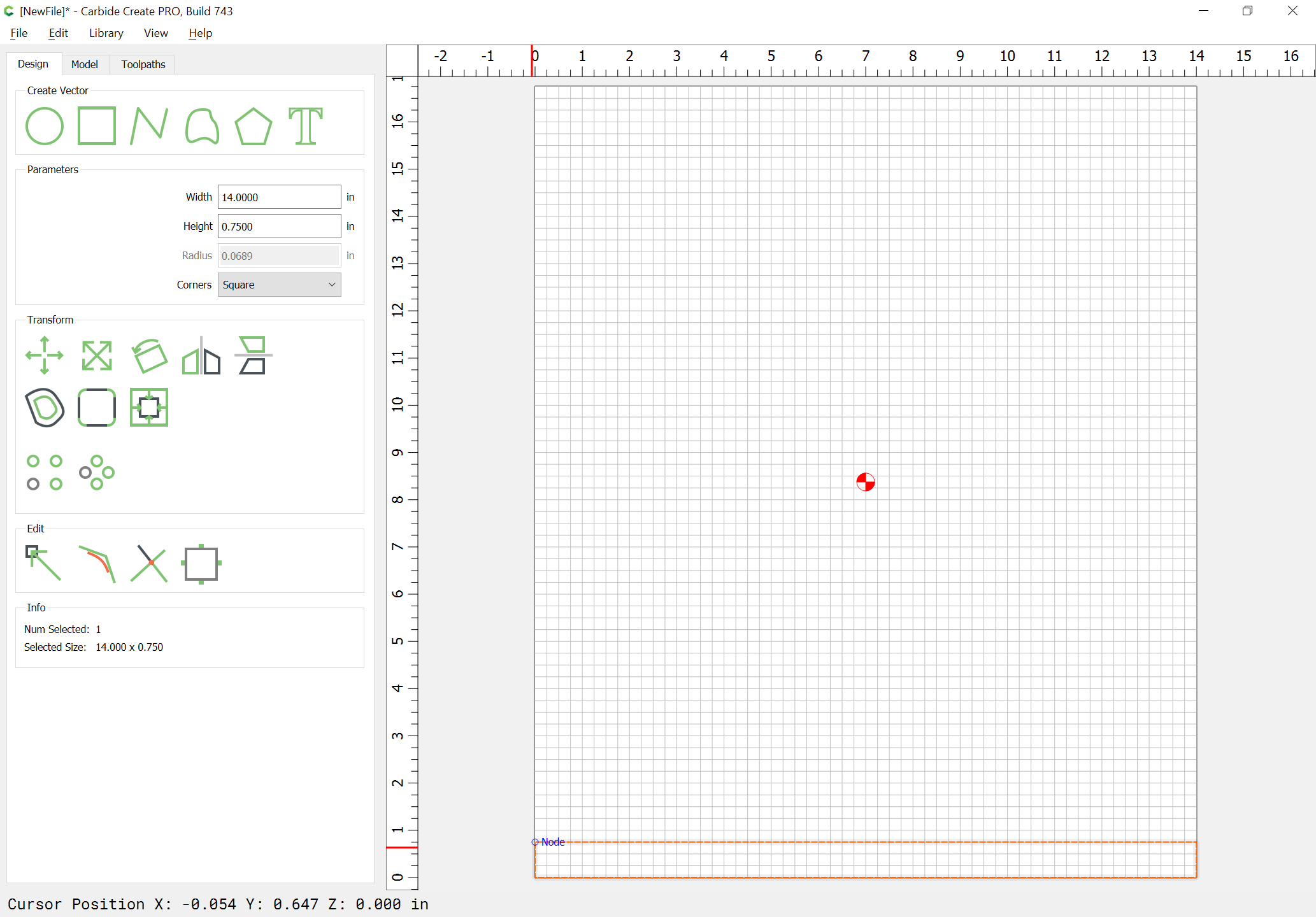
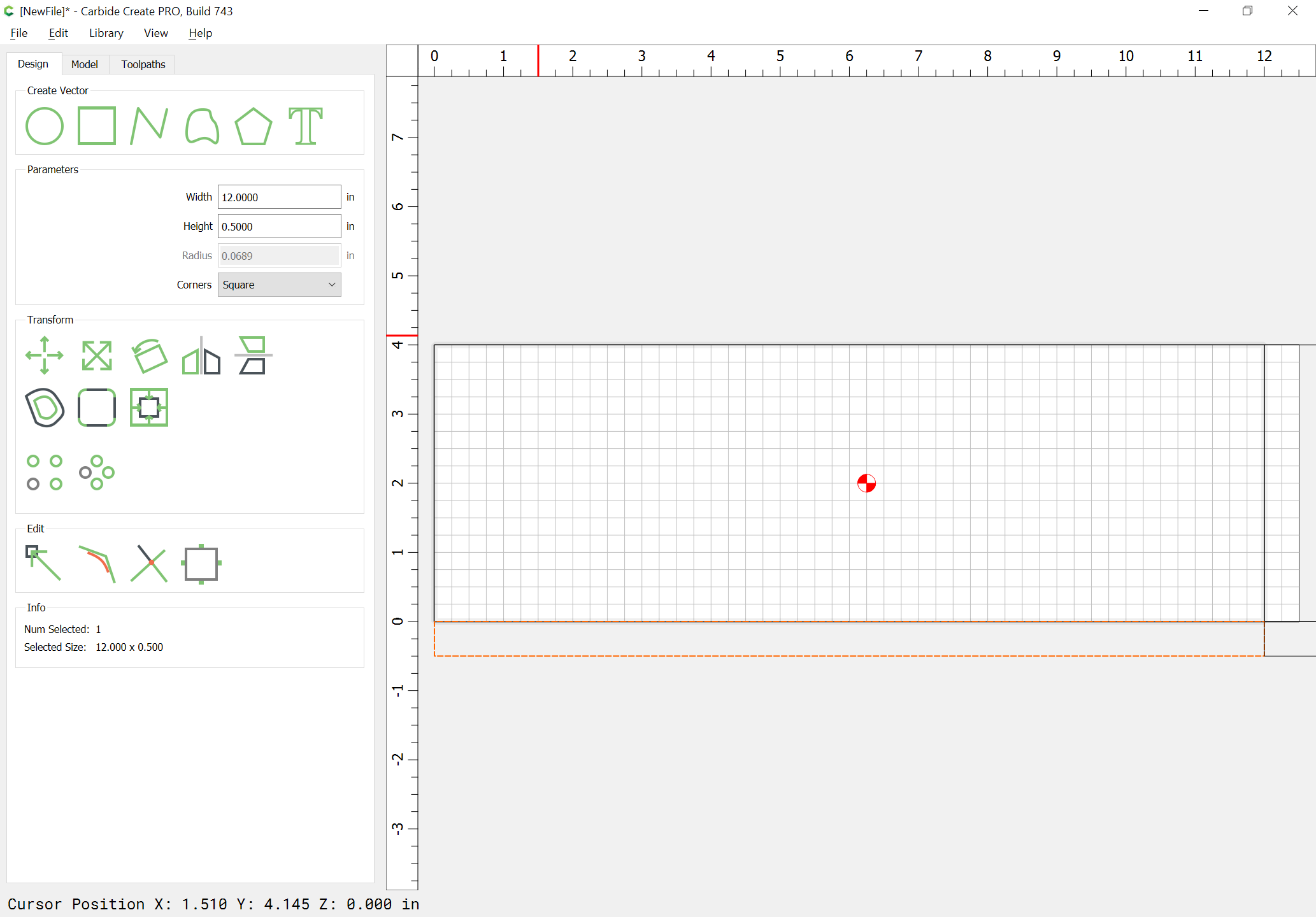
As always, we start by drawing things up in profile:
Then we explode things out to lay the boards flat:
Note that there are two options for the Drawer Face — it can either be a separate part mechanically fastened/glued, or it can be an integral part of the structure — the former should be obvious, so we will investigate the latter here.
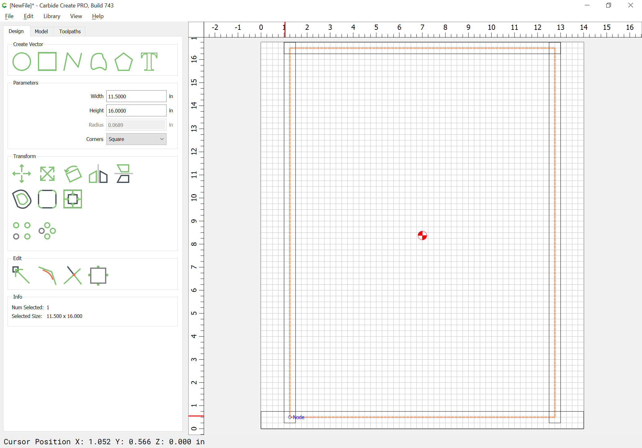
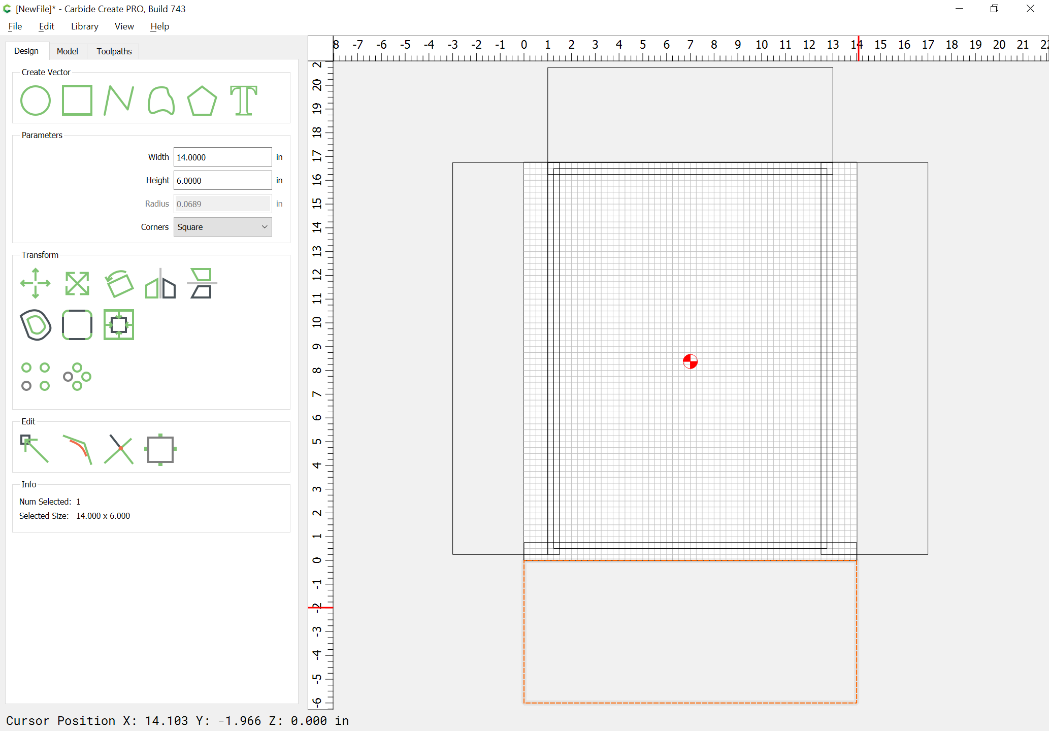
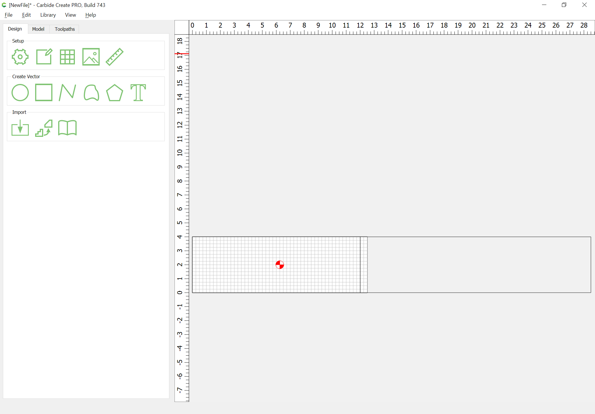
Lay out a pair of boards:
sizing the Stock area so that we can focus on just the joinery.
Again, draw in the profile of the joint:
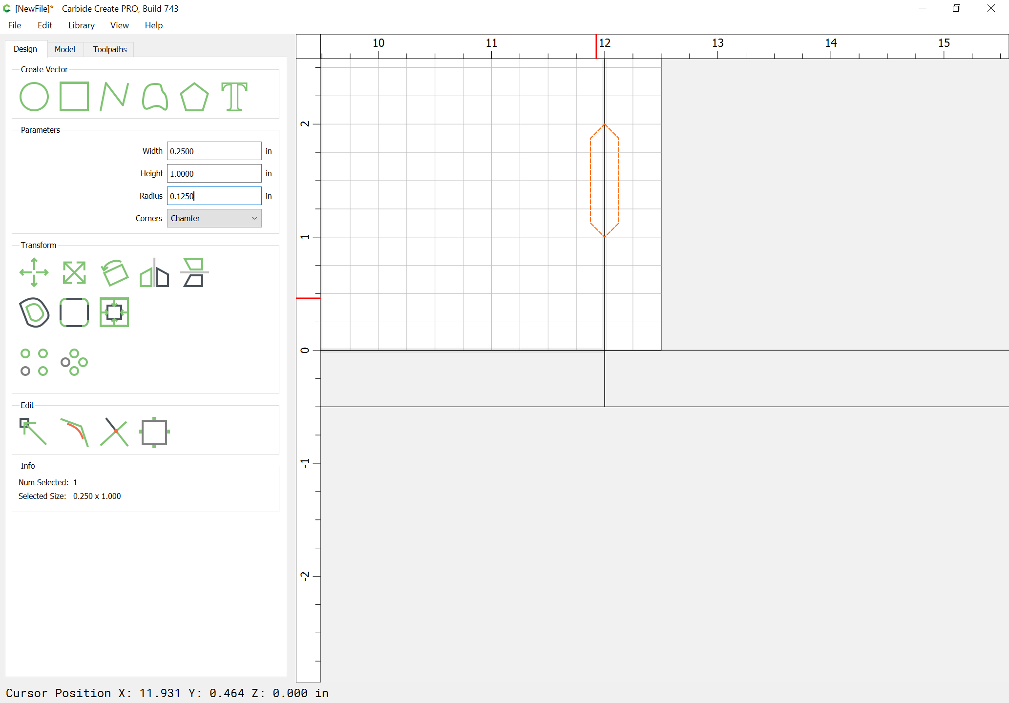
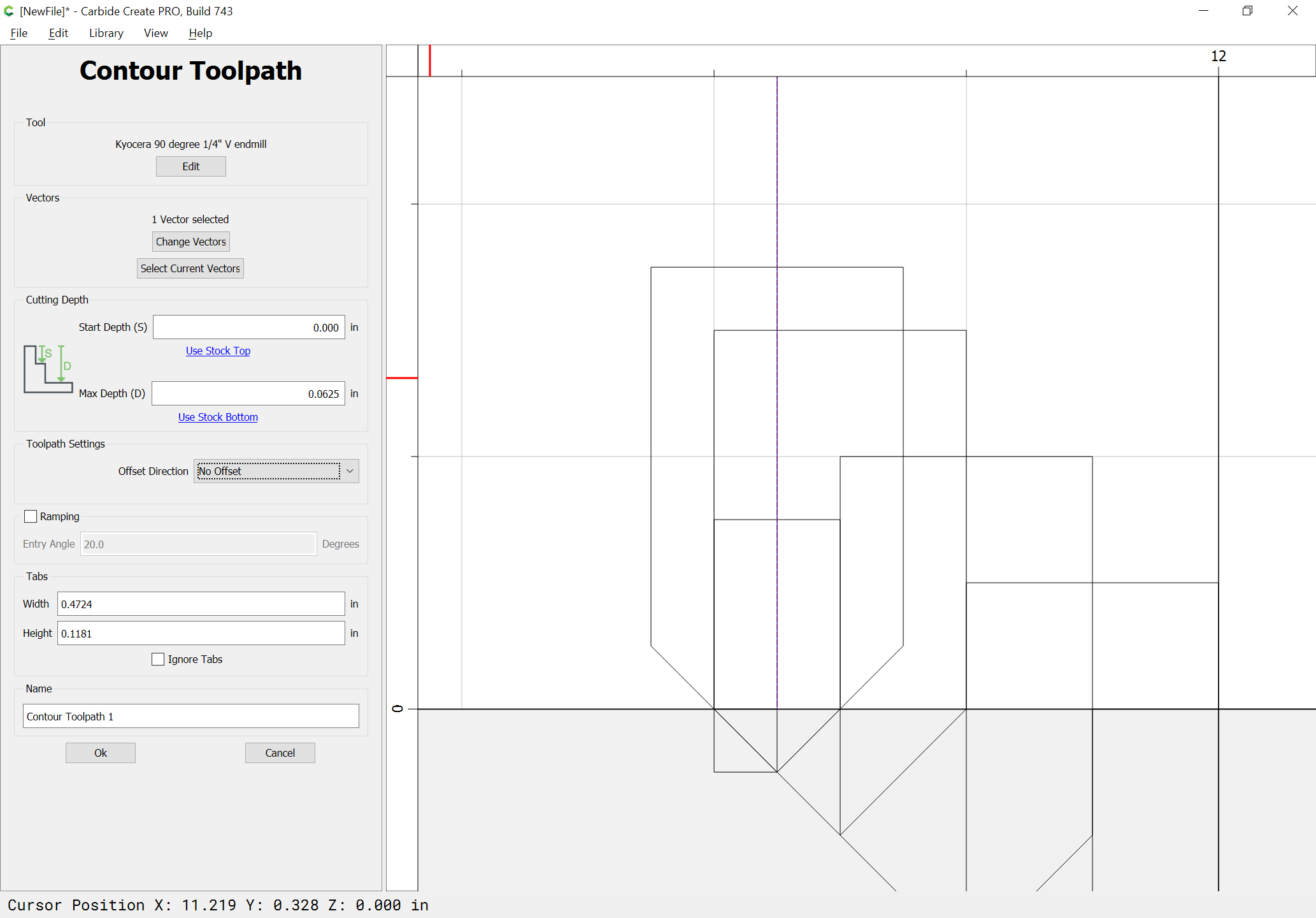
and draw in the V endmill which will be used — this needs to be significantly narrower than the stock thickness — we will use a 1/4" 90 degree V endmill:
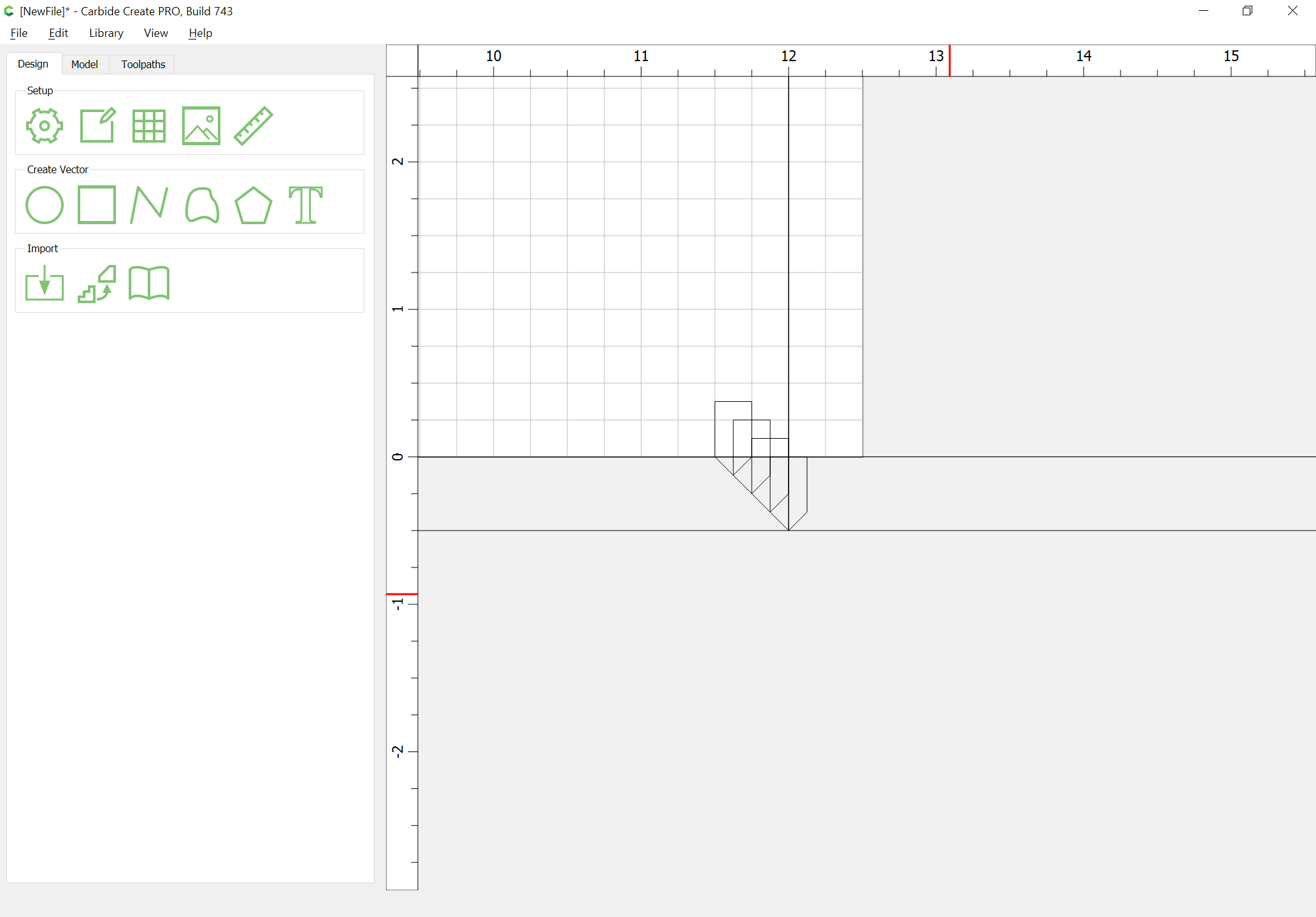
Duplicating the V endmills, we can see how multiple cuts w/ the V endmill will be necessary to cut the V chamfer at the top/bottom of the boards:
Trying something a bit different here, we will have the initial cut with the V endmill be only 1/2 its height:
(this should simplify the toolpaths, and get us a bit more surface area for the joint)
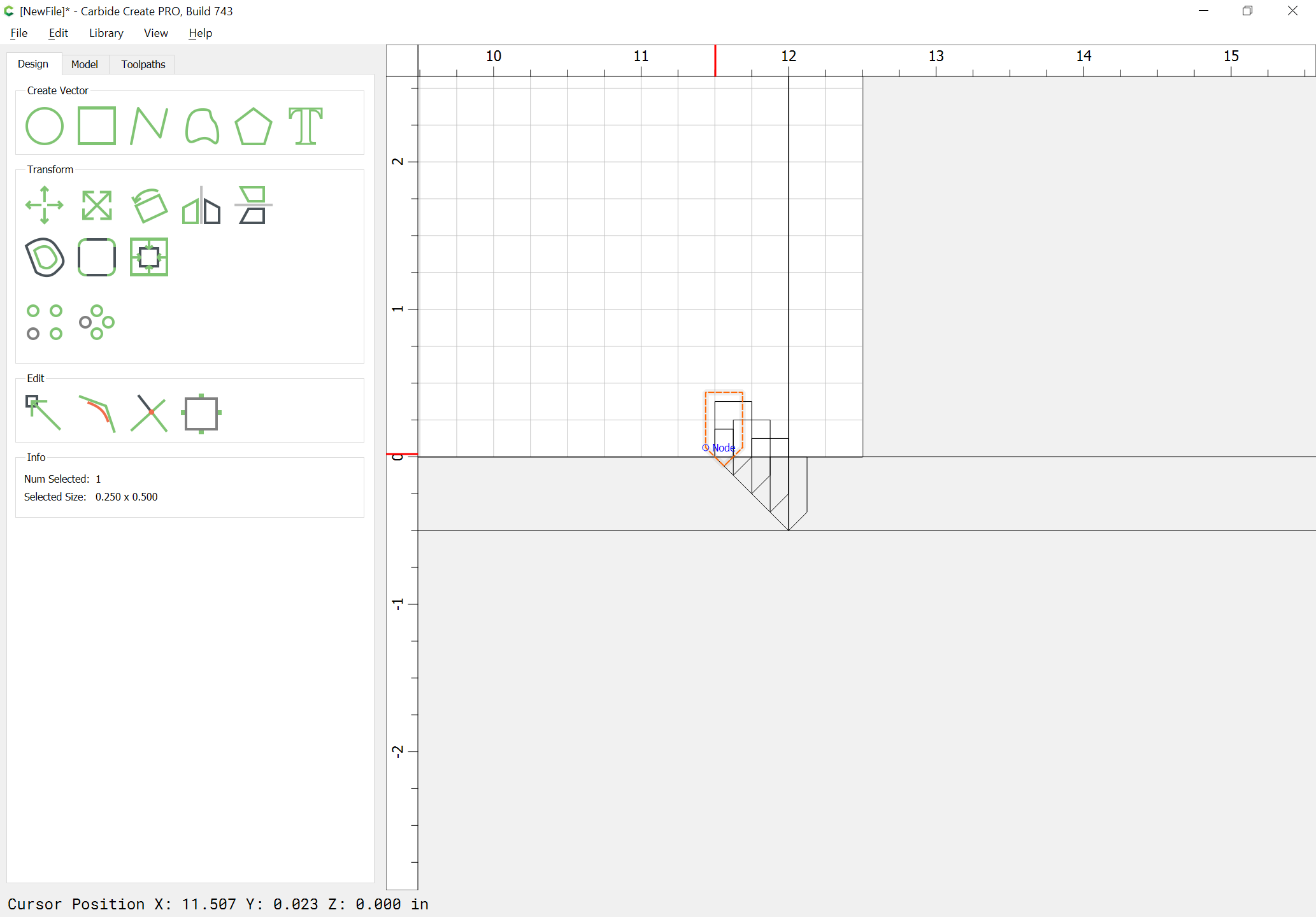
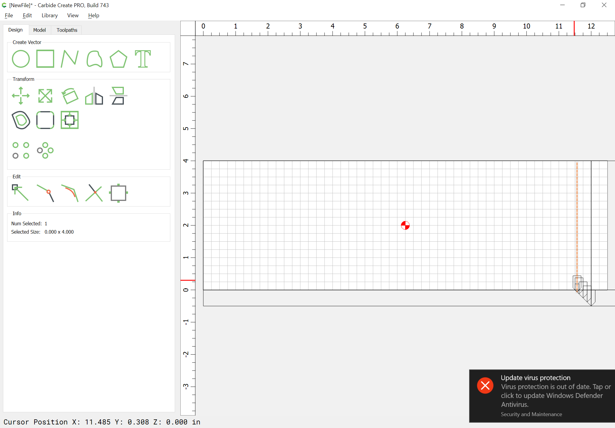
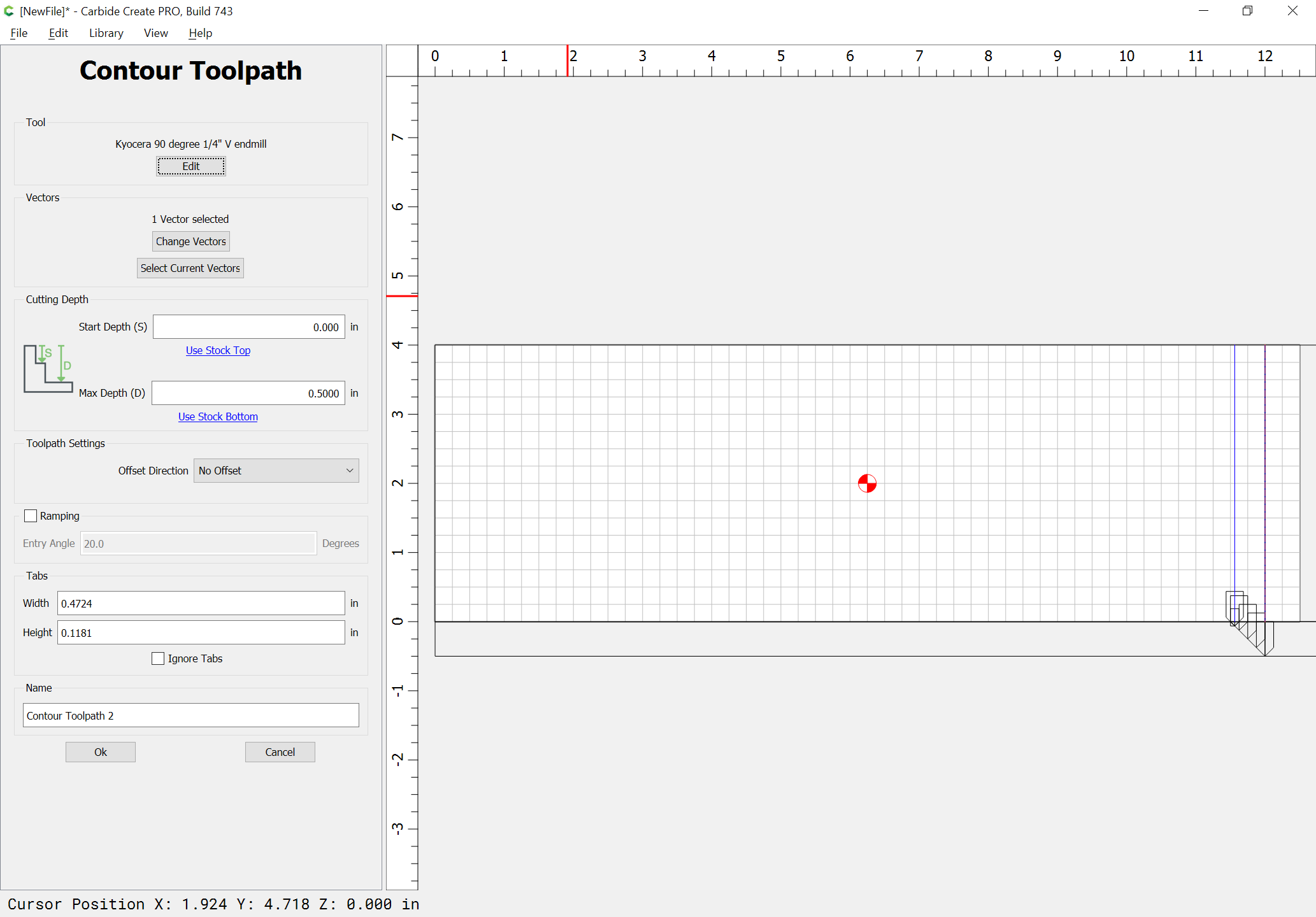
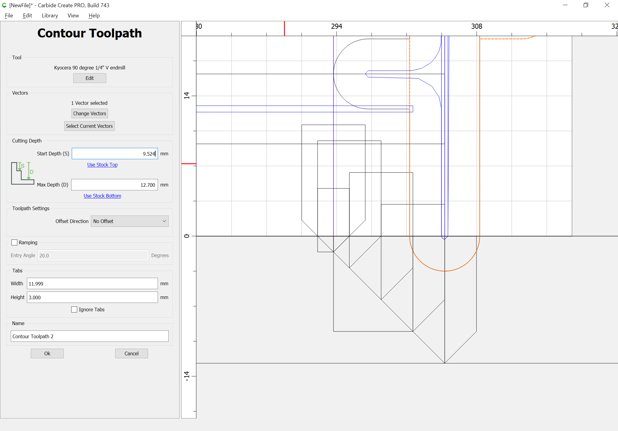
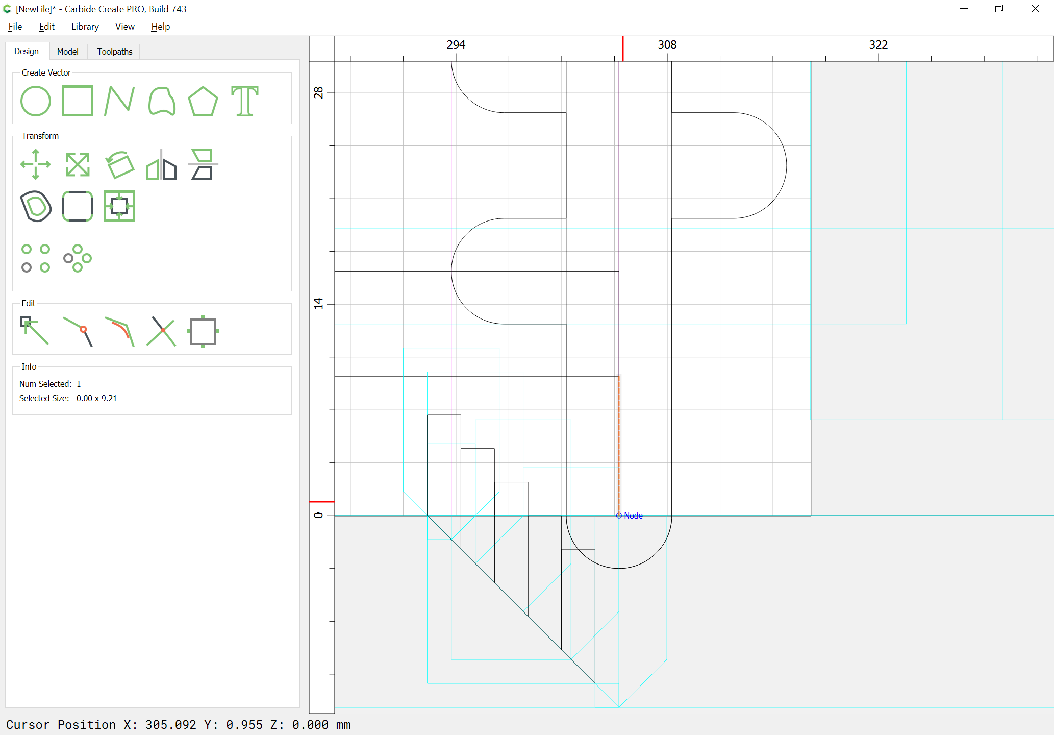
Draw in a line as tall as the boards and position it at the tip of the uppermost V endmill proxy:
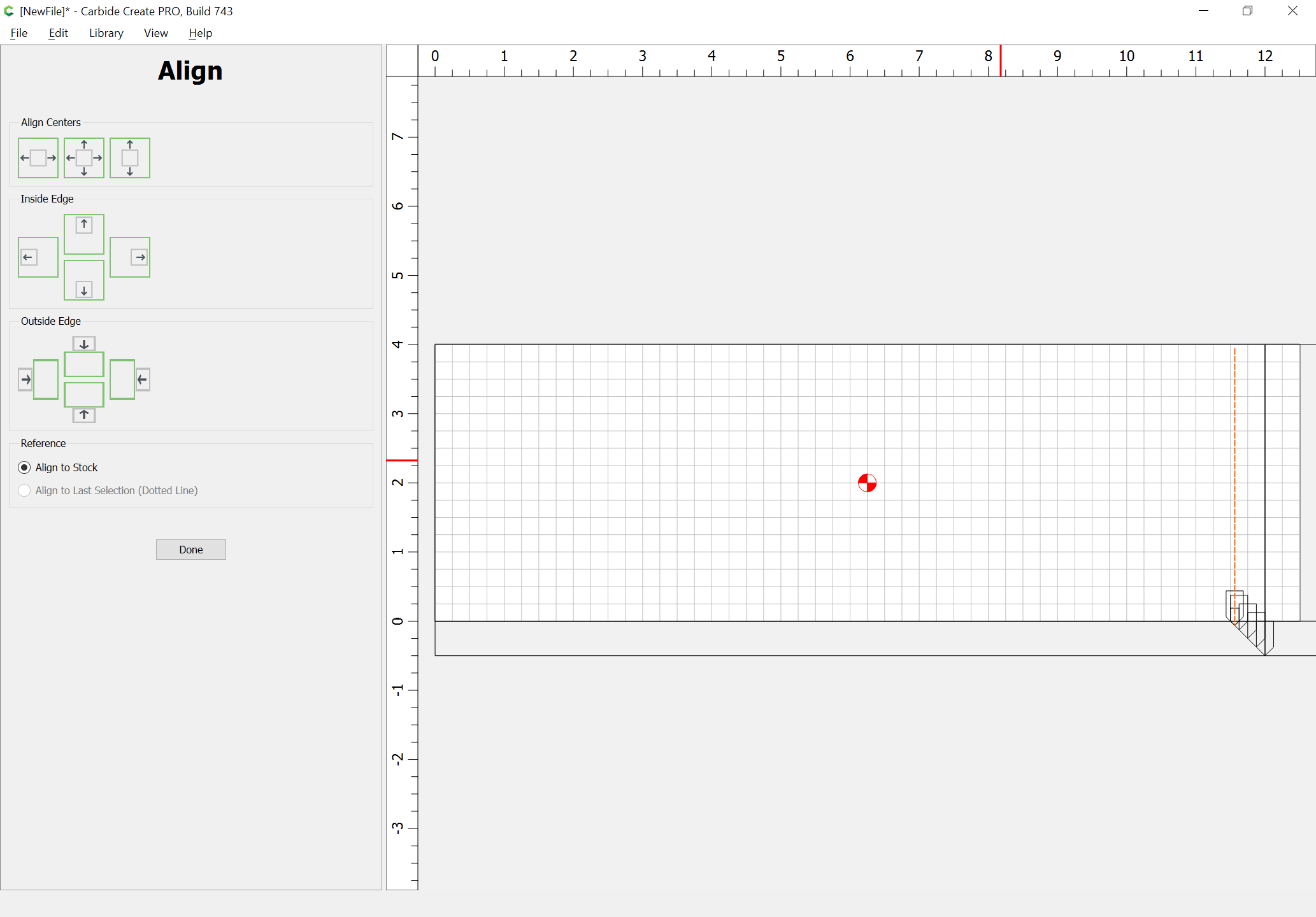
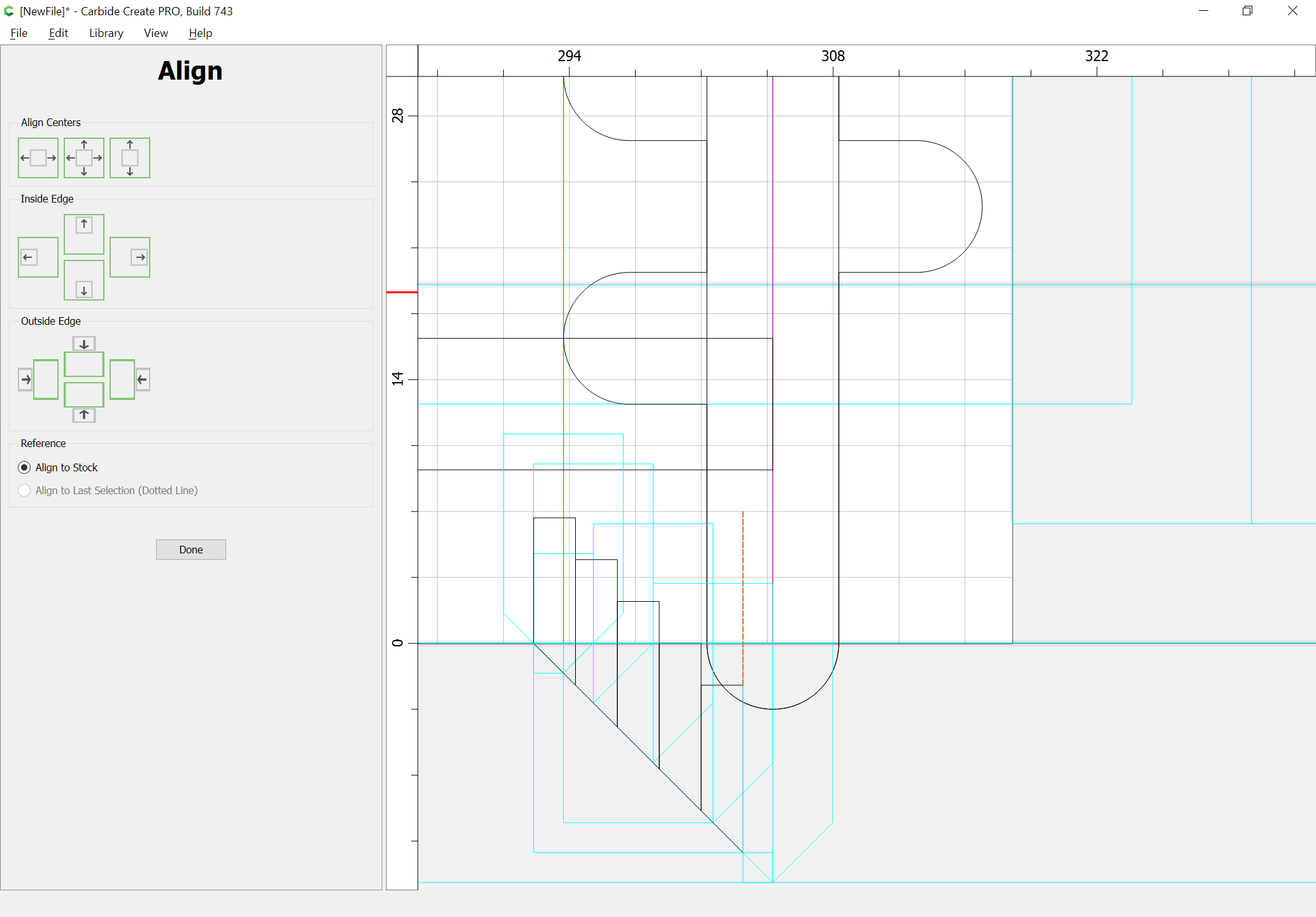
Align it against the stock:
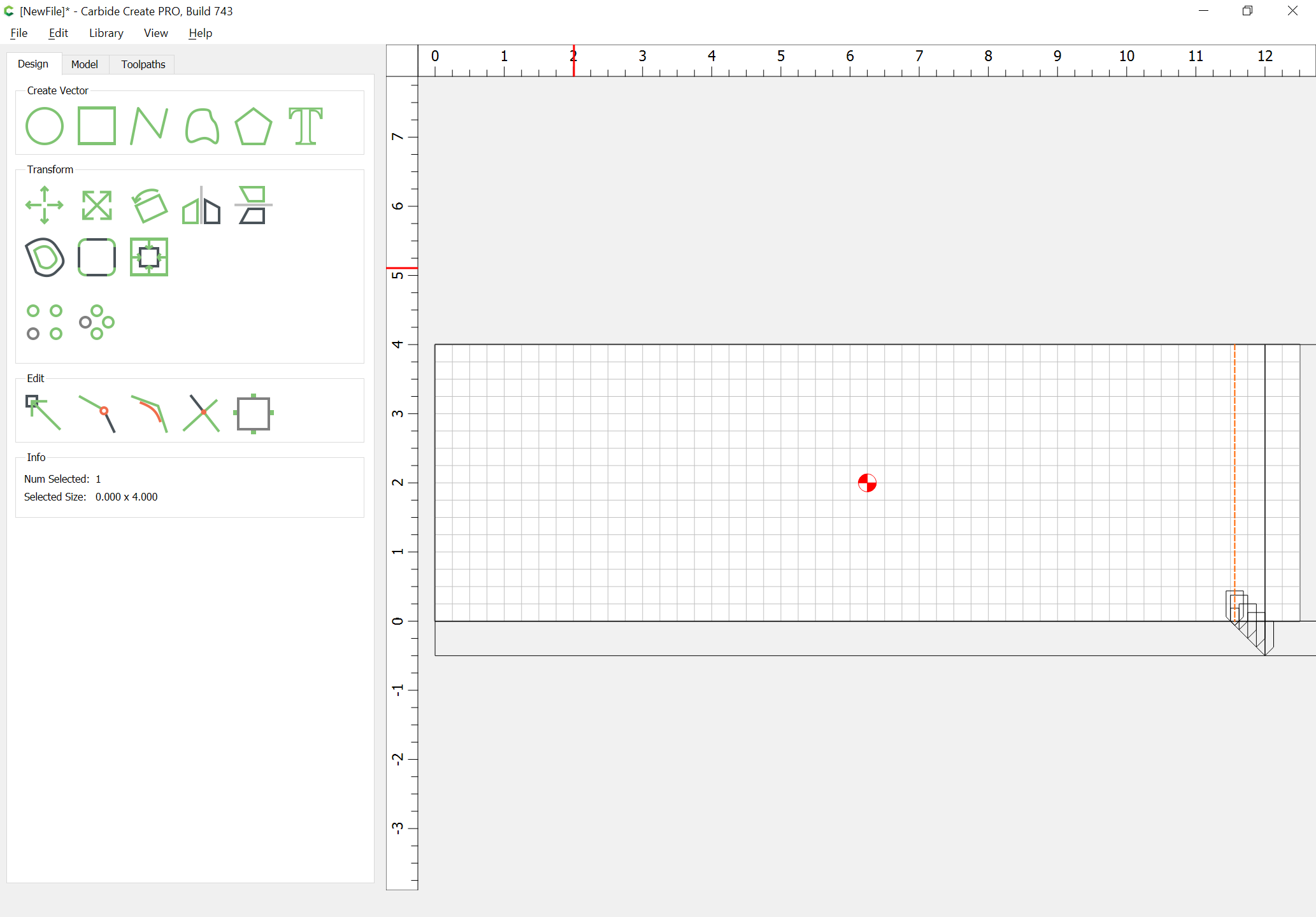
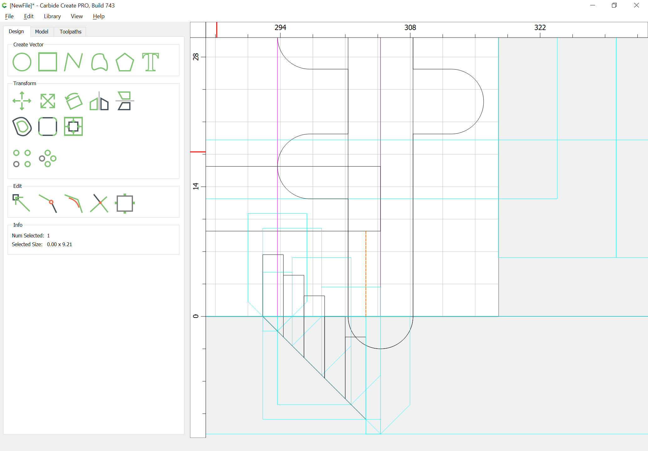
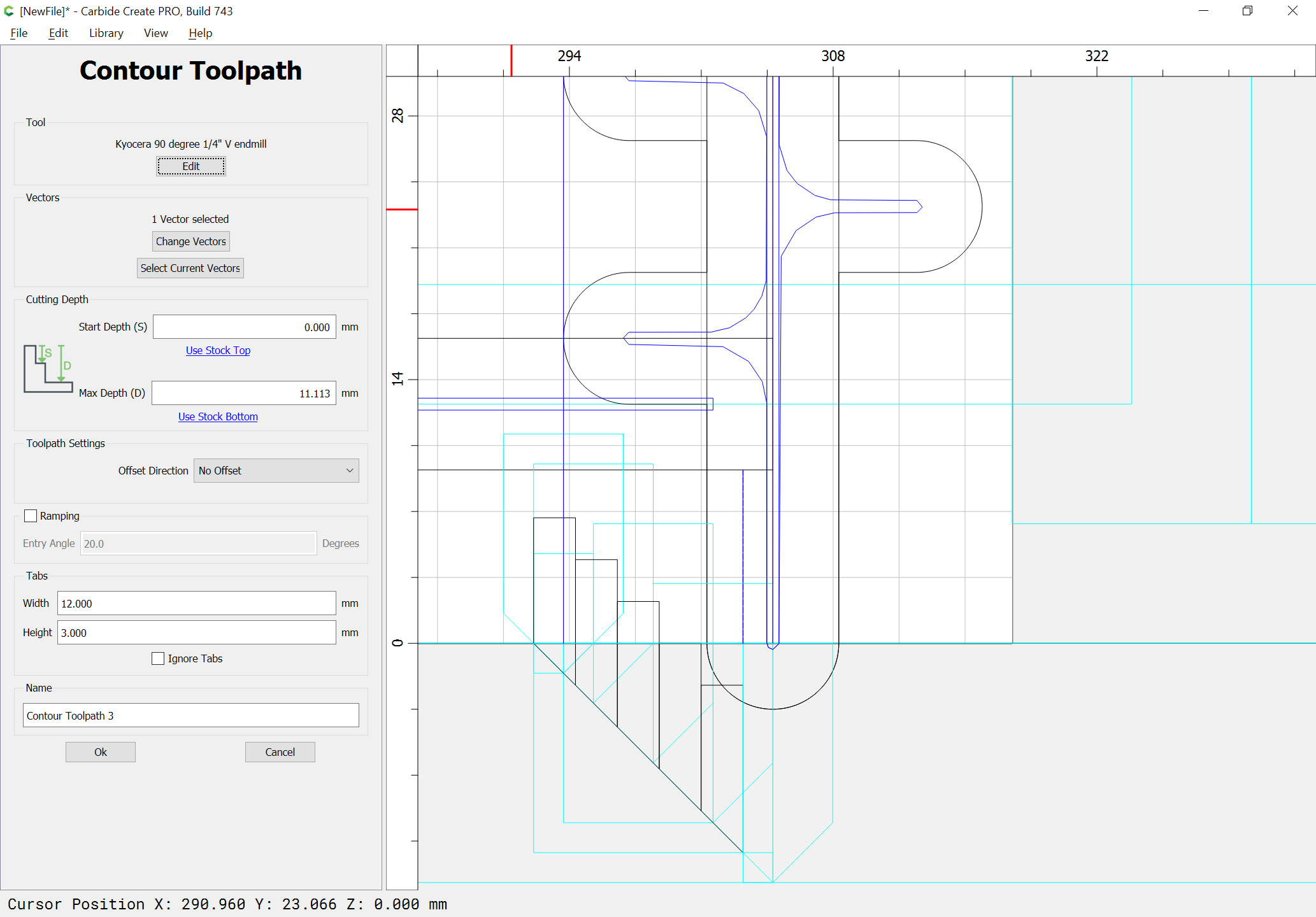
Assign it to have a no offset contour as deep as:
Create another line along the two boards and assign it a no offset contour at the stock bottom:
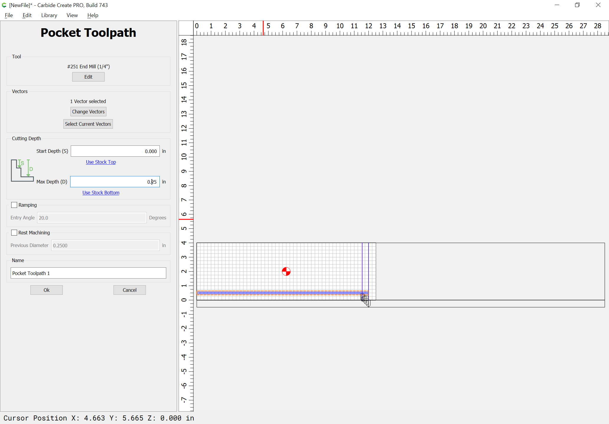
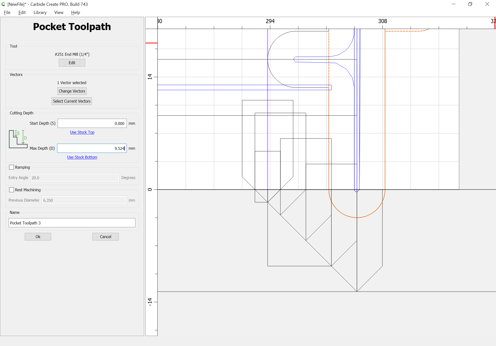
Draw in the geometry for the rabbet for the drawer bottom:
and assign it a pocket toolpath to the desired depth:
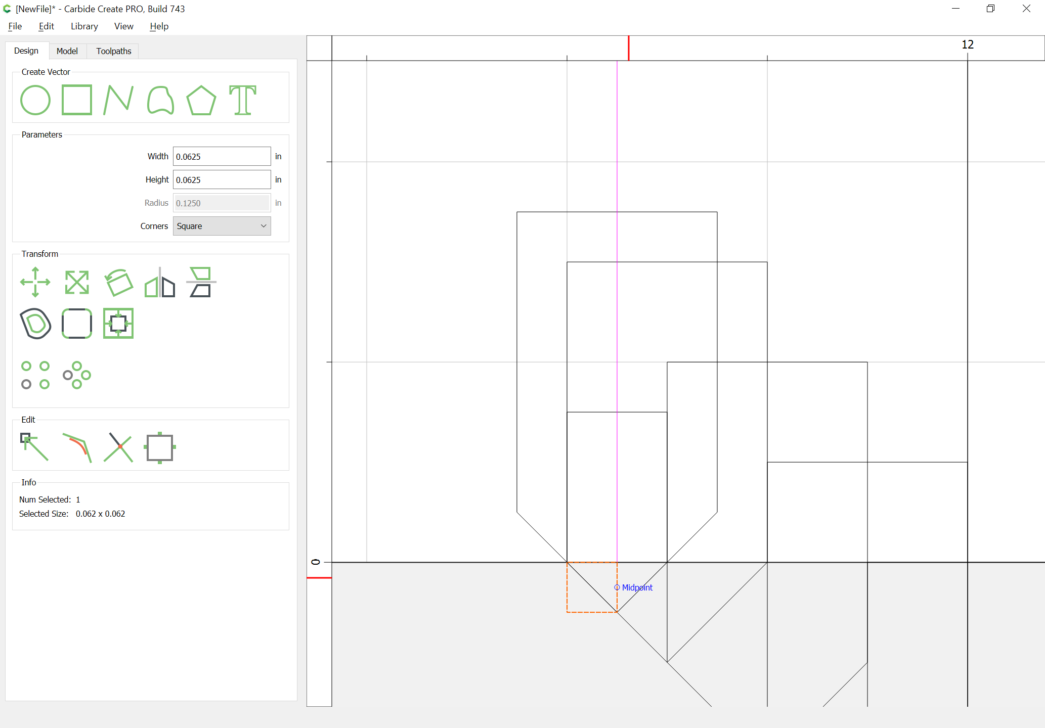
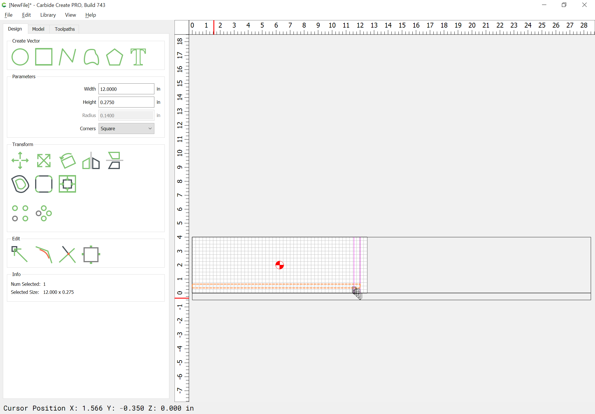
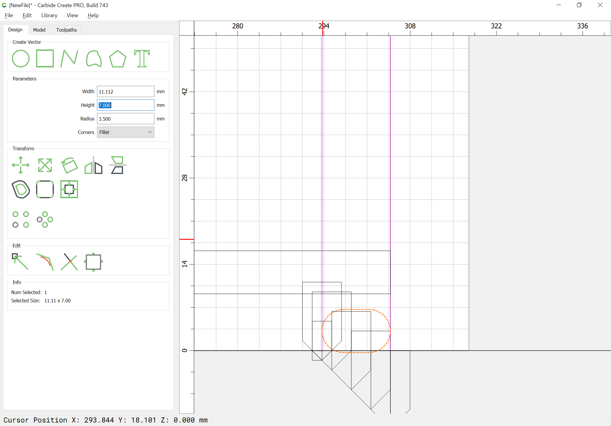
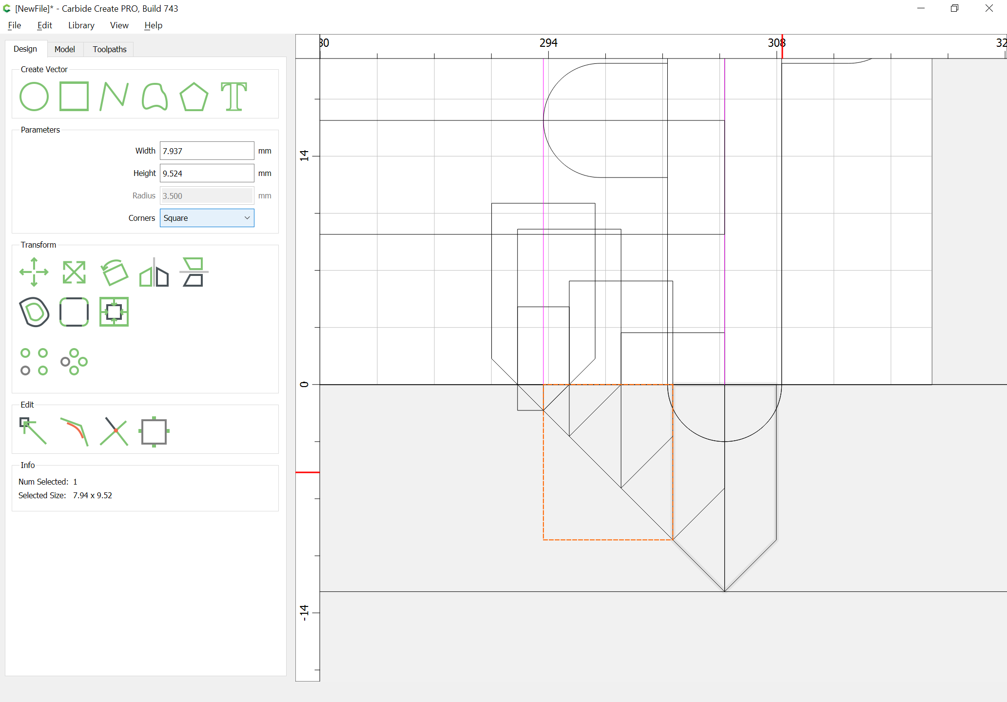
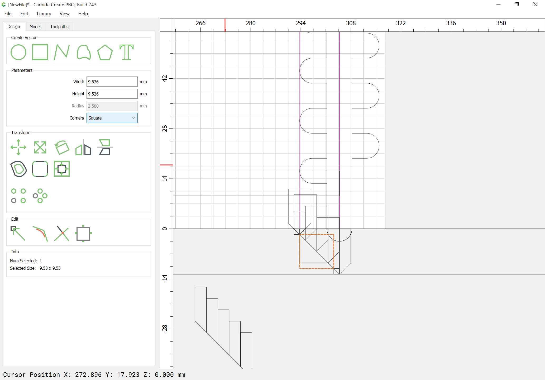
Change the grid spacing to be an integral of the joinery — we will switch to metric and use 7mm, so 3.5mm — draw a rectangle which reaches from the end of the board to the upper V contour and is the desired height:
Position it centered at the upper right corner of the rabbet:
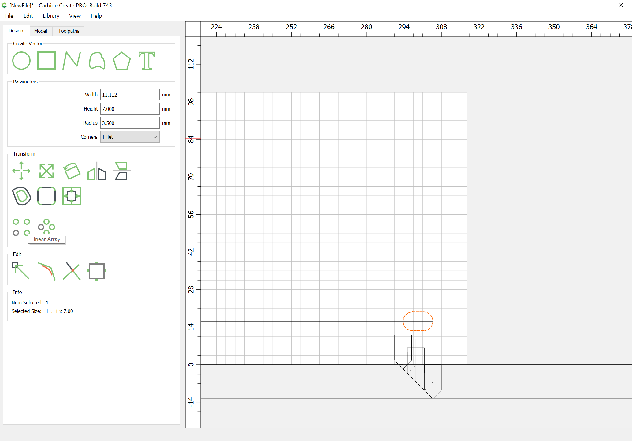
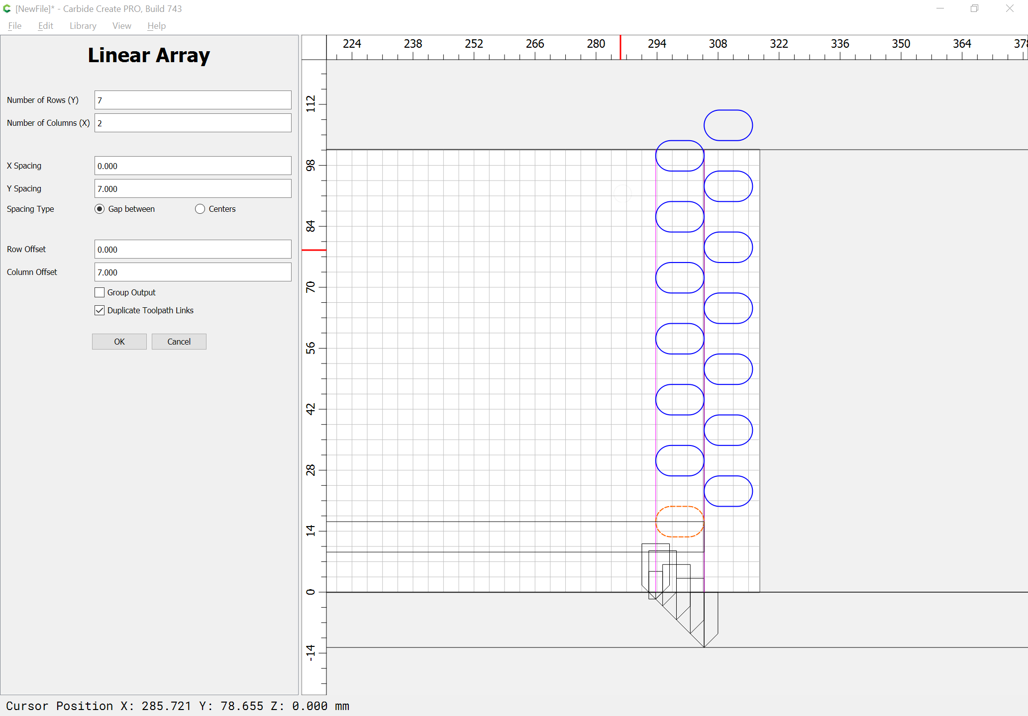
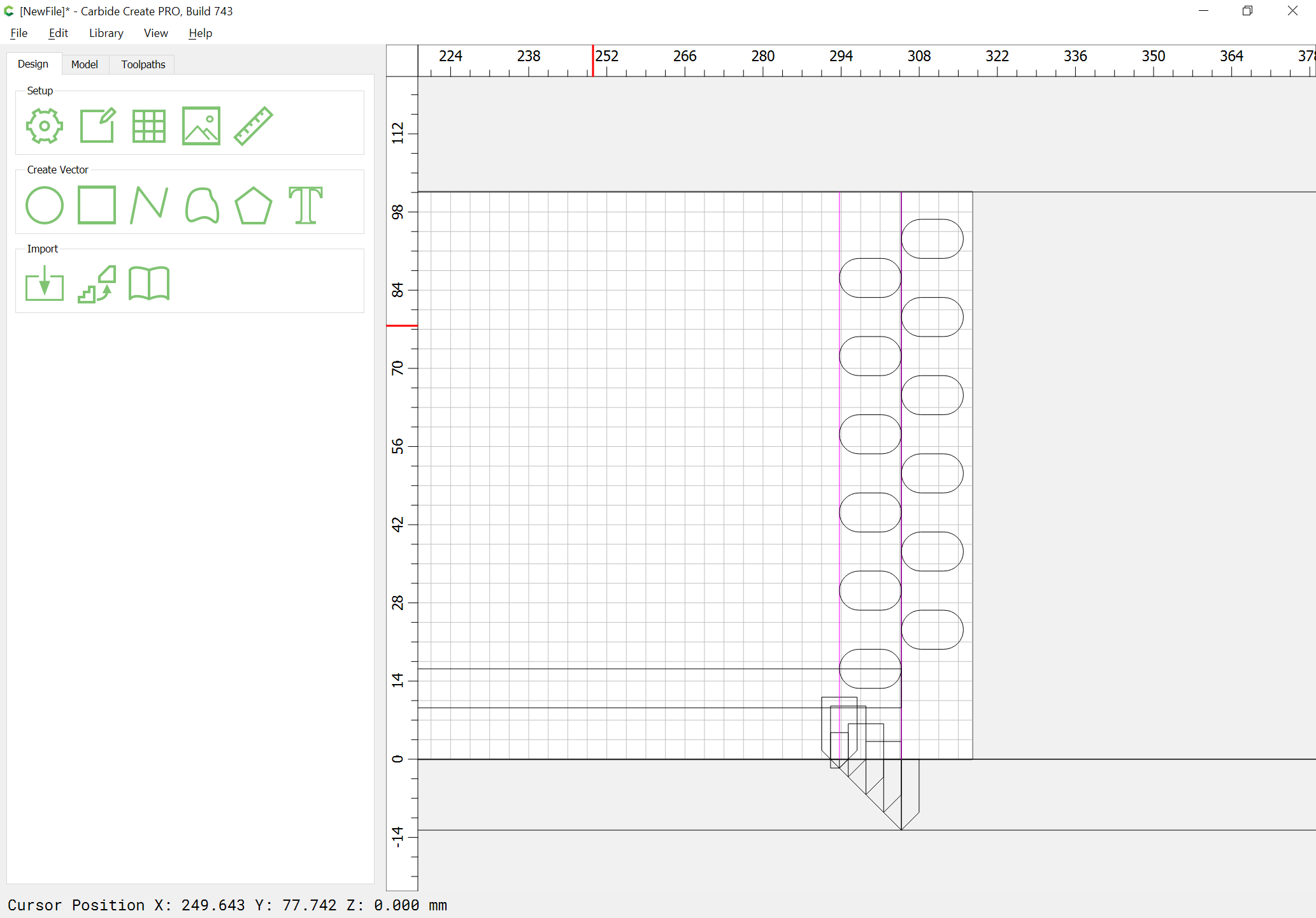
and use the Linear Array tool to make duplicates of it which define the joinery and extend beyond the top of the board:
OK
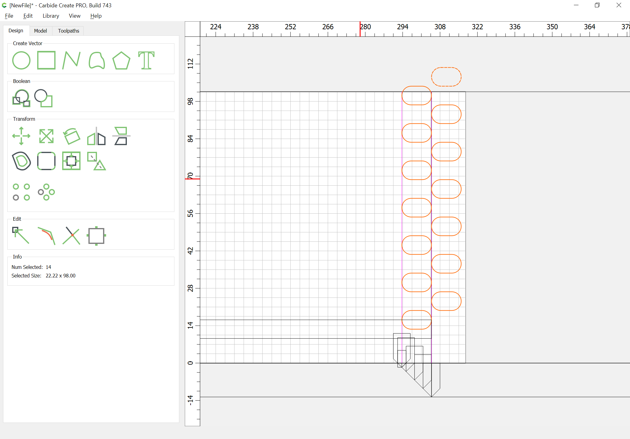
Delete the elements which extend too far:
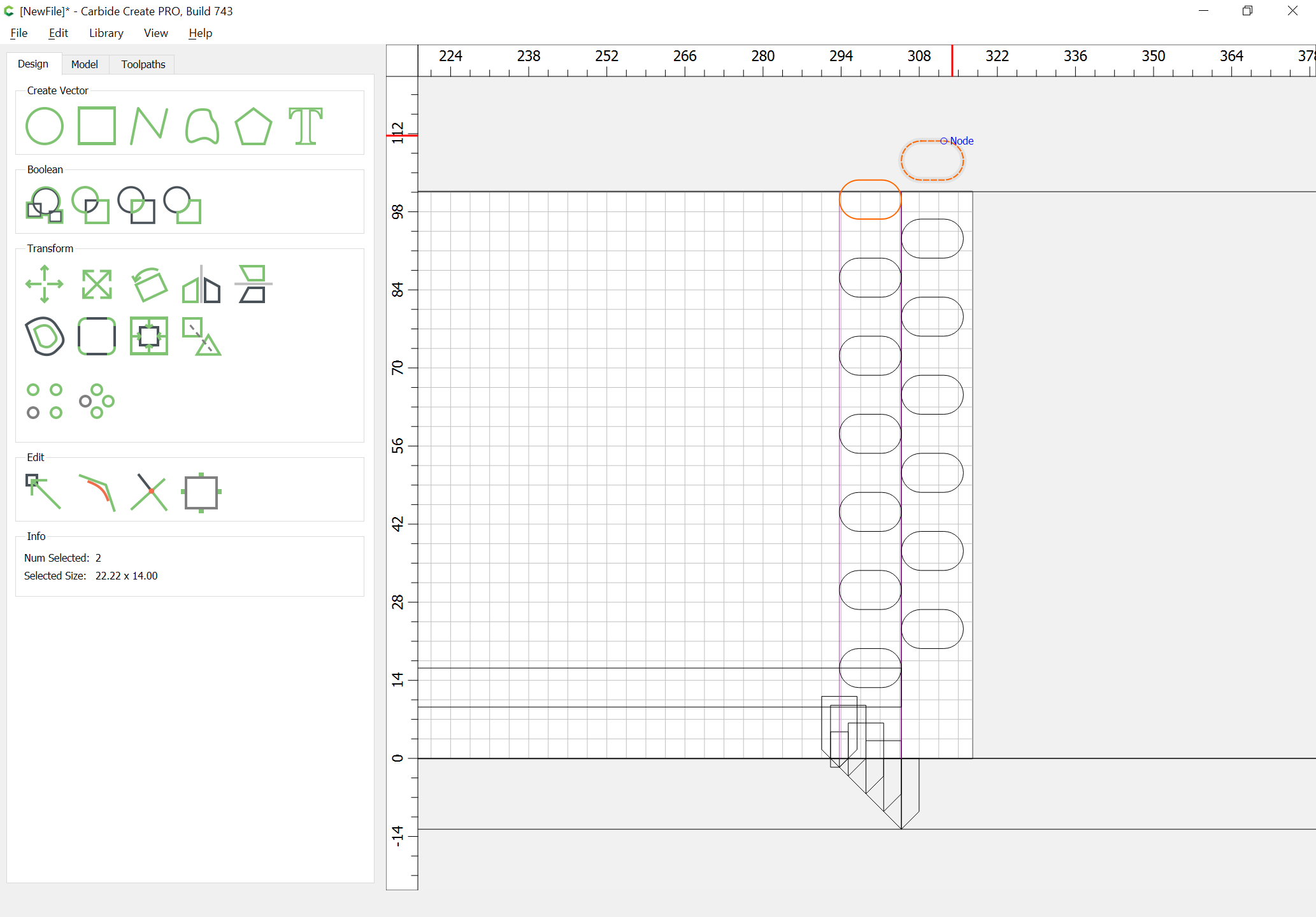
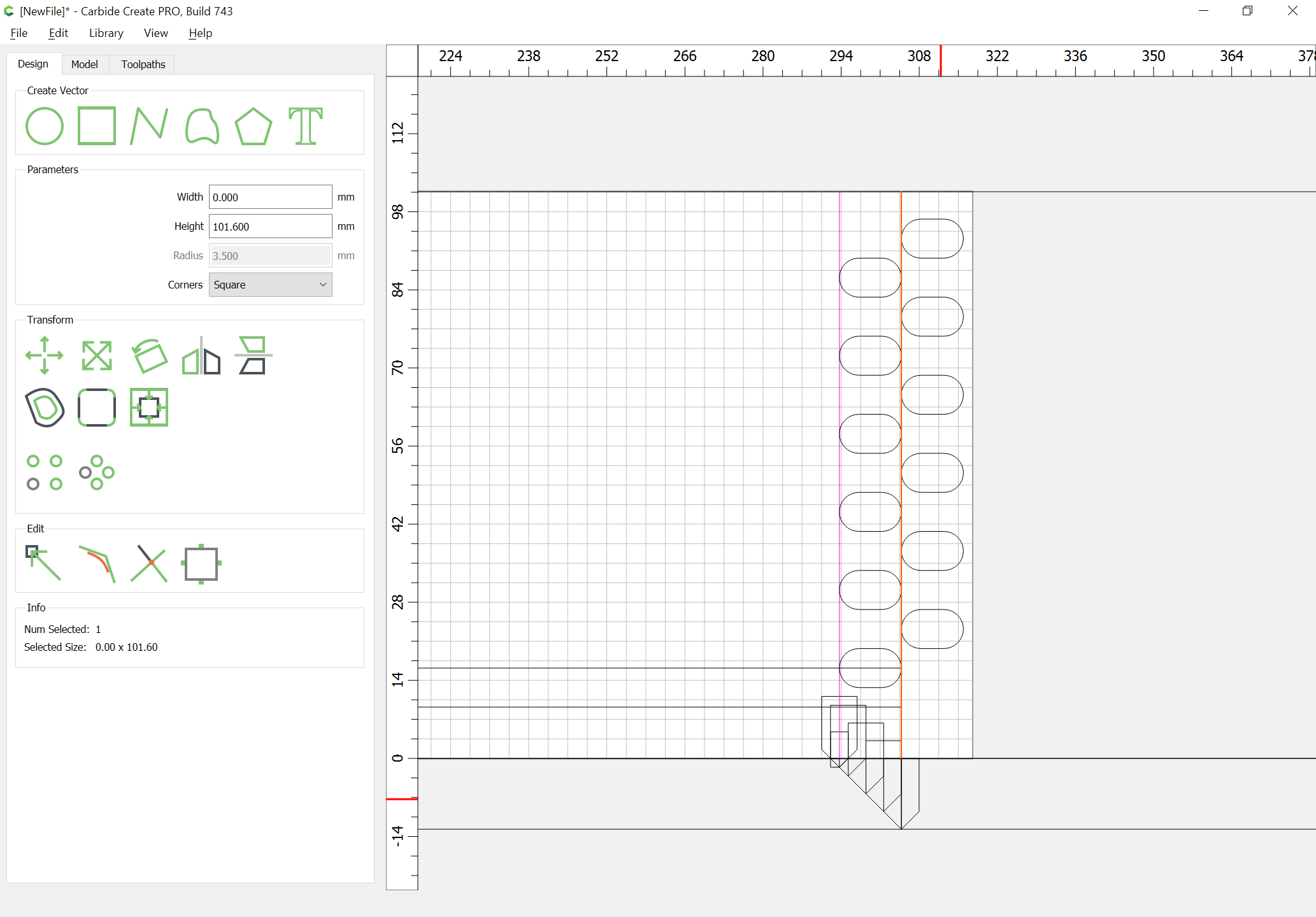
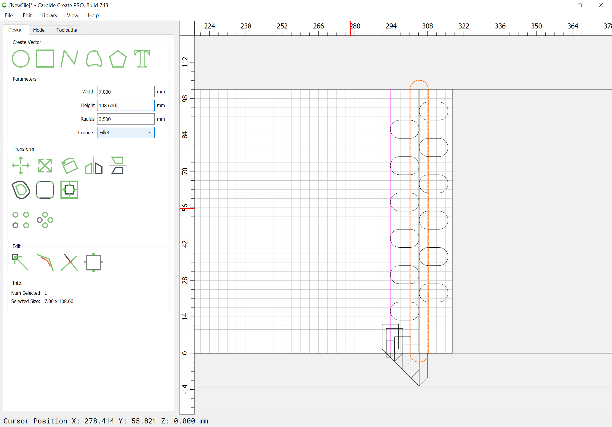
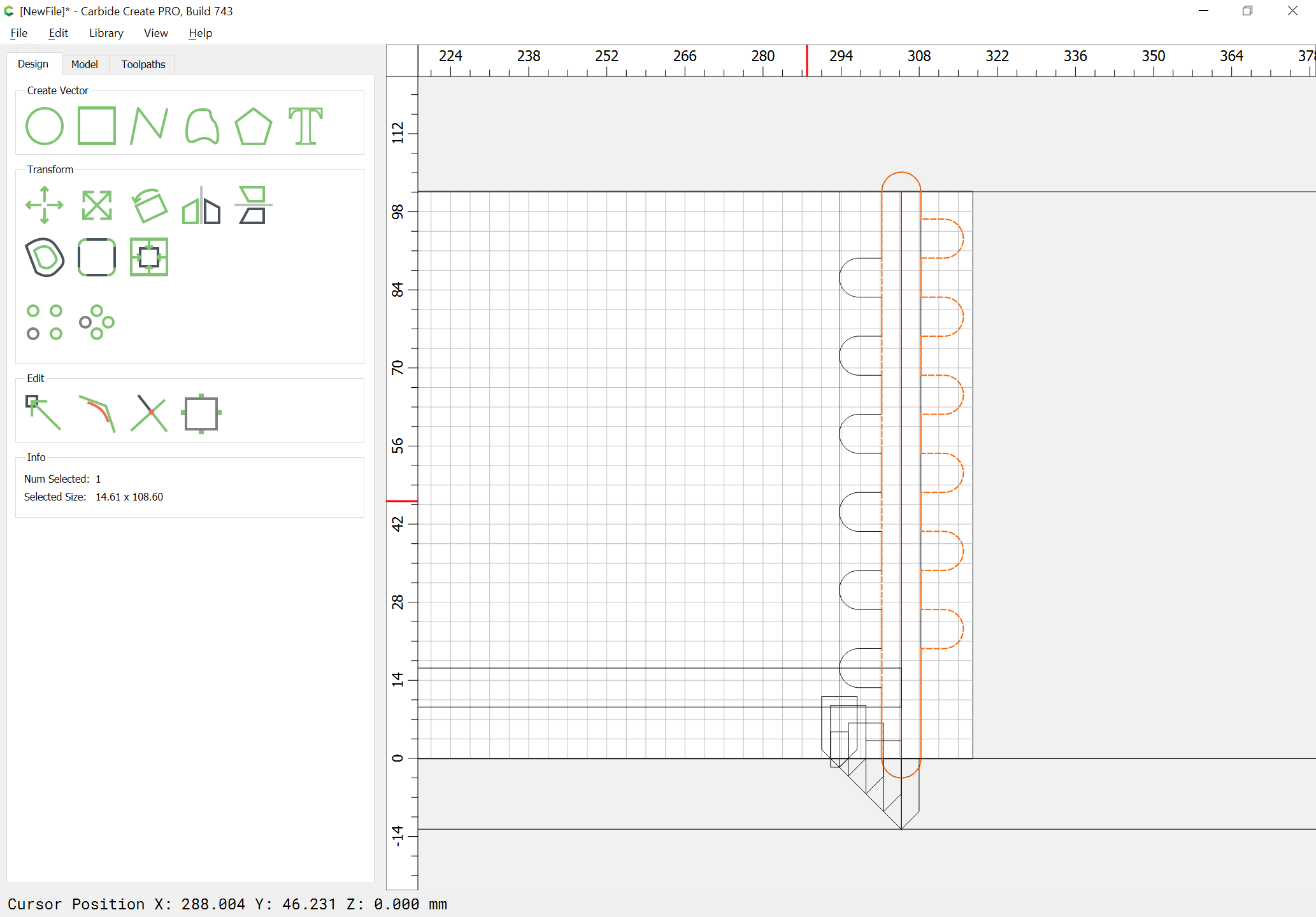
Draw in a zero width rectangle which extends from the top to the bottom of the line in-between the two boards:
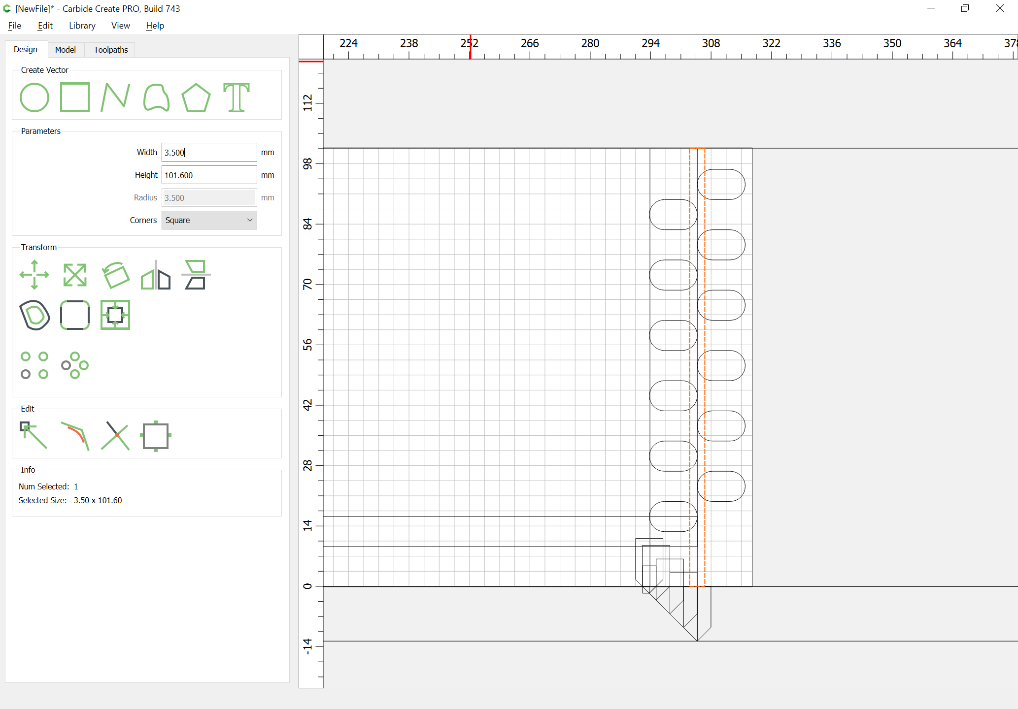
Set it to be the same width as the height of the rectangles used for the joinery:
and add that dimension to the height, and round the ends:
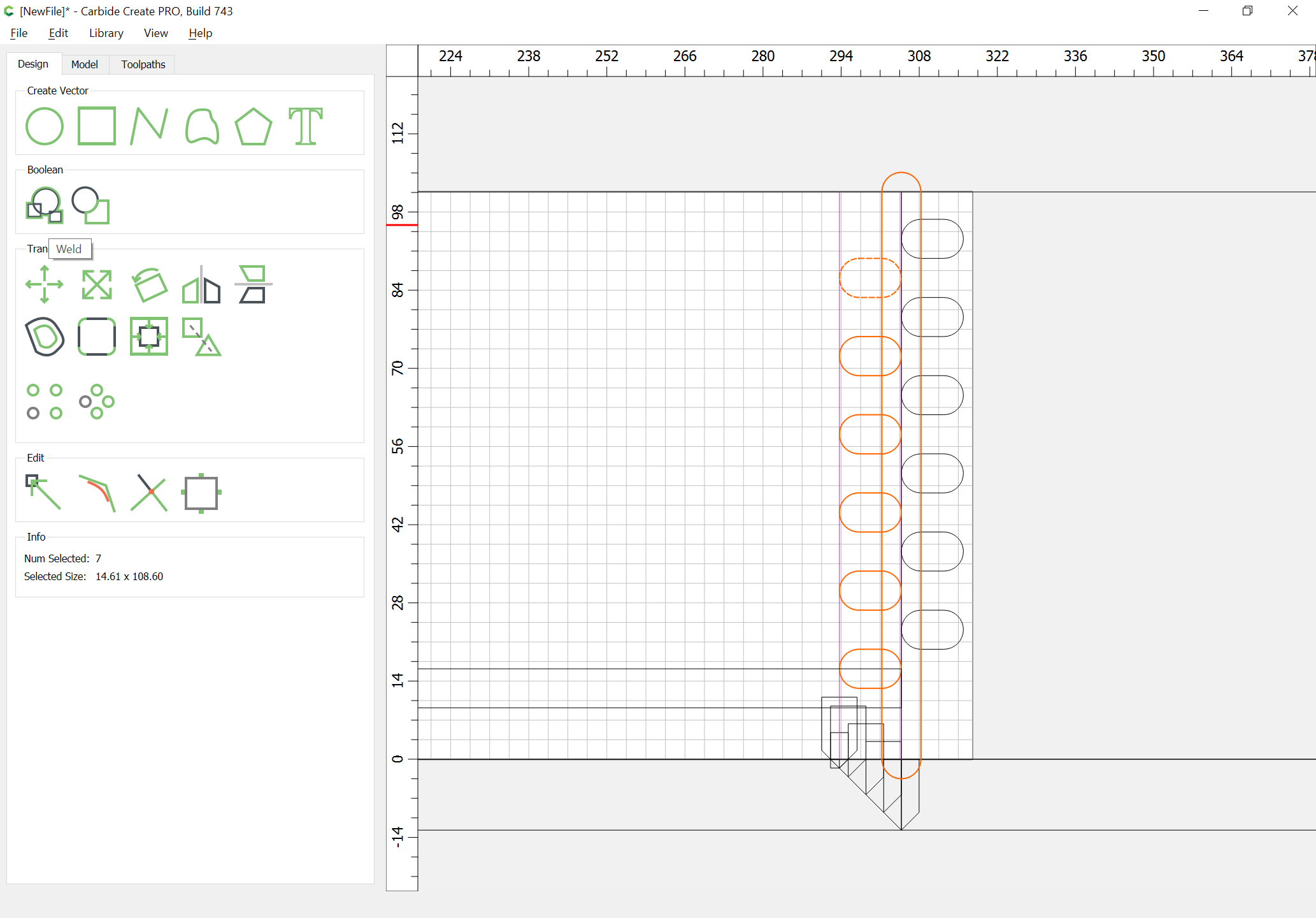
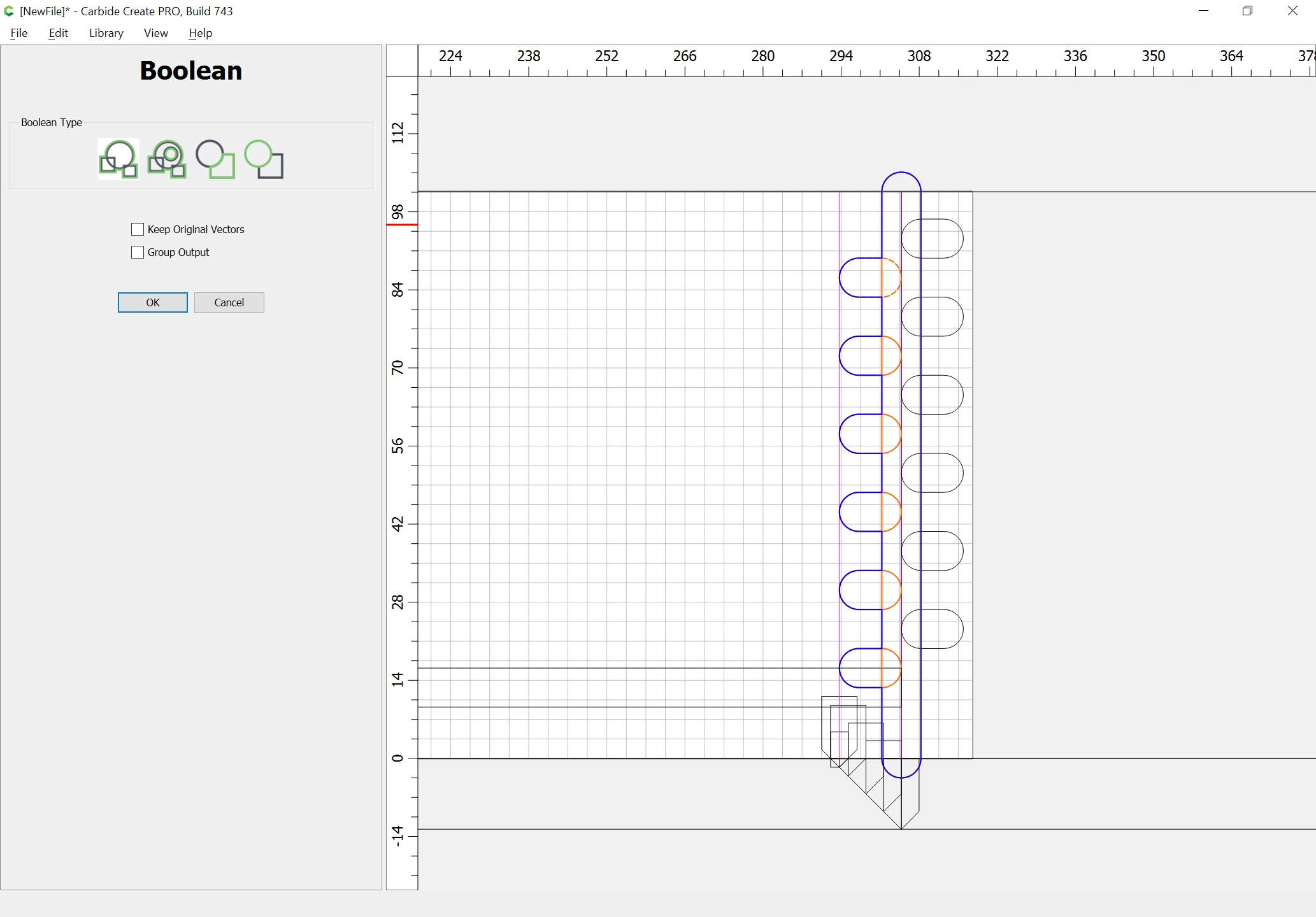
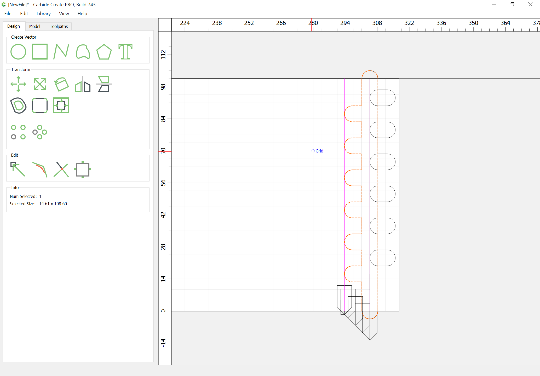
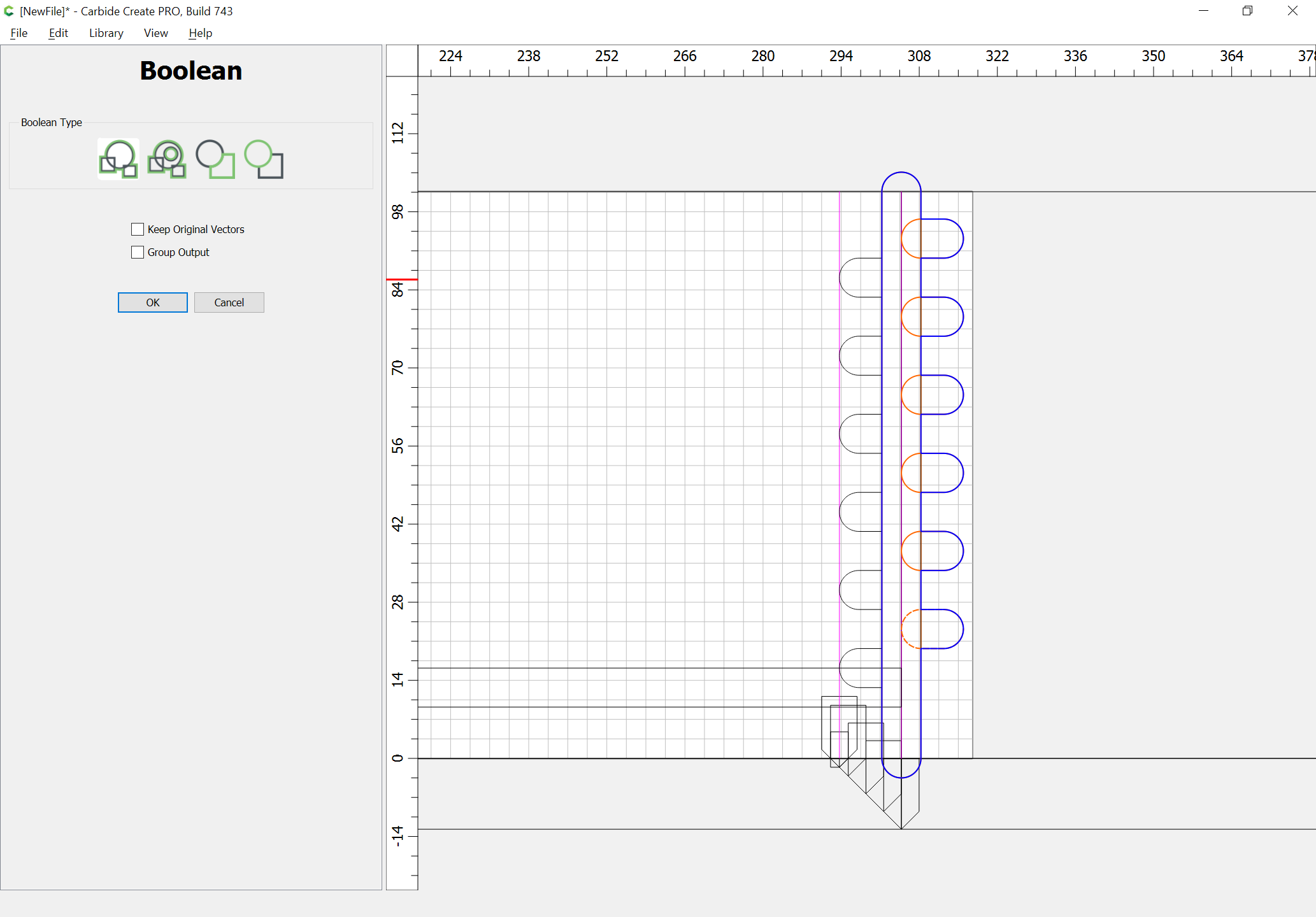
Duplicate this in place and Boolean Union (or use Trim Vectors) to combine each copy w/ one set of the joinery geometry:
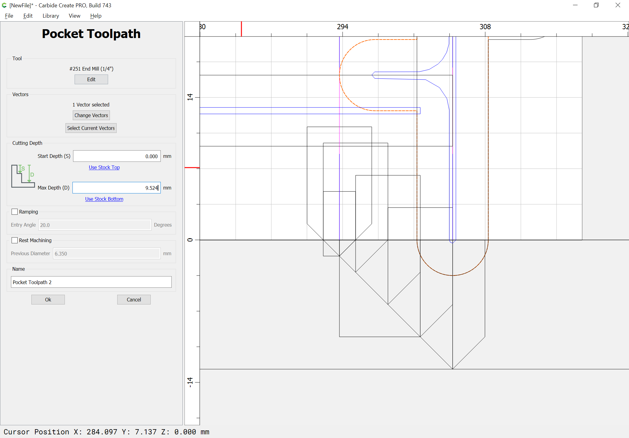
Assign a toolpath to each which cuts as deeply as is necessary to clear to the bottom of the joint:
and one can adjust the bottom V endmill pass to start at the bottom of that pocket, since the square tooling will be used first, and the V endmill last:
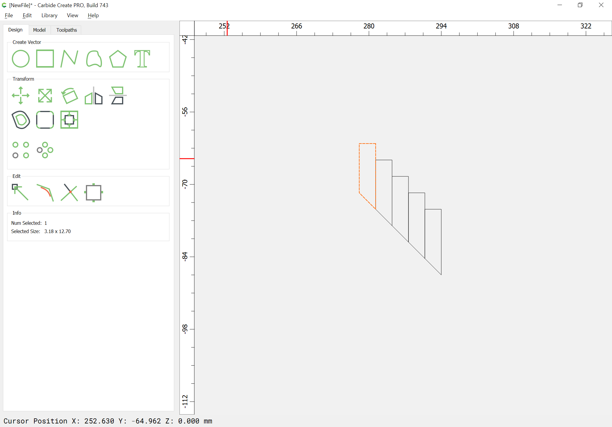
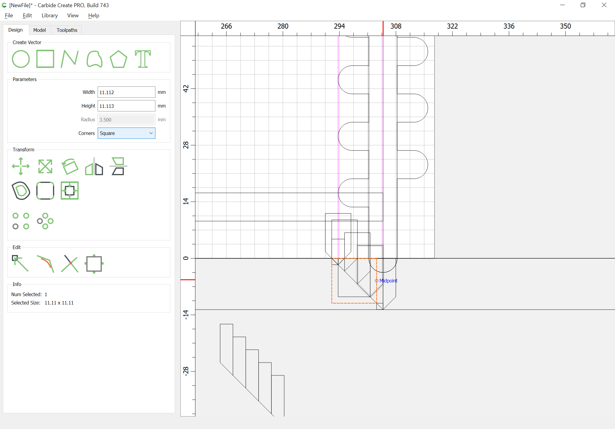
Lastly we determine how to chamfer the top and bottom of the boards:
Halve the tool, and stack up as many duplicates as one wishes to make passes:
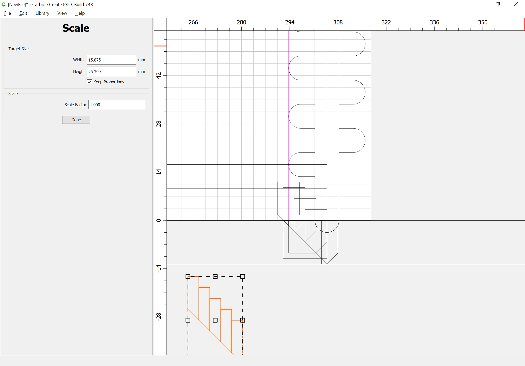
and then draw in a box which measures where one wants the chamfering passes to be made:
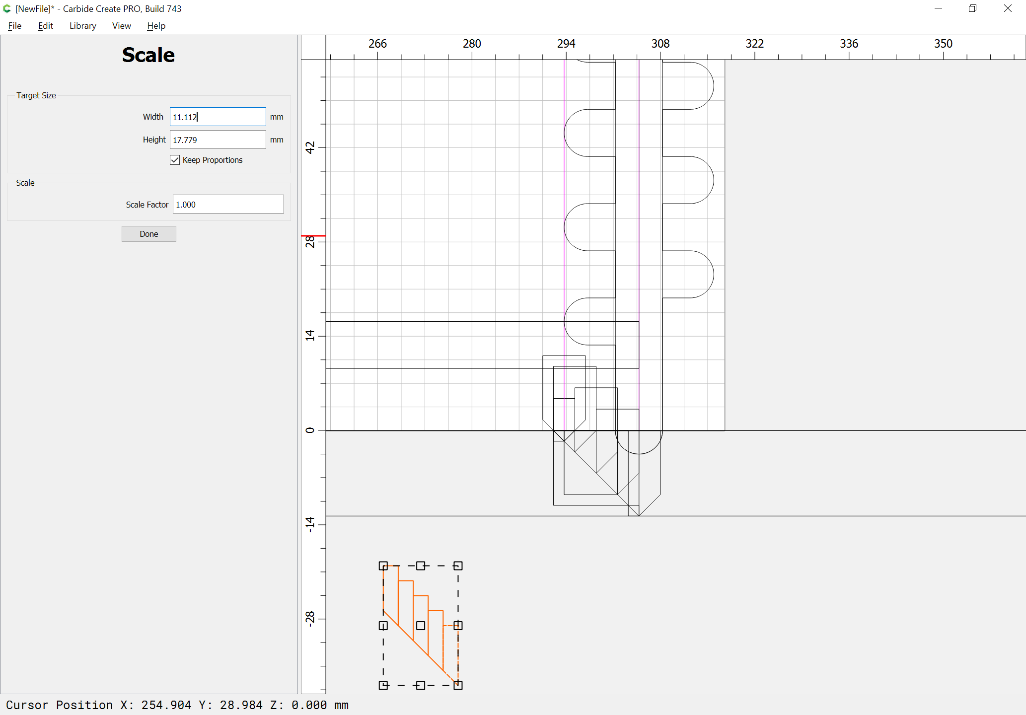
and scale the collection to that width:
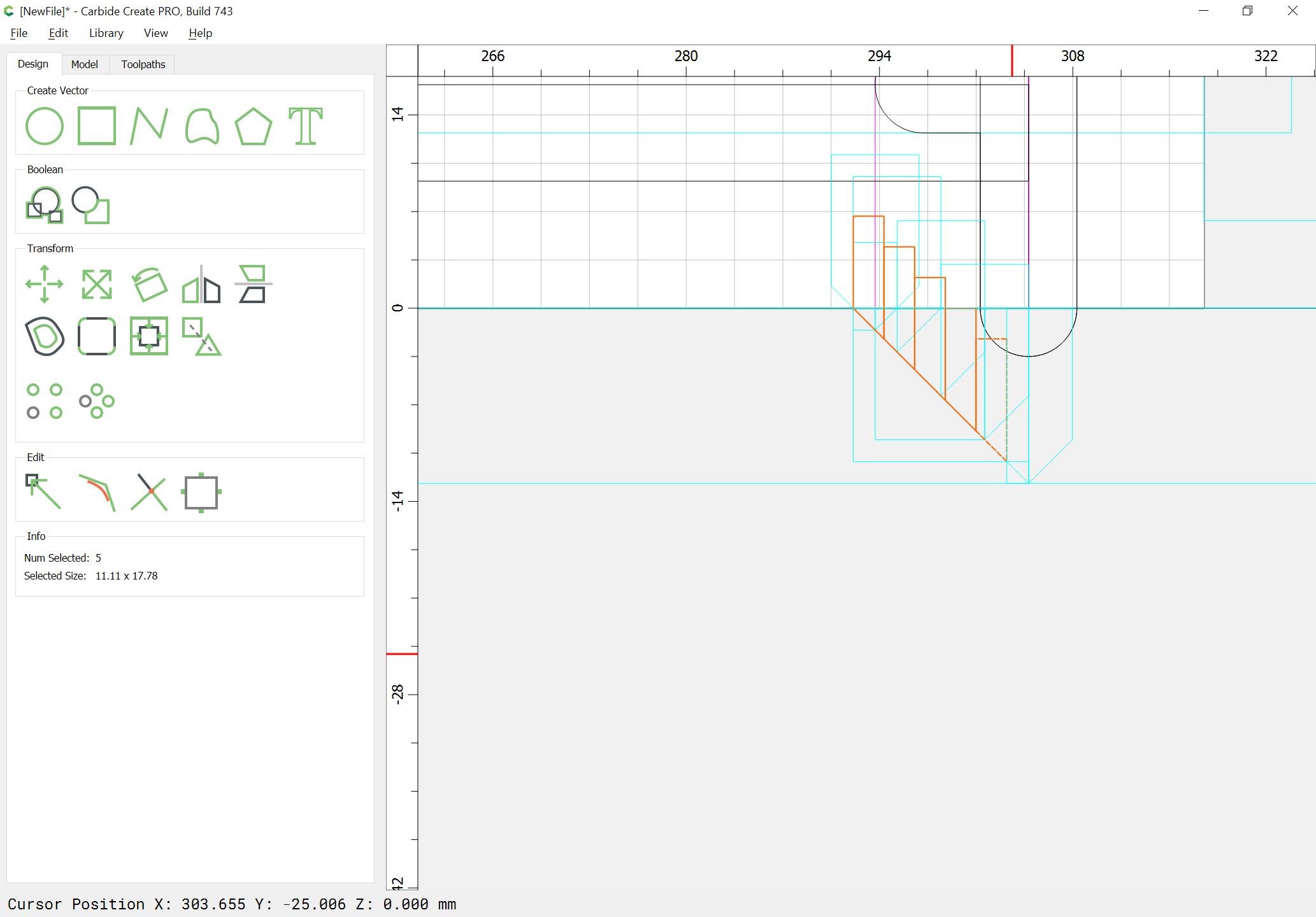
Position it relative to the Layout:
Draw a line which reaches to the bottom of the rabbet from the bottom of the board:
and position it relative to the V endmill proxy horizontally:
and aligned against the bottom of the board:
and assign it a V toolpath which cuts as deeply as the endmill proxy is positioned:
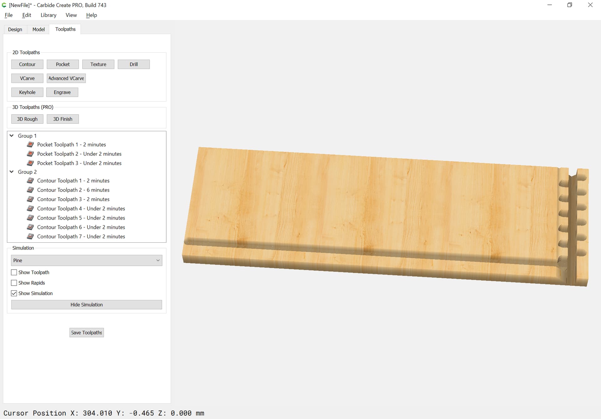
Repeat for the other endmill proxies and we have a preview which pretty much looks like a joint:
Duplicate these at the proper length at the top of the board, then transfer all the geometry to the appropriate ends and you have a set of parts which when cut out will fit together to make drawer sides.
Very thoughtful and elaborate. I realize you only designed this, but do you have any pictures of what the assembled joint looks like? Doesn’t have to be for these dimensions.
I’ll have to model it in OpenSCAD for this specific joint — will do that this evening.
This topic was automatically closed after 30 days. New replies are no longer allowed.