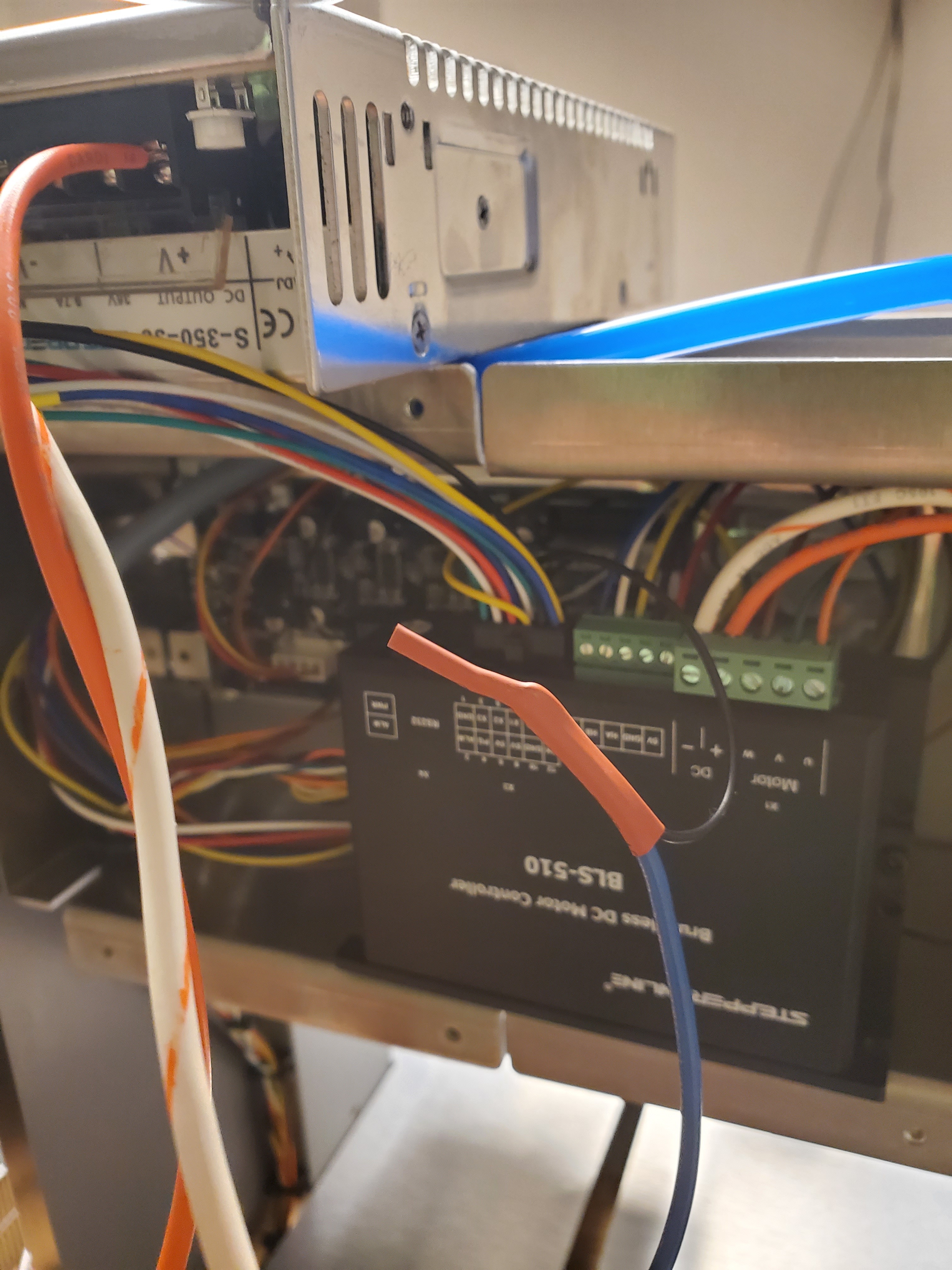
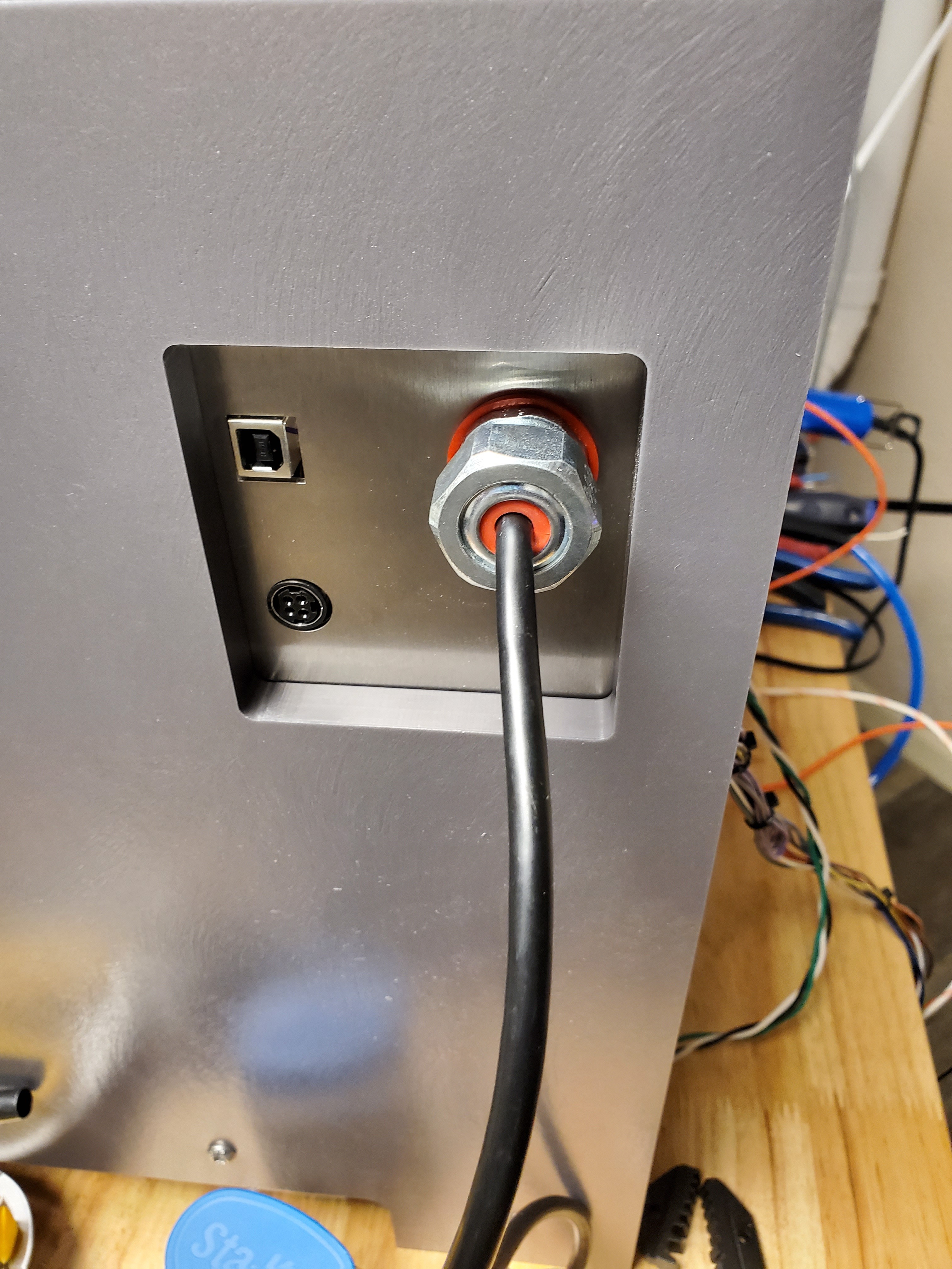
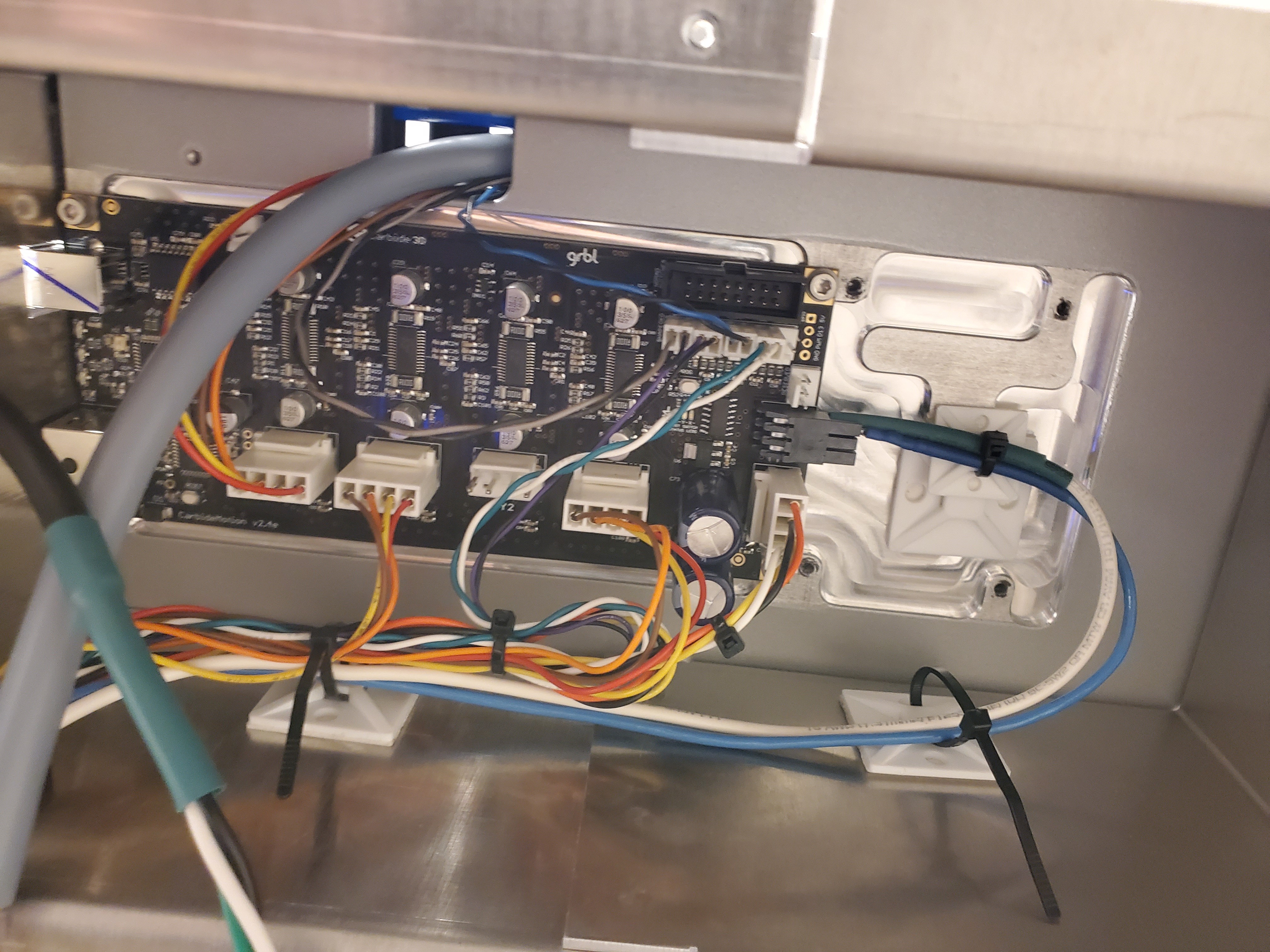
I would like to find out what the pinout is on the board for this connector. I’m sure it is fed 24v, 0v, 5v pwm. But I would really like a diagram that tell what each is. If pin 5 is 5v, is pin 6 another 0v from the 5v ps?

1 Like
Can you go to “McGillicutty” and get that direct?
I tried searching online I was not having any luck but @TonyDangerCoiro got me over my issue I was having. See I was under the impression that low voltage circuits and higher voltage needed to be separated but in fact it was creating the loop that allowed the pwm to correctly control the speed. But still knowing what’s a Hangouts are would help someone in a future build. Like now since I know that there is 24 volt * 0 I’m going to use that to trigger my power supply on and off with the machine so I only have to hit one power button.
1 Like
You don’t provide enough specific information to do a proper search.
Wouldn’t it be easier to get a controller that is popular and supported by the manufacturer?
well the problem with that is carbide3d does not sell an upgrade for the controller but what do is make a very modifiable machine that can be changed if you see fit. the spindle on the machine is very basic, do you own a nomad? do you enjoy needing hearing protection when machining aluminum? i know have a choice because i redesigned the spindle into a more robust set-up and even with the motor that came with the nomad it cuts better and most of all sounds better!! i can run the machine at night and my better half doesnt have the urge to go upside my head for milling at 1am in the morning. now my goal is to be able to make a part in 1/3 time.
Attention grabbed! Care to share motor/spindle details?
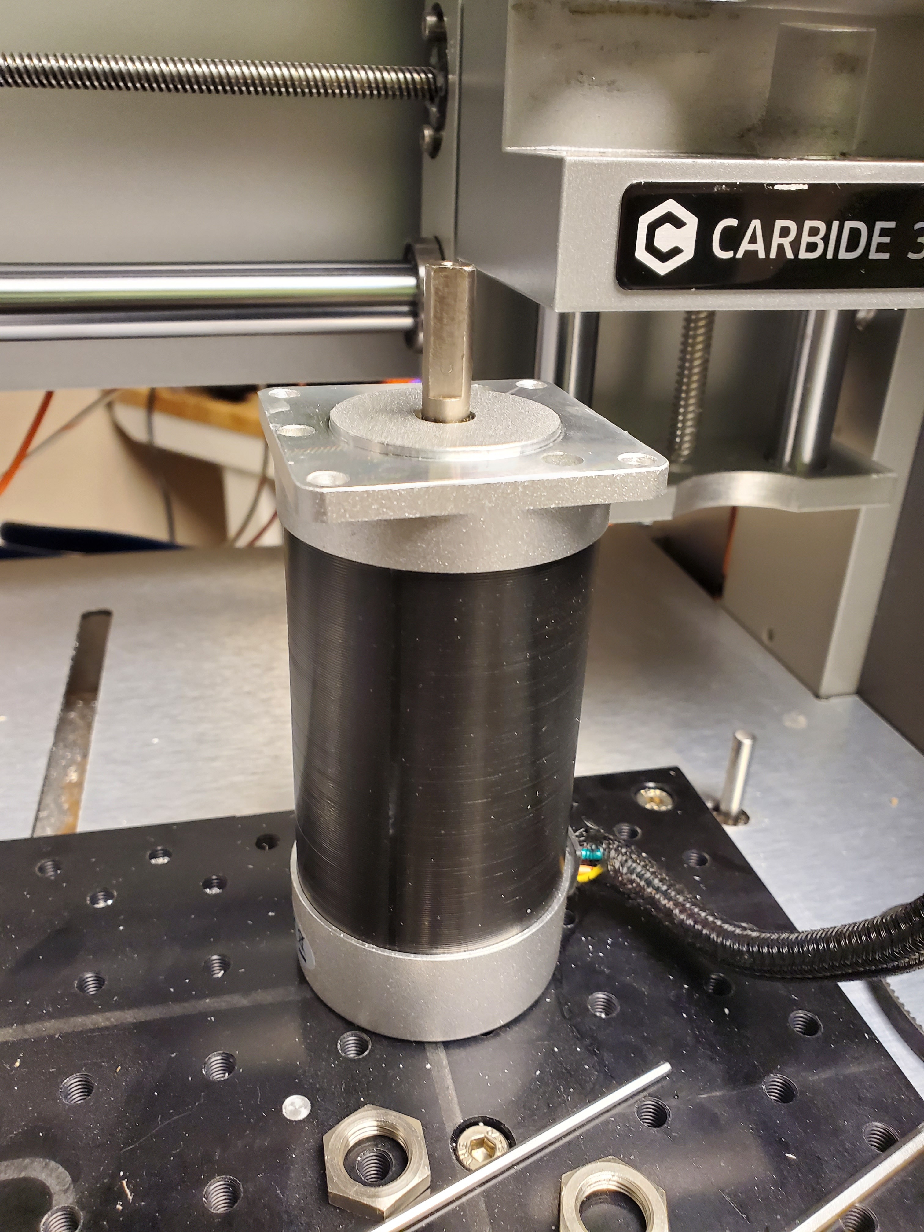
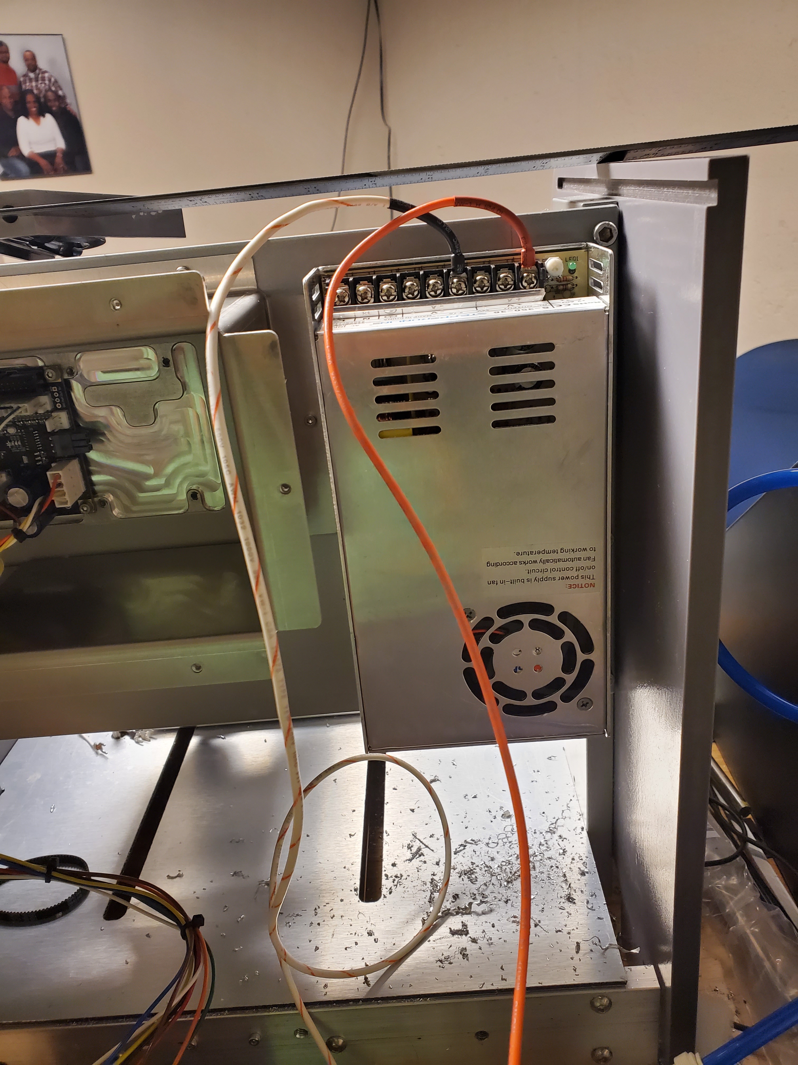
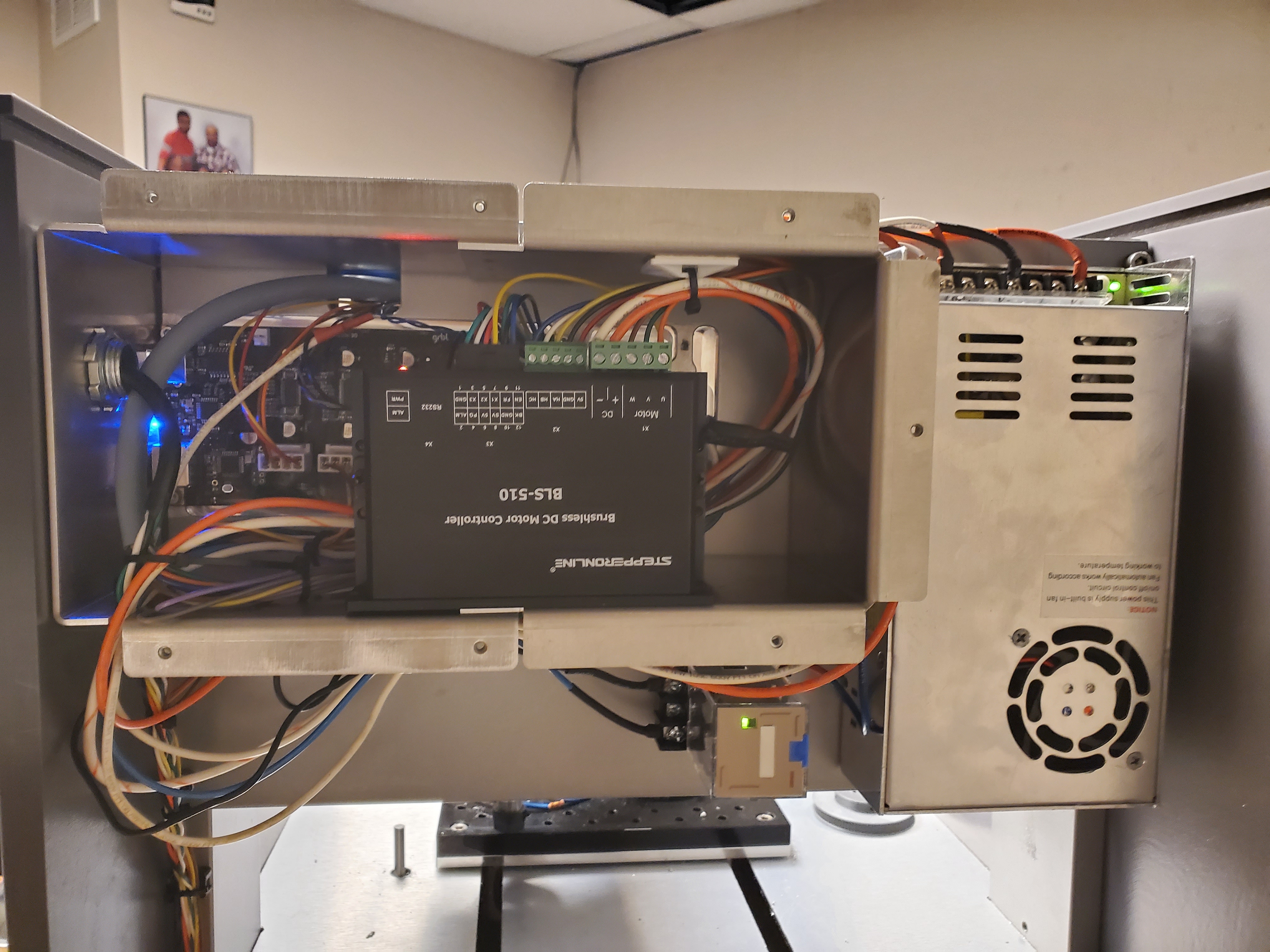
so im using a bls-510 driver and 57BLR110-36-01 bldc motor from stepper online. my step up is causing alot of need to modify the gaurding because the motor is much longer than the stock and i also want to mount it vertical up Vs down. i would have had to make my spindle body longer to accomidate the motor length but i would we sacrificing z height even more. the use the driver and motor it does req 48v ps, which i am grateful that i can mount next to the control case because it is just the right size.
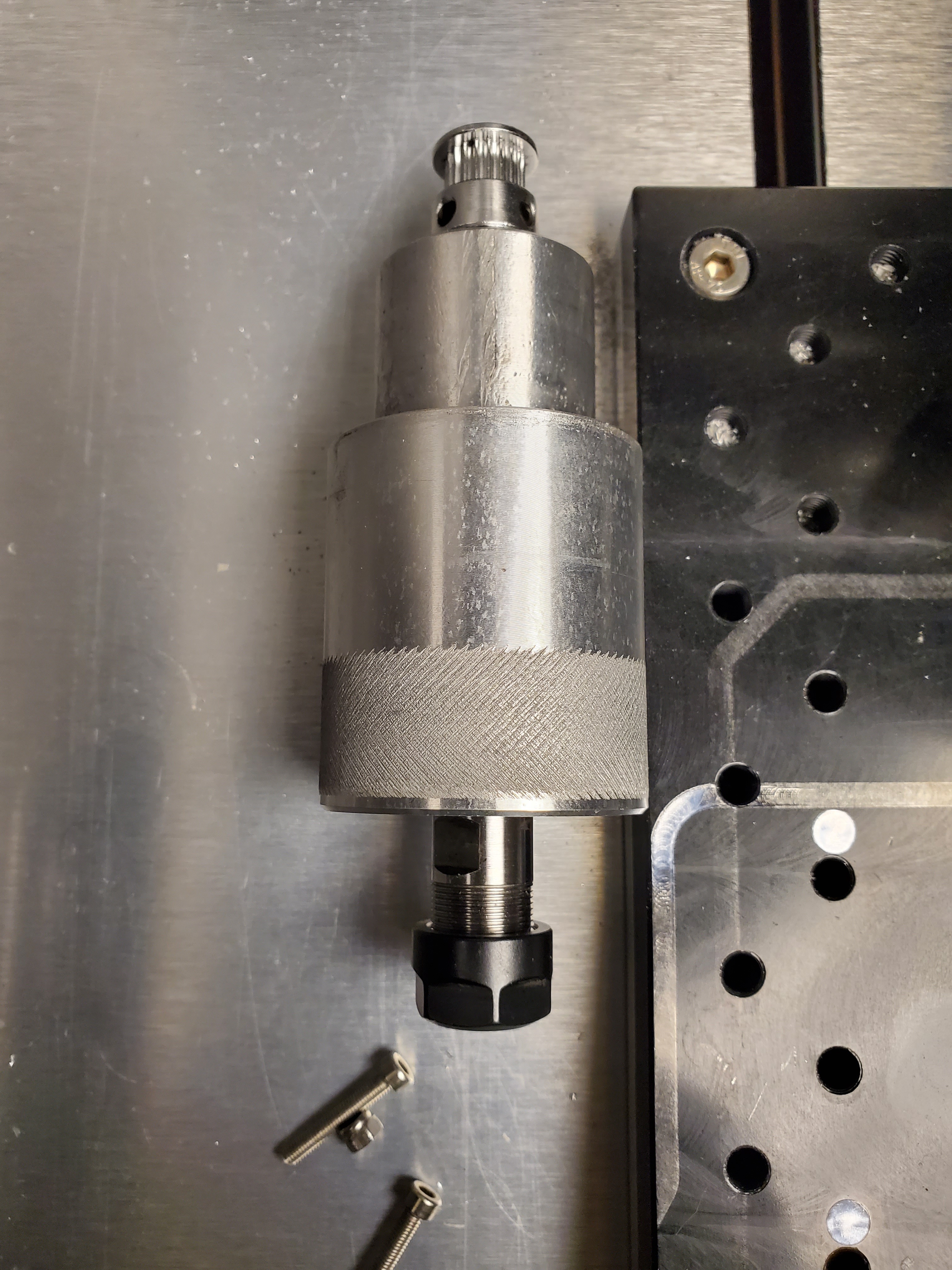
for the spindle, my very own design, collaborated with @TonyDangerCoiro. we kinda bounced some idea off one another for the interior. we each actually made one! my design have 3 bearings, 2 ac bearings and 1 radial. i did increase the diameter of the spindle quite a bit and had to also machine the lower carriage plate for clearance. but i did say that i want to make this into a small powerhouse.
Beauty! I love the direction you and @TonyDangerCoiro are heading in. Have too many other things going on to pitch in but I have to say I am admiring from afar!
2 Likes
This post has kind of morphed to me just sharing this journey. With the covid-19 crisis kind of hard to get items but I am going to MacGyver the hell out of this.
3 Likes
Video of it humming
1 Like
Going to link a few videos of the new setup running soon
2 Likes
This is pretty fantastic! We gotta keep this topic open long enough for videos and demos of how it all works out… especially if smoke starts pouring out of the control board! (which it won’t!)
2 Likes
I have a been trying to wait for my bee pulley but I will this weekend with the 3d printed one
1 Like
On the original subject, did you figure out the pinout of the McGillicutty board @DEDynamics?
I’m considering using a new controller and if I do I’ll need to figure out how to wire the spindle.
4 is 24v, 3 is 0, 5 is 5v… Only ones I use. Think 2 is reset
1 Like
Ah, are you just using it for power for your spindle? How do you control your spindle speed? Is there a PWM output or something somewhere?
I only use the 5v n the 0. The 5v is the pwm.
This topic was automatically closed 30 days after the last reply. New replies are no longer allowed.