MeshCam on a fancy piece

Can someone help me figure out how to set MeshCam to properly machine this part ? The STL file is here:

(sorry for the dropbox link; the file was a tad too large to be uploaded on the forum)

If I were to do it manually, I would focus on the top side first, carve the inside of the bowl, then pocket the holes at the bottom then the central hole and finish with the outside (keeping holders at the bottom of the stock). Then I would flip the stock and mill the convex hull of the bottom of the bowl.

I have not found how to have MC do that properly. It insists on carving around the bottom pockets from the top onward, resulting in a lot of time wasted with lots of fast moves. The pockets at the bottom are not carved out; MC revolves around the edge which is very dangerous as the “cylinder” centered on the pockets will be tossed around by the end mill.

Any suggestion very welcome.

@TotallyFred, if you did the CAD for this part I would suggest exactly what you would prefer to do.

  1. Make the bowl without the holes (actually rounded radial grooves intersecting the bowl) and machine it two-sided.
  2. Model the grooves only, in a solid that represents the rawstock from step 1. While the stock is still clamped from the bottom side of step 1, machine the grooves selecting “don’t machine top of stock”.

If I were called on to machine the STL as you have presented it, here’s how I’d do it.

You are correct in that there will be pillars of material in the center of the pockets. This should not be a problem becuase they are solidly anchored and will drop out of the part soon in the second side machining. With the interrupted geometry you will not avoid many retracts–that is part of the CNC game (unless you can do the two-part machining above).

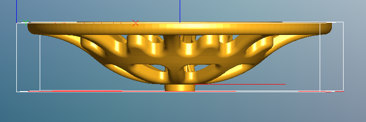
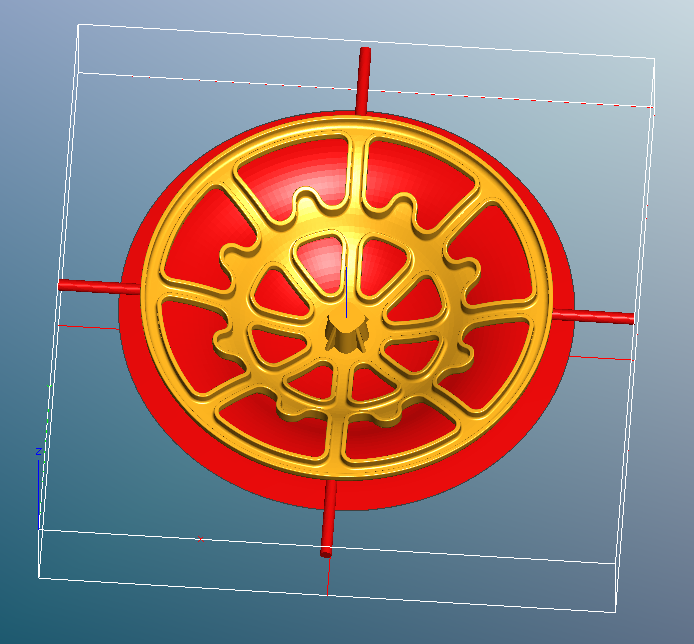
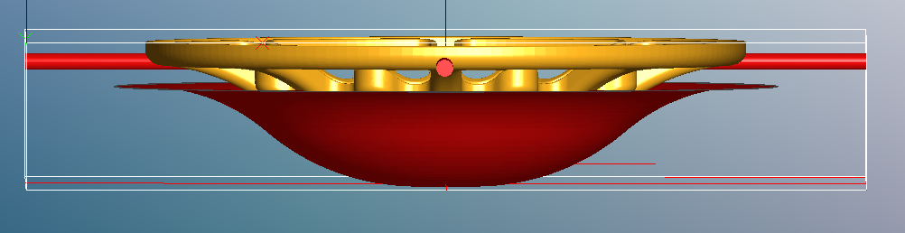
I defined a rawstock comfortably larger than the bowl in X and Y and just a little thicker in Z. I created four thin, wide supports at the top of the geometry. They are inconsequential for the top side machining, and will only come into play at the very end of the bottom-side machining, where the toolpaths have already intersected the first-side toolpaths so there is very little stock remaining to machine and thus low forces.

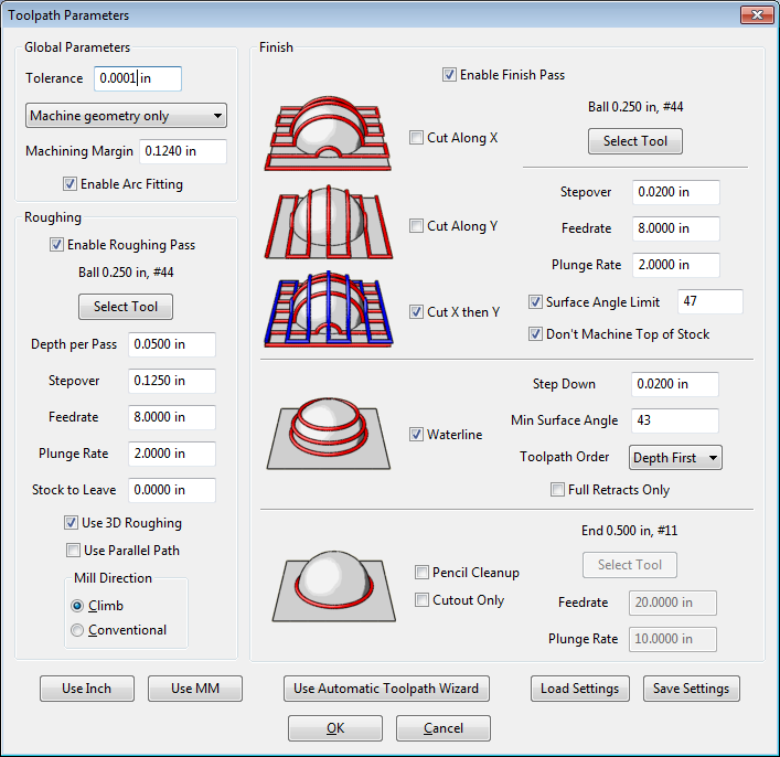
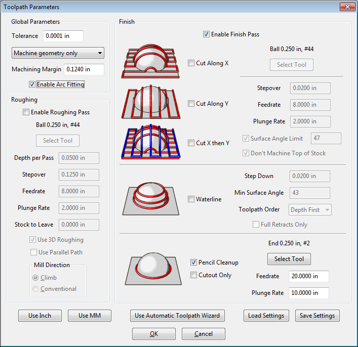
My favorite technique for this kind of part is to use Macine Geometry Plus with a margin of just less than the cutter radius. MeshCAM always operates on the cutter centerline, so with a .250" ball-end cutter (which I will use for roughing and finishing) I set a margin of .124", so the cutter will just barely fail to fall off the edge of the part. This way I can leave Max Depth at the bottom of the stock so I can clear out the inside of the bowl without a lot of unnecessary machining around the edge on the top toolpaths.

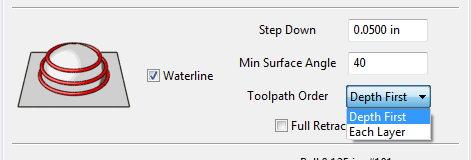
Here is the toolpath parameters screen

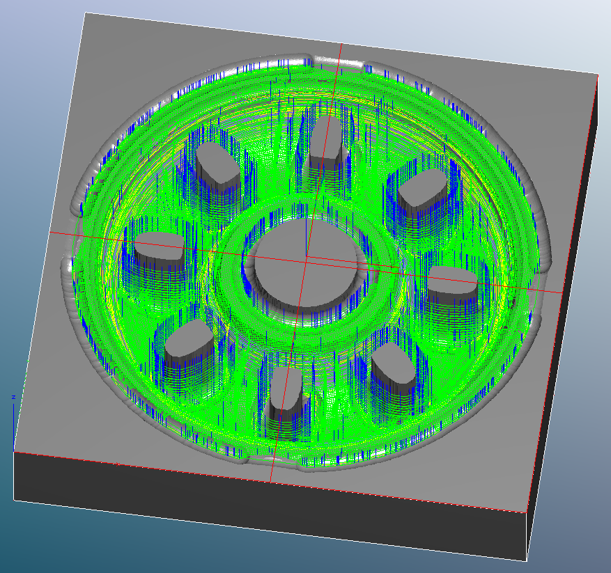
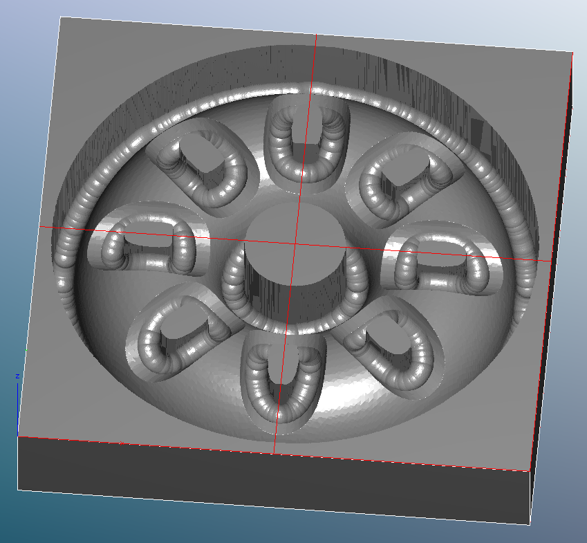
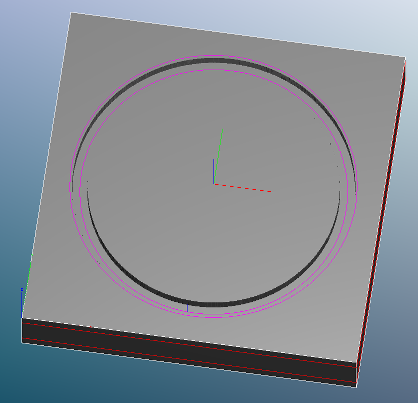
And here is the top machining with and without the toolpaths showing

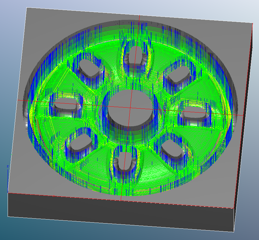
Here is the bottom side machining with and without toolpaths showing

In reality the pillars inside the pockets will fall out as soon as the tip of the ball-end toolpaths intersect the toolpaths from the top side machining. The top and bottom toolpaths will ultimately leave just a little edge to deburr because there is almost 100% overlap of the ball end from the two sides.

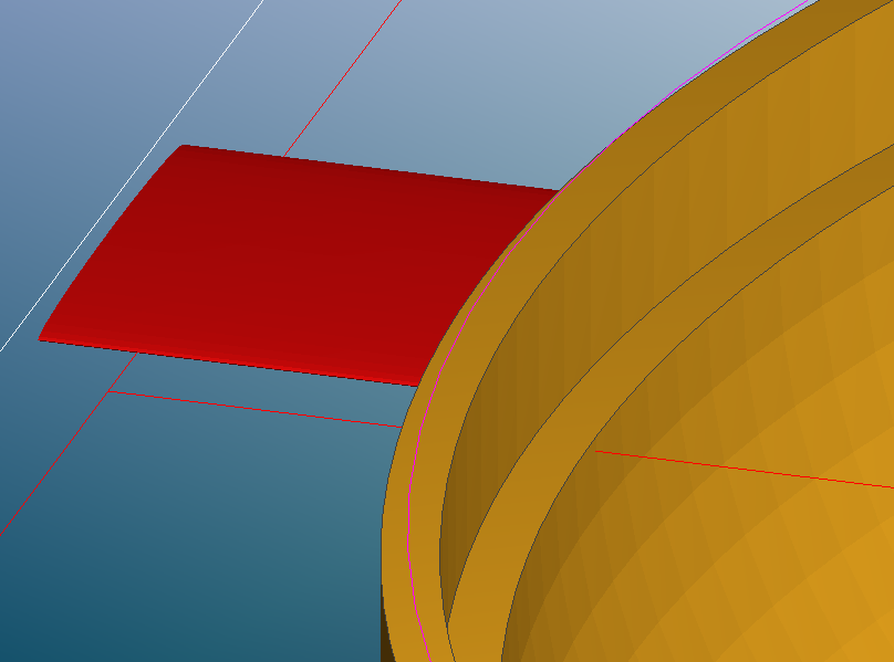
Since I have used a ball-end cutter, the shelf on the top side is bridged over. I do that with a second MC job, single-sided in this case. I set a Max Depth just below the shelf, and defined a Machine Region superimposed on the top face of the bowl. The Machine Region is the magenta circle hovering over the bowl rim, and the Max Depth is the red line intersecting the bowl just under the shelf.

I used a square-end cutter (in my case also .250" diameter) and the toolpath is a single circle

I would run the “shelf job” after the first side bowl machining while the stock is still clamped in place. There is little material to actually clear, so no roughing is required, just the pencil finishing.

Randy

2 Likes

Thanks!! The .124’’ margin is a genius trick! I initially put the shelves at the bottom to reduce the fast moves but this is way better and cleaner since the shelves now reach out perpendicularly to the part (easier cleanup) instead of tangentially.

I will try both methods to evaluate which one is faster in the end (machining + operator). I like the idea of using MC only after the STL is done as it is a single tool to go through (two with the gcode feeder) whereas creating incomplete parts from the CAD involves an additional tool and more files. I guess with a little prep, both can work. Let’s see what my brain can cope with better :smile:

thanks again!

You’re welcome, Fred.

There is another tool you could use, called a Check Surface. This isn’t really well documented, but you can model a second STL representing the maximum depth and superimpose it on your workpiece STL. MeshCAM will not treat the Check Surface as part of the geometry, but will treat it as kind of a parametric Max Depth. You can bridge openings, and make a “flange” around the part perimeter. Then you can use Machine Geometry Plus with a reasonable kerf around the part.

I have used check surfaces in the past on parts like yours, dished and with openings, but can’t find a post on the MeshCAM forum. Robert’s blog post where he introduced Check Surfaces is at http://www.grzsoftware.com/blog/development/check-surfaces/ and there is an example shown in the MeshCAM forum thread http://grzforum.com/viewtopic.php?f=3&t=1160&p=2628

Randy

1 Like

Very interesting! Took me a while but I just found the option. It is in File -> Append Check Surface. Will play with it tomorrow (4AM… again).

While searching, I tested the Cap Holes tool which seems to convey some element of Check Surface but it does not optimize the code; even though the end-mill won’t go below the red surface (the capped hole), MC still “sees” the holes beneath and works around them. It only seems to see round holes anyway not the elliptical pockets.

I also tried slice geometry which will split the STL geometry and save it into N files. This is prompted an interesting idea: it would be very convenient if we could virtually slice the geometry and ask MeshCam to treat the slices independently. Somewhat like exclude region but along the Z axis. We should be able to stack the jobs to be excuted slice by slice.

So surely, I set max depth to 13mm and the top of the bowl is machined like it should (2 “cylinders”). MC ignores the pockets beneath!! yay! Useless in my case but yay anyway.

Now think of a slice as a normal job having a “max depth” and a “min depth”.MC should be oblivious about what is below max depth (like today) and aware of what is above min depth to avoid intersecting with the geometry above it.

I guess this is a feature request :smile:

Fred, yes, Rob introduced hole capping along with hole drilling. It is specifically to cap holes that will be drilled, to mill the bulk surface without falling into the holes. MC does a pretty good job of capping holes even on contoured surfaces ( http://grzforum.com/viewtopic.php?f=3&t=15083&p=22686 ) but there are a couple limitations:

  • The holes must have a circular projected shape from the top view.
    I.e. MeshCAM will only cap holes it can detect as drilling
    candidates.

  • The holes must be continuous, i.e. a hole with an intersecting slot
    like a keyhole won’t be detected.

For anything more involved, you need to create a check surface. Check surfaces explicitly are not treated as geometry, rather are considered a non-horizontal Max Depth surface. So Machine Geometry Plus only treats the actual geometry.

Side note–that is a reason why modeling supports does not go well with MeshCAM. They will be part of the geometry and MC will happily mill around the end of the support, so you’ll have your geometry with protruding spikes at the edges. :smile:

A limitation of my “don’t quite fall off the edge” technique, is that it only works with geometry that doesn’t have any vertical surfaces around the perimeter. The vertical surface will not be milled.

A few years ago I did a “fancy piece”, a railroad car brake wheel that was dished, had many holes in the geometry, but also had vertical walls at the perimeter.

Rather than doing a two-sided job, I needed to do two single-sided jobs, with modeled check surfaces for each to provide the contoured max depth limit

The top side:

And the bottom side

This was about 2.5 inches diameter, and to be a master for investment casting. Rather than spending 20+ hours machining it from brass, I talked the friend for who I was doing the modeling, to have the master done in stereolithography at Shapeways.

But this is how I would have approached the machining.

Randy

It is a very nice example. Yes, I see how to use the check surface tool.

Now do you also think it would sometimes be more efficient to give meshcam the volumes to mill out rather than the volumes to preserve ? I.e. It seems easier to describe an efficient job as a collection of “3d holes” to be done one after another rather than letting MC guess by the look of the target shape ?

MC currently seems to perform 2 high level tasks:
1- analyze the solid geometry and figure out what to carve out (“empty geometry”)
2- generate a path for the carved geometry

While this is intuitive for the users, it is not easy to optimize.

It would seem a good idea to provide a list of “empty geometries” to help MC and let it optimize a toolpath for each of these 3d holes. Essentially saving MC the guesswork of step 1 and having step 2 focus one one empty geometry at a time (saving jumps etc).

@TotallyFred I follow the workflow where I specify a single ‘hole/surface’ to work on at a time. This way also helps remove lots of rapids and helps MeshCAM stays focused and on task :smile:

@FlatBaller, you just beat me to a reply. @TotallyFred, FlatBaller is correct in that you can specify Machine Regions. Set a Machine Region to outline one hole, set all your toolpath parameters and generate the gcode, delete the first Machine Region and define another, generate that gcode, repeat as necessary. It is actually fast to do and I have done it on many occasions.

Another thing to keep in mind is to make sure that waterline finishing is set to Depth First. When MC encounters a deep hole or depression it will stay with that one to the bottom before moving on.

Otherwise it will do a given depth all over the part and skip back and forth a lot.

Here is a workpiece where I used the technique, machining one row of louvers at a time

This was for an instrument housing prototype that would ultimately have stamped louvers in it. The actual part is .06" thick with louvers that protrude .125", and I machined the prototype from .187" thick aluminum plate. After I did the louvers themselves, I cleared out the bulk flat area with gcode from SheetCam. I machined the rear side of the louvers using MeshCAM, again row by row, with Depth First chosen also.

Randy