From the documentation page #13 figure #8 the control board is installed on the Y1 axis. On my XXL (belt drive) the board is on the X axis. Can I move the board to the Y1 axis? I would prefer have it on the Y1, that way it will get less saw dust.
The board should only be installed on the gantry (back of X-axis) on a Shapeoko 3 — it should be installed on Y1 (left Y extrusion) for XL/XXL machines and the drag chains and wiring length are set up for that.
Please contact us at support@carbide3d.com if you have any difficulties with this.
Thank you Will. You just confirmed that I built my XXL the wrong way. I will revisit the build documentation and move the board soon as I receive the new homing switches 
Thank you again!
1 Like
Just want to thank the support folks at Carbide3d again for their awesome support!!!
Even a single missing screw is resolved with utmost speed (and i’m in Canada!).
Will do you ever rest?
2 Likes
Yes, I actually crashed early last night (my full-time day job has been going full-tilt for a while now and I decided a solid 11 hours of sleep was what was needed to keep myself from making errors).
5 Likes
The proximity switch requires a complete disassemble of wiring. If you are going to move the controller that is the time to do it.
1 Like
Hey guys, does anyone have a picture showing where the y axis drag chain tail plate goes? I apologize-I’m likely overlooking something, but on page 13, figure 8, it shows that the front on the tail plate should be 15.5” from the front of the machine. It looks like that image is on an XXL, and if I go with that dimension on my XL, it will put the plate a little bit rearward of the backside of the control board. Is that correct, or should it be more toward the front of the machine. If I weren’t upgrading to the new control board at the same time as I’m installing these switches, I think I would have kept it in the same spot as i did before. Again, I apologize as I’m sure there are some instructions that I overlooked. Thanks for the help!
Rather than a photo or measured position, I’ve always:
- mounted drag chain on gantry
- moved gantry all the way forward — note where drag chain naturally falls
- moved gantry all the way rearward — note where drag chain naturally falls
- test with drag chain at a position in-between the two points — if need be, remove one or more links
1 Like
Ok, I got everything out together tonight but I have one of the issues I see a lot of on this site. When it goes to do the homing cycle, I’ve had a multitude of different errors as it works on the z axis. I’ve seen these errors: (1) homing failed, couldn’t find limit switch and (2) homing failed, pull off didn’t clear. Sometimes the z axis goes up, sometimes it goes down. There have been times when it’s vibrated some and others when it’s been smooth, but it always ends up giving me one of these errors. I will let you know my setup and what I’ve checked so far, and see if anyone has any ideas.
-what I have been running-XL with touch probe, bit setter, HD-Z
-new upgrades as of today-new v2.4 board and the new proximity switches
-Updated to the news v5 carbide motion
-went into settings and made sure my bit setter was unchecked, sent the new configuration with the XL, HDZ
-limit switches all turn red when I place a piece of metal close to them
-the appropriate light turns blue on the board when I put a piece of metal near the switch (the z is the left most light, then y, then x, which is opposite of the way they are plugged into the riser board above)
-I saw where a guy had an issue with the riser board being wired incorrectly, but I assume mine is ok since the locks for the connectors on the riser board are on top
-I can move the hd-z axis by hand when it’s unplugged, so I don’t feel like it’s a mechanical issue
-also I did have a similar issue to this last weekend with the old mechanical limit switches and old board, which was the thing to push me over the edge and order new-I was hoping I would get lucky and it would work, but not the case-it seems like the only things I didn’t change out (electrically) were the stepper motors and their cables, so I can’t understand what I’m missing
I’m not the best at troubleshooting these but I sure love my machine. Thanks a ton for any advice you guys can give!
Check your wiring and connections on the Z motor.
2 Likes
Thanks Neil. I will check it out more in the morning. I can check for continuity on the grey cable from the motor to the board easy enough. What should I do to check the motor itself?
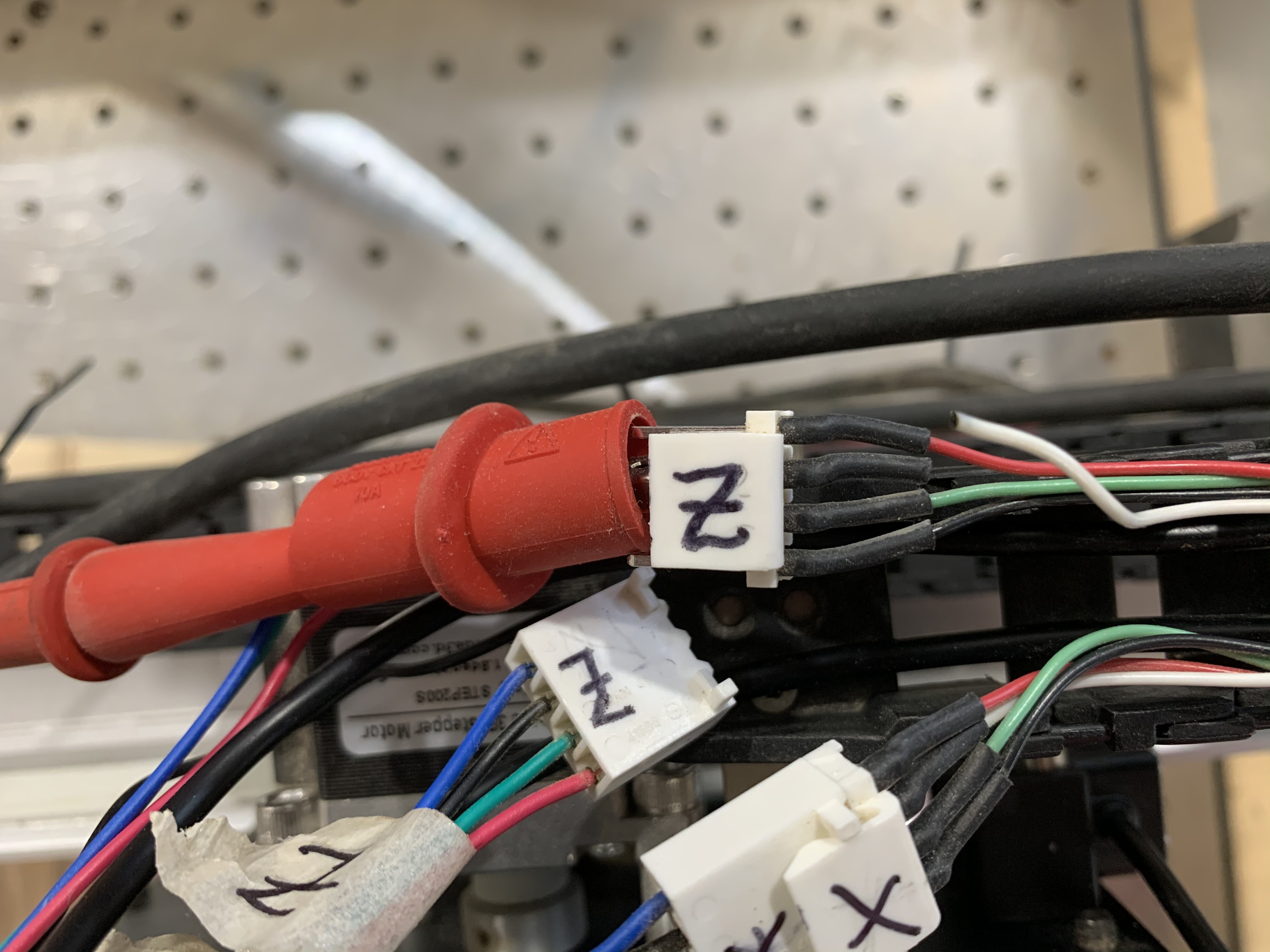
@neilferreri thanks Neil, you called it as normal! I have always looked toward limit switches and thought if the z axis was moving, then it was probably ok. A quick continuity check showed that the white wire on the z axis cable that goes toward my board was not reading, so I pulled in the wire at both ends. Sure enough, the motor end popped out as seen in the picture. I’ll try to fix it up after breakfast. Thanks again, I owe you!
3 Likes
No problem. Any time you get those sporadic stepper motions, it’s usually a wiring issue. Becomes a real pain to track down when it’s actually a wire broken inside the insulation.
Up and running again?
1 Like
I finished soldering it before needing to run an errand for my wife. Now, it’s time to watch some college football before testing it out at halftime I hope. I’ll report back in a bit.
@neilferreri. Yep, just initialized, recalibrated the bit setter, and look to be good to go again! Thanks for pointing me in the right direction!
2 Likes
I got my replacement sensors blazing fast - thanks a million to Carbide3D Support that continues their track record for being the best in the biz.
I was able to get it all set up with no issues - I had a close call with my bitsetter that was off a bit on its XY zero, but luckily was close enough not to crash.
5 Likes
This topic was automatically closed after 30 days. New replies are no longer allowed.