Mod Questions for my XXL Table

I really like the idea of a “floating bed” inside the frame. One that could be lowered to accommodate a larger item being placed beneath the router while at the same time not having to debate if having a waste board on top is worth the loss of Z height. I have considered using a coffee table lift in a box beneath the table. Has any one actually attempted this sort of modification? Stability of the work surface and of the frame itself if the majority of the stock waste board is removed are my primary concerns with this one.

I want to incorporate the ability to do jointing. I have debated either creating a pass through slot in the table, or rigging up a clamping system to the front and taking advantage of the overhang. My primary concerns here are that between the quality of lumber and help I used to assemble my table, I don’t really trust the trueness of that front surface to mount directly to it with a simple set of clamps.

I also need to design an enclosure for my vacuum to dampen the noise. My primary concern here is restricting air flow and burning it up prematurely. I am using an intermediary dust collection system to extend the life of the filter.

Any advice, tips, tricks, or pics of your successful or failed attempts at these would be very appreciated.

I have a jointer but I also have a router table with an Incra Positioner. My fence is split in the middle so I could edge joint by moving the in feed fence back so after the piece passes over the router bit the output side will support the work. You can do a lot of things on a CNC but sometimes the effort is not worth the trouble to do it. A regular router fence can work if you split it in the middle and add shims to the out feed side and line up the bit with the out feed side. You can made a router table from a piece of plywood, make a fence for very little effort and have a jointer. The larger the bit on the router table makes a better jointer rather than using a small bit. However both will work. The reason a larger bit works better is the bit is traveling faster on a larger diameter bit as opposed to a smaller bit traveling slower for the same rpm of the router. A bit with a bearing aids in lining up the fences to the bit then you can lower the bearing down below the table and joint away.

As much as I would love to have a fully functioning workshop, it’s just not in the cards for me at the moment. Aside from a few saws and drills, my Shapeoko is my wood working equipment and I am not in the position to add anything else at the moment.

I have a vertical clamping jig on the front of the machine, which is all bolted down to the same torsion box table.

If you’re trying to go below the main baseboard of the Shapeoko, the main function of that and the steel straps is to hold the machine itself square and level. Whatever you do to open up a gap under the machine for deeper workpieces you’d need to figure out a suitable way to replace that function.

Rather than a lift perhaps a top table which is removable and a lower table which is accessible when it’s removed? That way it’s much easier to keep everything rigid and aligned?

1 Like

You have a router in the Shapeoko which is removable. A piece of plywood with hole and mounting holes would work. The fence would be simple to screw together with the fences separated in the middle. Take a look on youtube for ideas for a simple router table.

I will note that if you’ve had to go to any efforts to tram the router (or even if not), one may have to repeat those efforts when reinstalling it.

Also, the mounts have soft aluminum threads and will be worn out by repeatedly releasing/retightening esp. if care isn’t used to align the threads just so.

A second router is a useful tool, and it can be justified as a hot spare.

Thank you. What I was asking about as far as the jig was, what did you do to ensure that the jig was flush with the router?

As far as the cutout, that is basically asking about. If anyone had done this, what did they do to keep the frame stable.

The problem with a two tier table is that It would only allow two set heights. Anything else would require a collection of intermediate blocks to adjust the height. Other than the easy way out of buying a prefab option, I have considered a gear driven table with threaded rods on each corner. I just figured that with all the clever people here, that I can’t be the first one that wants to attempt it.

That is an option, but as @WillAdams pointed out the process of removing and replacing the router is not really advisable or simple. I appreciate the suggestion, and maybe at some point I will attempt the router box option, but I can’t see how making a box and jigs, then doing a repetitive multi step process manually could possibly be the better choice. The entire reason CNCs exist is to eliminate things like this.

Honestly, I am not concerned at all about the machine being able to do the process. The design is extremely simple in reality. Carbide Motion doesn’t really care about the geometry of the bit, dovetail or otherwise. It just needs to know where to put it. It’s simply a matter of knowing the offset needed for proper spacing and the depth. You can basically draw a line representing the center line of your first cut. Then create an array set to offset the desired distance between joints multiplied by the number of joints you want. After that, it’s as simple is selecting them and setting a tool path for your desired width. It would take a few minutes tops. Create an inverse offset for the other side and boom. Only manual labor needed to do this process are tool changes and clamping your boards.

Based on the fact that the machine was designed with an overhang on the front of the face. I was expecting that many people had probably rigged up some sort of clamping system for their machines. I am looking for tips on the best way to set up the jig in relation to my table to ensure that it is aligned with x and y. My main concern is that since I used less than perfect lumber, anything I mount the front face of my box cannot be trusted to be correct on any plane.

2 Likes

The two issues with that are maintaining the rigid stable alignment of the shapeoko rails and keeing the workpiece mounting rigid and trammed with the machine as you move it. You’d need to properly constrain the moving table in X and Y as well as the Z with the leadscrews, like a lifting knee on an old Bridgeport. That’s quite a bit of engineering to get right as you’re basically adding another axis. That said, I’d like to see it if you build it.

If you mean the vertical fixture jig, there’s quite a few nice ones out there, lots of good ideas to be had from jigs non-CNCers call “dovetail jig” where they clamp vertical and horizontal boards together to cut from the same template.

Mine was fairly simple, there’s plenty I don’t like about the V1, In the spirit of sharing my mistakes so others may learn and make different ones though;

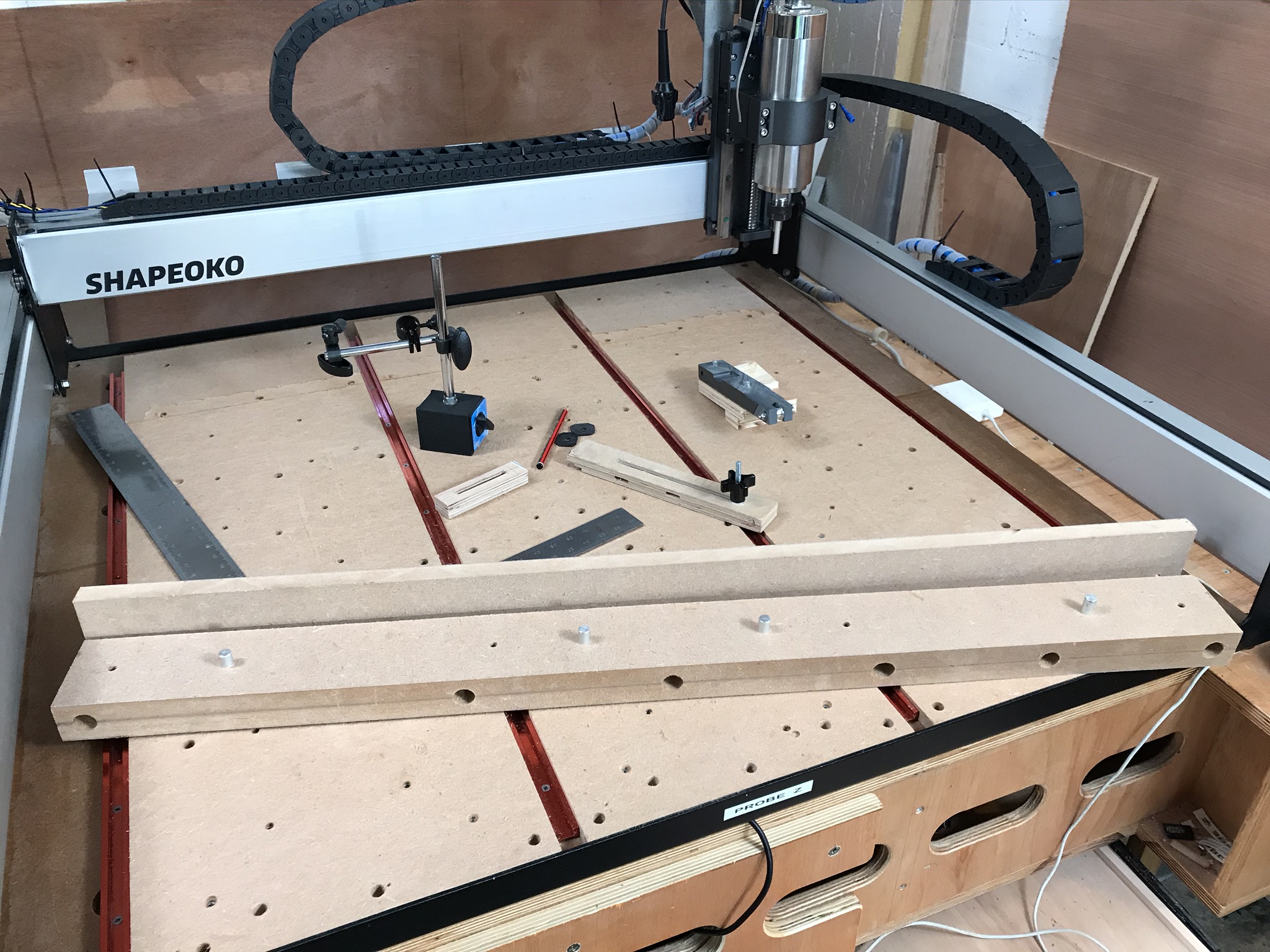
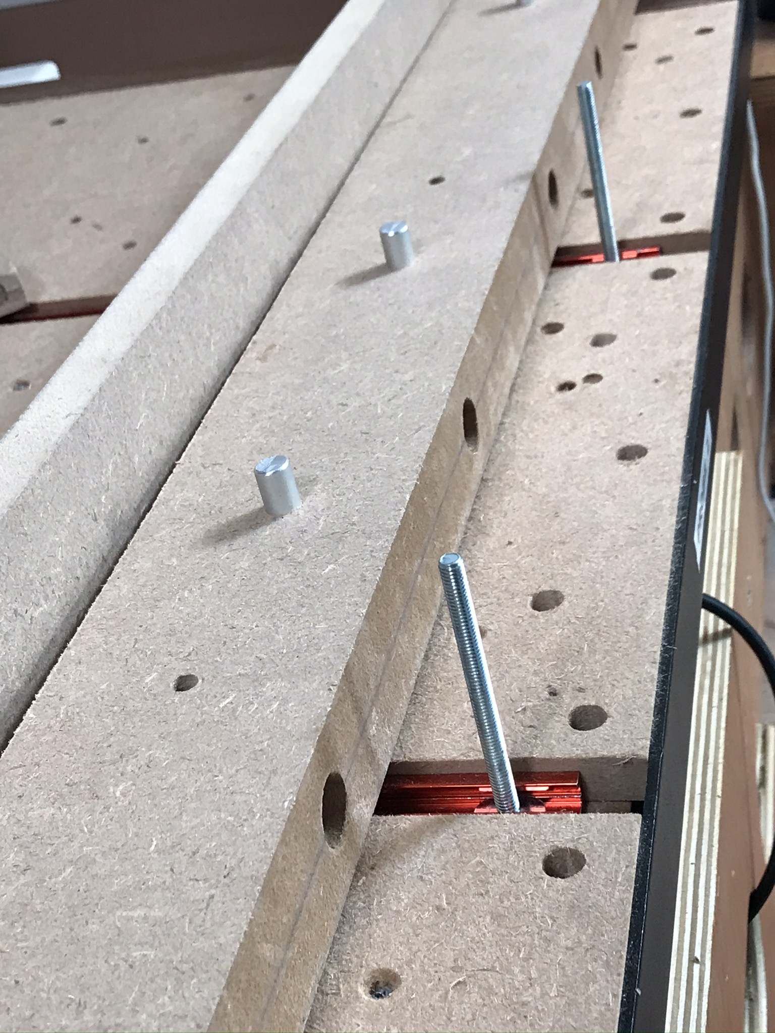
Two layers of 18mm MDF glued together, I had the Shapeoko cut four matching 8mm holes in the bottom of the jig and the spoilboard so that it could be repeatably positioned on the front of the machine using 8mm Aluminium rod.

There are tee-bolts from my T tracks to clamp it down on the front of the spoilboard. It’s on a levelled part of the spoilboard so it’s flat in Z and consistently in the same place when I use it.

I cut the MDF to deliberately overhang the front of the machine by a few mm and then used the Shapeoko spindle to cut the front face parallel with the X rail. This is where you find out how well you’ve trammed and whether you’ve balanced your Y belt tension left to right. I planned to re-finish this periodically but I would make it differently now that I’ve used it :frowning:

There’s then holes drilled front to back to allow the front clamp plate to be attached, these have long M8 bolts in but threaded rod, coach bolts, whatever you have available. The Aluminium pin is there as a consistent X stop for doing multiple parts, that was an afterthought.

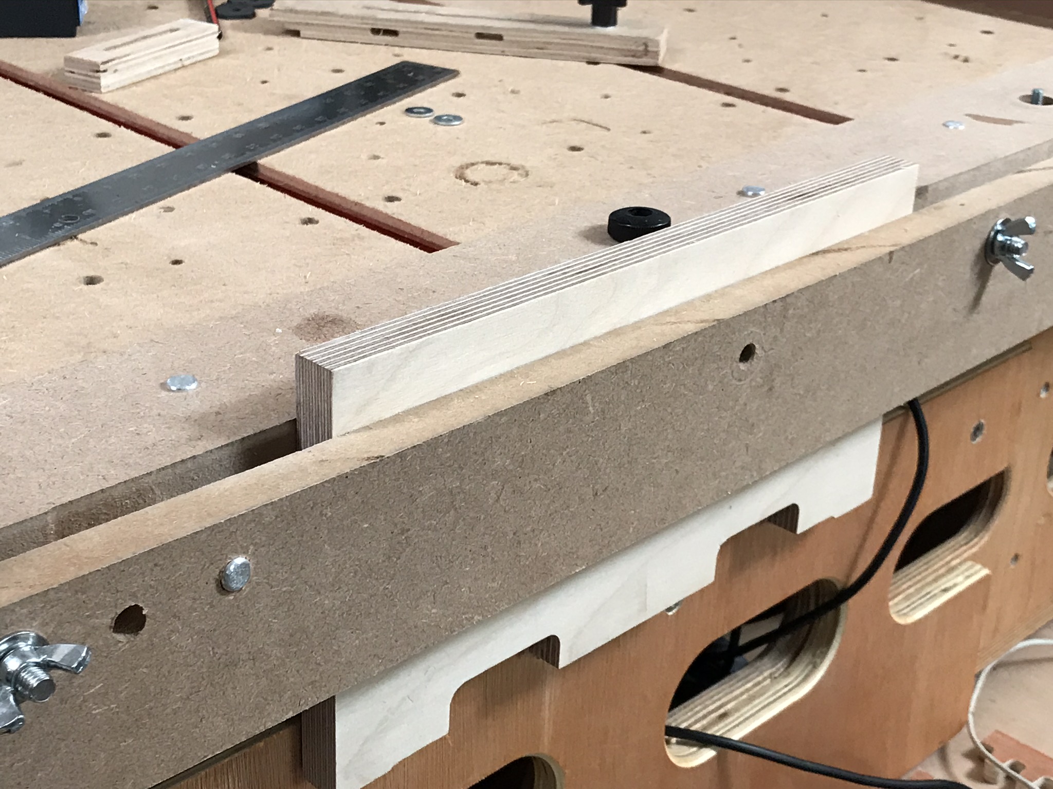
I just use wingnuts on the front to clamp the front plate down, it bends a bit, should have used ply or something stiffer, but it works. There’s a vertical board attached to the bench with lots of holes in so that I can clamp & stablise longer workpieces.

What’s good;

  • It fully removes from the machine
  • It holds work up to the full X width vertically across the front of the machine straight with the X axis and vertical
  • It was cheap to make
  • It’s almost flush with the metal rail meaning I don’t lose any overhand cutting area
  • Most of the parts are MDF so when I crash a toolpath into the fixture nothing bad happens
  • With the HDZ travel I can easily cut 100mm+ into a vertical workpiece, with a long enough cutter (with a large enough diameter for this depth of cut)

What’s not good;

  • I should have thought about repeatable X stops before construction
  • I should have figured out how to provide a vertical stop to get workpieces repeatably vertical without measuring every time
  • The front clamp part is too flexible
  • There’s no real provision for front & rear sacrificial support boards to avoid tear-out doing things like dovetails so you end up trying to sandwich your workpiece between two bits of 4mm ply which makes getting vertical and setting zero a PITA

Does that give you some ideas about what (not) to do?

4 Likes

This topic was automatically closed after 30 days. New replies are no longer allowed.