I just wanted to share my first Nomad project doing PCB isolation milling. Thanks to everyone in the Carbide 3D community that shared their experiences to the forum.

Thank you Marc Liyanage, your demo was a big help.
I just wanted to share my first Nomad project doing PCB isolation milling. Thanks to everyone in the Carbide 3D community that shared their experiences to the forum.
Thank you Marc Liyanage, your demo was a big help.
Nice work! Keep it up!
mark
Any info on bits used, and speed & feed?
How small a track spacing are you able to reliably get?
Just a reminder that milling PCB materials (e.g. FR4, garolite) produce particles (“dust”) which are extremely dangerous to your health. Adequate isolation, negative pressure in the enclosure, and careful vacuuming is necessary for protection. A HEPA filter rated for 0.3 microns is necessary.
mark
I was using 0.1mm V bit (30 deg) from aliexpress. They are usually $10 per 10pc set. Order two sets if you plan to mill a lot because one bit will be gone in 5 meters. You also want to get set of drill bits 0.3-1mm to deal with holes.
Main issue for me is actually PCB “flatness”. You have to fix it flat and check that your wasteboard is flat as well because part of your traces will not be cut through copper. That is because stepdown is usually not more than 1mm.
I was using eagle and flatcam.
I am new in milling and still experimenting but to get traces close than 2mm you have to use new V bit because it ranout pretty fast. I am using G-Wizard to calculate stepover and feedrate.
FR4, Garolite or something else?
Garolite is notoriously hard - it chews tools much faster than FR4.
mark
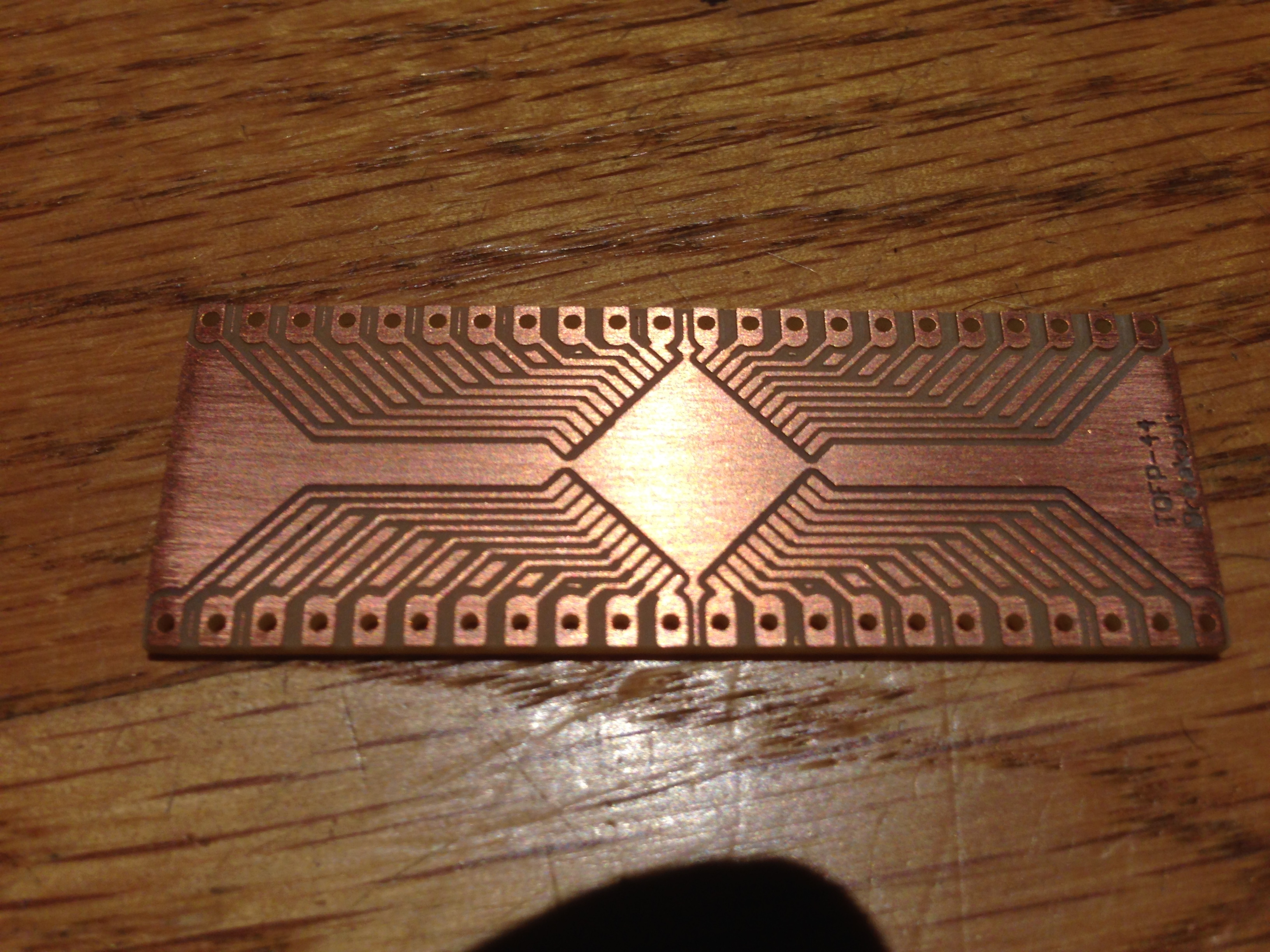
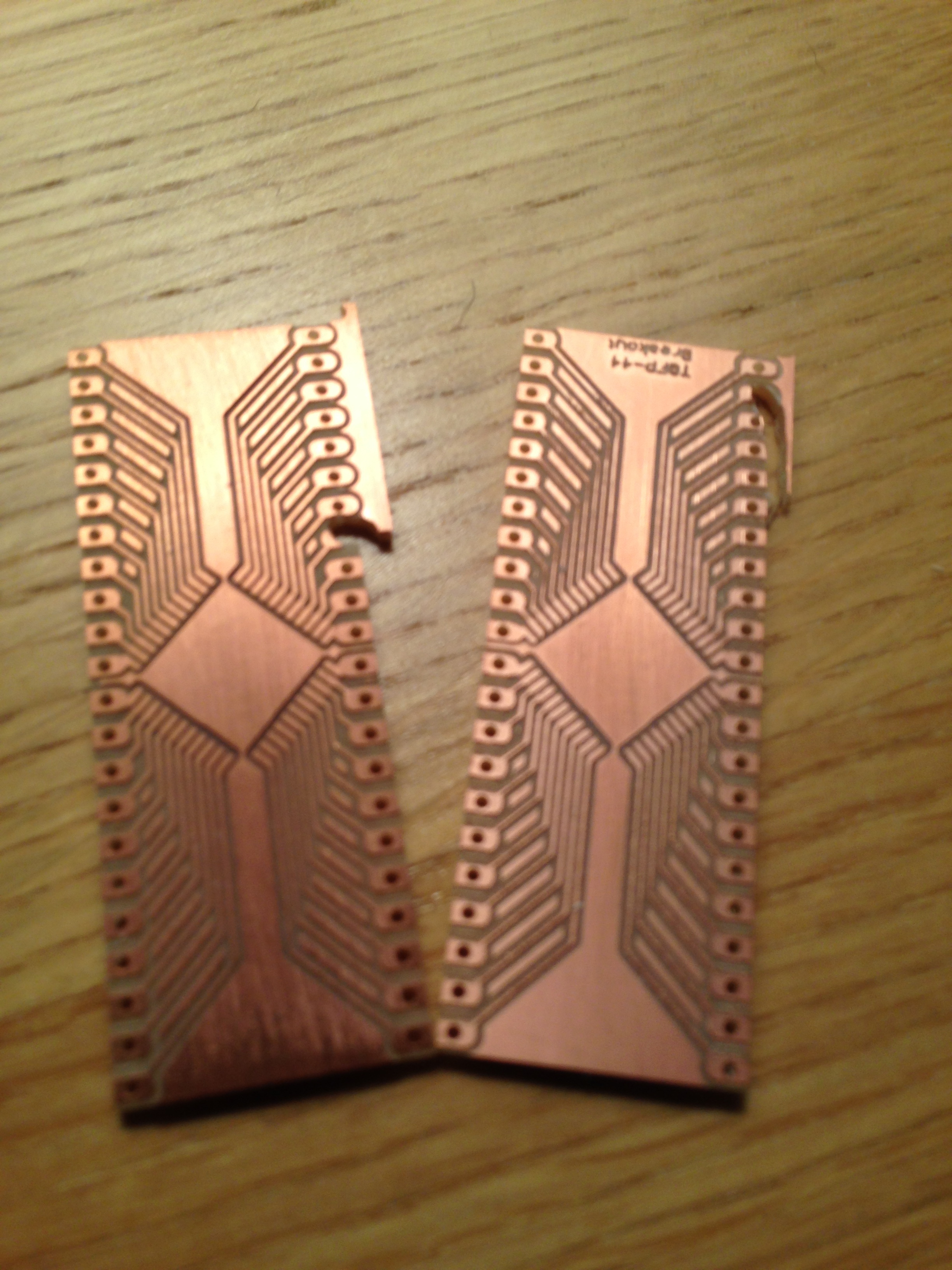
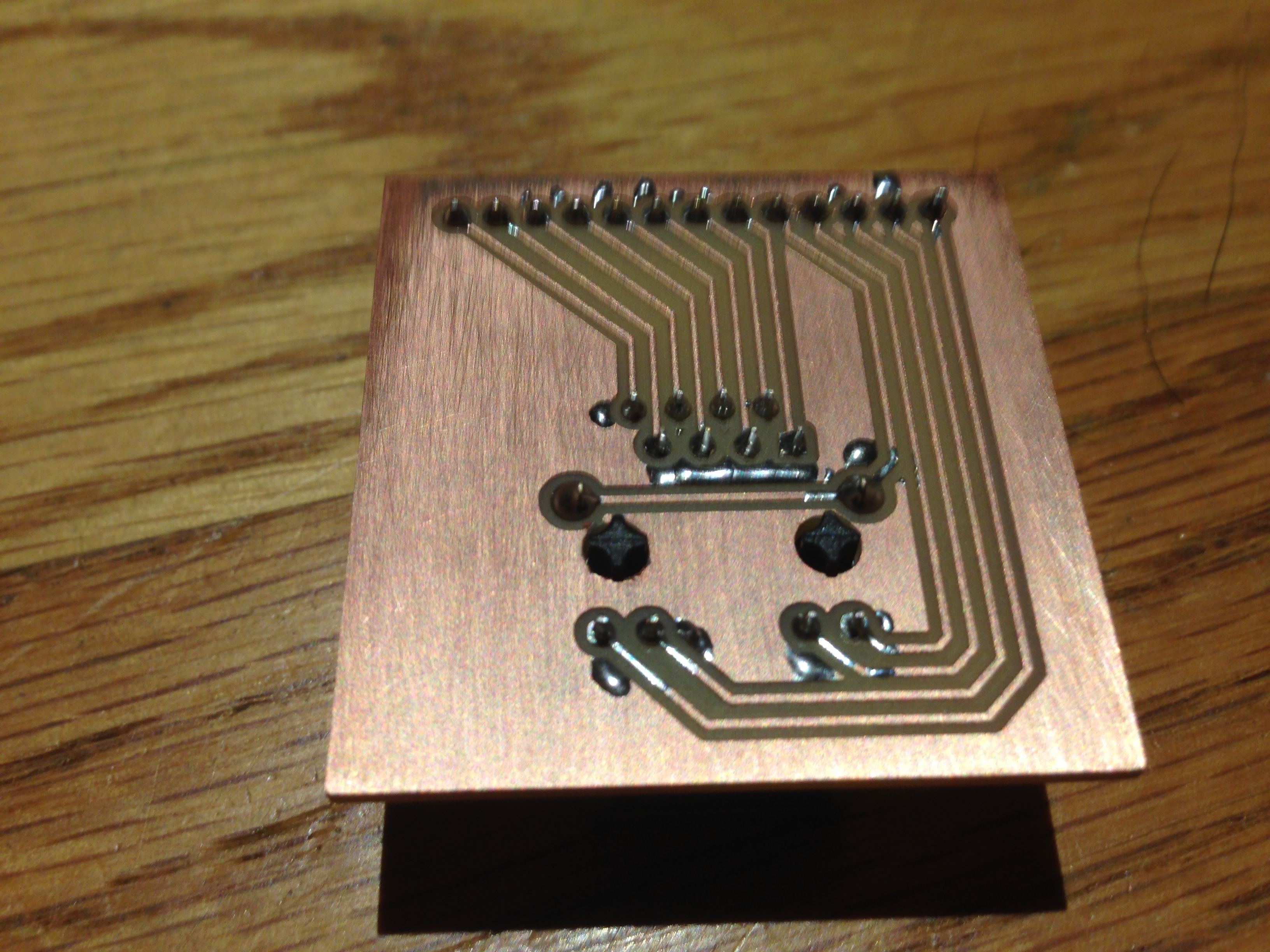
I used a 30º V-bit, EM2E8-0945-30VC from Precise Bits (http://www.precisebits.com/products/carbidebits/scoreengrave.asp) and FR1 blanks from Inventables (https://www.inventables.com/technologies/circuit-board-blanks). The FR1 are cellulose based and are supposed to produce less toxic dust than the FR4 fiber glass base blanks and are easier on tools, though I’m sure breathing FR1 dust is not without it’s risks. For drilling I picked up a set of metric PCB bits from Precise Bits (http://www.precisebits.com/products/carbidebits/drill_sets.asp) and a set from Inventables (https://www.inventables.com/technologies/pcb-drill-set). I used Eagle Cad 7.3 with pcb-gcode-3.6.2.4. The trace width on the Ethernet breakout board are 16 mils. The feed rate was 7 inch/minute. I didn’t really have trouble with keeping the PCB boards flat. The issue I ran into was keeping the PCB board anchored when milling the perimeter. I was using carpet tape to hold the boards down. I destroyed two of the TQFP-44 breakout boards when they came loose from the wasteboard.