Just finished a new build of an XXL following directions provided by Carbide 3D. I estimate it took twice as long as needed due to some issues with the directions provided/lack of labeling on packaging. I could give you a line-by-line review of difficulties experienced if it would be beneficial, but I’d rather not waste any more of my time if they are not likely to be incorporated into the manual.
Also - why is the X-Drag chain routed to the front when the natural wire path with the milled in hole in the Y-axis endplate would bring it in from the back? The picture in the assembly guide even shows that the drag chain is missing 3 covers due to the odd fit.
I installed my drag chain to the back and it fits perfectly well this way, thought the cords all enter the electronics enclosure via the front.
Some simple suggestions for the Carbide 3D team to ease installation for the rest of us who are not yet CNC masters:
Color code or label the cable ends of the wires on steppers, wires and control board to easily match and ease first-use without grinding against ends.
Show slightly wider view of belt install to see that the belt on top (with teeth facing down) is the one that continues the length of the gantry. Something that is obvious to anyone who has done this before - not to a noob like me. No single picture in the instructions shows which belt stops and which continues. Also, clarify installation to include ‘ping-pong’ method that ensures fully tightening both ends of the belt and suggested acceptable level of tension (i.e. slip no more than 1 finger under belt)
There is very little information on wiring that is not endstop related. Nothing addresses running wiring to the spindle itself.
I had no Allen Wrench or single use wrench that would fit the drag chain hardware. (otherwise, excellent tools were included.)
Add annotations/circles/highlights on the endstop photos as they are hard to decipher for a noob whose not familiar with the machine.
Several bags were not labeled, but instructions indicated they would be. Possibly include a sheet with true to life screw sizes to know which screw is which and help with ID of ‘spare parts’.
Include software instructions to setup carbide motion & grbl with endstops and larger bed size directly in the XXL instruction page.
That’s it off the top of my head, but I know there was more if I look back at my notes…
I am looking forward to testing the machine and getting cutting now that I’ve successfully completed the logo with marker!
I totally agree with you Ben. The manual says you can make it in an hour. I think I’m easily at 12hrs if not more.
Very poor instructions, plus various versions all over the place. Almost at the end I discovered that I had not put the panels in under the waste-board - some photographs of that step would have helped.
For those of us not familiar with CNC they could have marked what is XY & Z in so many places. Some of the close-up shots are good but they also should have a wider angle shot to see where the area of detail is.
I could go thru the instructions and find many issues. AFAIR nowhere does it say to mark connectors with where they are coming from, so that by the time you get to plugging into the board you have no bloody idea what is what.
If they haven’t done this already they should get someone who has never put a machine together before and have them assemble based on the instructions, with no help from Carbide 3D, and video tape the session so that they can see where things don’t make sense.
I can tell this is a well made machine and I am excited to use it but as of now it’s simply not working.
I did this when I created the original assembly instruction manual for the regular Shapeoko3, and had a woodworking friend of mine be my assembly guinea-pig. And, that was before they assembled portions of the machine for you—you were building the whole thing from loose components.
It’s now considerably outdated as the machine designs have changed a bit, but maybe some of the descriptions and illustrations in that older version of the manual may yet prove useful for you.
Mine took a couple hours using the current instructions up on the carbide web site. They’re not great, particularly the limit switch mounting, but it wasn’t -that- bad.
The assembly manual isn’t great, but I think it gets a worse rap than it deserves.
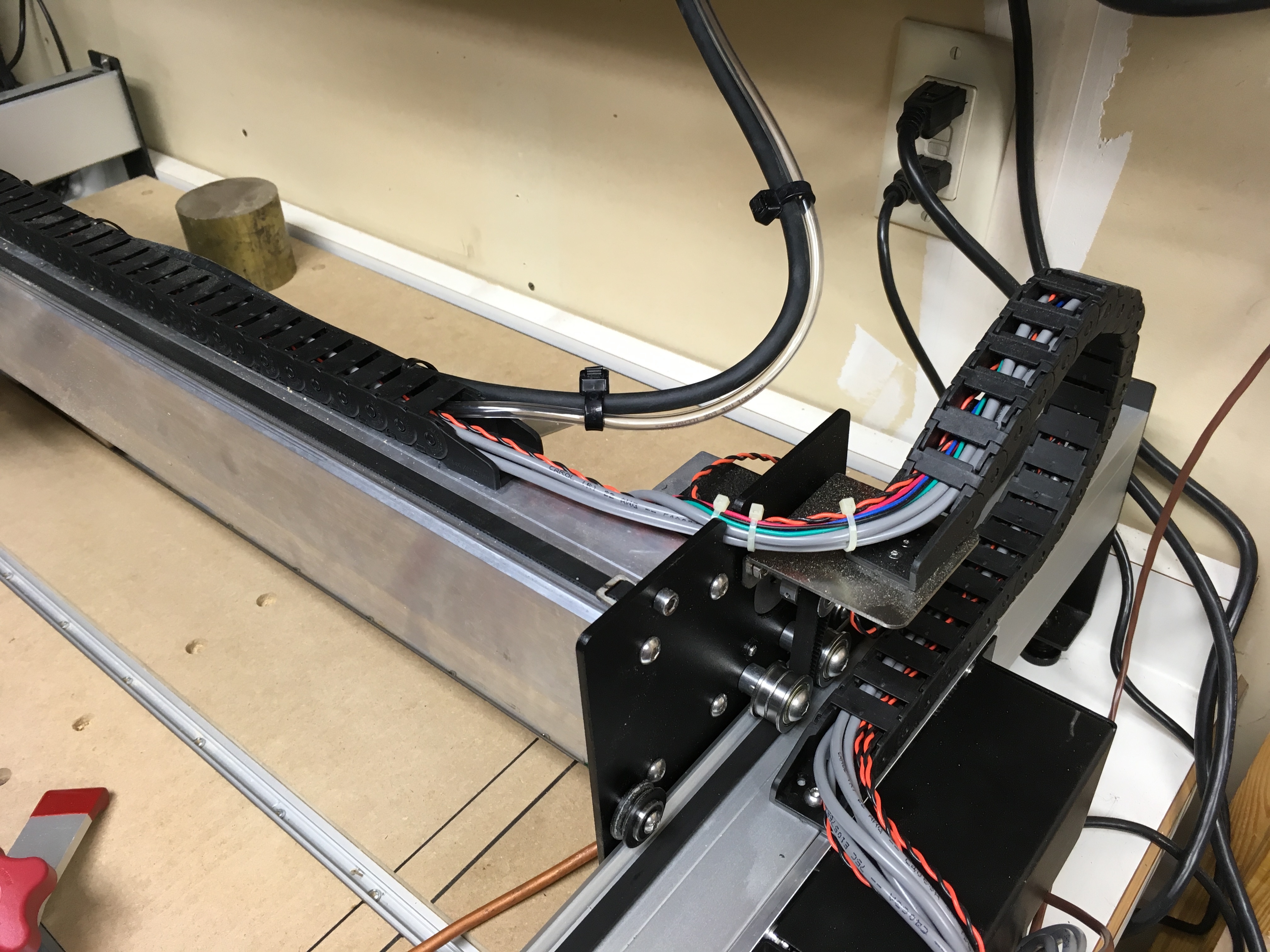
I will note that for anyone interested in reverse mounting their drag chain to the rear of the machine instead of the front (as it seems designed to attach, fit perfectly in the Y-Axis plate wire guide hole, and removes an attractive thing for kids to grab from the front of the machine, I removed 4 additional links.
The only negative I see is that the chain has a slight 2" overhang off the rear of the unit - It actually does this at the front as well, but it occupies the same space on the Y-axis that the router/spindle occupies, so technically this means the square of space required by the machine is slightly larger with the reverse mount instead of the front mount. It also has the wire mess entering the case from the front which is slightly less attractive.
Well worth it in my case.
Also, anyone know if they stopped putting the fancy ‘SHAPEOKO’ logo on the gantry or if mine was just sent without for some reason?
Mine is mounted to the back, and doesn’t overhang. Just take off a couple more links. I also mounted the controller on the right instead of the left, but that shouldn’t make a difference. In this pic, gantry isn’t all the way back, but trust me, it goes all the way back and nothing overhangs.
i’d give anything for some decent photos. for each step 2-3 images. showing before and after. maybe think about lighting a bit, black parts on black parts == very hard to see anything.
the instructions leave the user to infer a lot and to recheck and triple check these assumptions - and that slows it down considerably.
oh and +1 on the hex key for the drag chain attachments - good job i had one in the shop.