I have build my 4 XL but I am wondering about the software settings. In the configuration machine type I can pick the 4 or the 4 HDZ option. Same with the Z-Axis type, HDZ or Z-Plus. I have googled leadscrew and ballscrew but it’s not clear to me yet. It’s probably my English, I just want to be sure that I make the right selections…
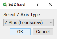
The stock Shapeoko4 comes with the “Z-plus” Z axis model, that’s the one with a leadscrew
(The “HDZ” is an add-on based on a ballscrew, that can be purchased separately)
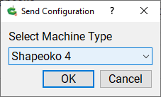
So for your new machine, in the “send configuration data” you should pick “Shapeoko4” from the list:
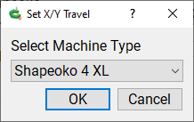
In the travel dimensions, “load defaults”’ button, you should pick Shapeoko4 XL,
Swap the connections between Y left and Y right at the controller side, this should take care of that.
Either you swapped them while connecting them, or the cables were mislabeled
EDIT: I read too fast, do you mean the gantry moves to the front rather than the back, or that the Y motors fight each other and the gantry does not move ?
The cables say Y-L and Y-R, the controlers says Y1 and Y2. The online manual says that Y1=L and Y2=R… Switching them did the job, thanks! One more issue, the Y limit switch doesn’t work. when I touch them with a metal object, they light up but it doesn’t stop when it travels to the front of the machine…
You mean the back of the machine, correct ? (towards the Y limit switch)
So the switch itself is working. Next, check if it registers:
do you see a LED light up on the controller board when you manually trigger it like that ?
in Carbide Motion, with the machine connected but not initialized, go to Settings, “Machine” tab, it has a “GRBL Active Input Pins” line, do it display “Y” when you manually trigger the switch ?
If this works and the machine still does not stop at the switch, it is likely a problem in the mechanical position of the switch. With the machine powered off, slowly move the gantry to the far back, as far as it will go, and check what is the distance between the gantry plate and the Y limit switch. Grab a picture while you are in that position
Ok, so the picture agrees with the text that YL=Y2 and YR=Y1, right ?
(your original message said Y1=YL Y2=YR?)
Anyway, looking at the video I’m now a little confused: this is the symptom of YL and YR being reversed, so I would say switch them…back, and capture a video then ?
when I switch them back, the left Y motor is turning the opposite side from the right Y
motor so I think they are ok right now… The machine however is trying to find HOME in the right front corner, then hits the endplate.
I have checked the wires, they seem ok. Let’s assume the wires are ok, it seems like the polarity (+ and -) might be wrong somehow, it is trying to find the home spot in the front-right corner. Any other suggestions?
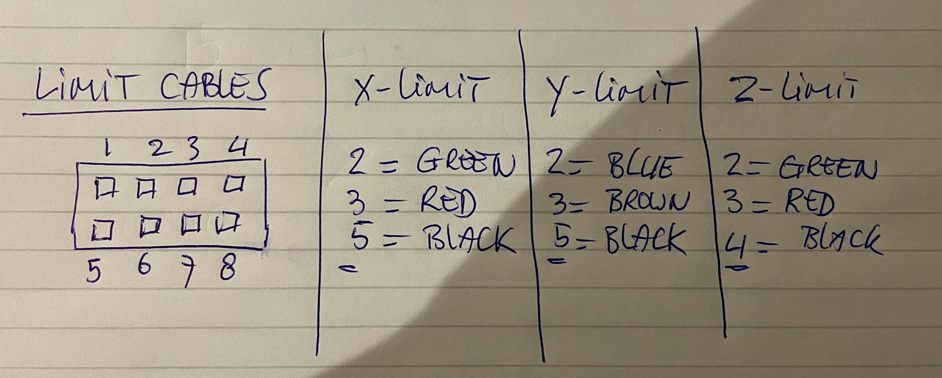
When I check the wiring (from the back of the plugs) of the limit switches it seems off as well somewhere with the black wires.
Another thing that doesn’t make sense (to me). When I take the wires from the YL-motor (see picture below) the wires go in as black - green - white - red and are connected to (same order) green - black - red - white. (so the same colours are not connected)
There are a number of ways to wire up stepper motors — some will result in the same movement despite differing order, others will result in the rotation being reversed.
The Y-axis rotation for one motor is reversed in the board circuitry, so if both are properly counter-rotating, but not in the correct direction, the easiest fix is to power down and swap the two Y-axis connectors at the controller, even if this is counter to the instructions. That will reverse the Y-axis movement and allow things to home at the back right corner.
Please let us know about this at support@carbide3d.com — even if you’re up and running, we need to know about this for QC purposes.
Thanks for your support so far. $3=5 and I changed that to 7. When I try to initialize again, I will get the situation as in video IMG 7615 (the same situation also when I swap Y1 and Y2 again).