The way I’d describe it is that GWizard will only tell you what’s safe for the spindle, but it can’t tell you what’s safe for your machine.
If the machine were more rigid, GWizard’s suggestions might be more reasonable but the 883 Pro at least was like jelly. You might have more luck with the Nomad 3 though since they’ve beefed up some of the linear motion components.
The good thing is that the stock Nomad is pretty good at not breaking itself, so even if you screw up feeds and speeds by listening to GWizard, you’ll just ruin your stock or break an endmill. The steppers and spindle aren’t powerful enough to damage anything else.
Back on topic though, max feedrate is very unlikely to be your friend. Even on my Nomadtron, I’d only go to 3600mm/min with a 4-flute endmill.
Thank you @Moded1952 for that extra helpful info, much appreciated! If I were to tell GWizard that my max feed rate was something like 1600mm/min, would I get safer values from it?
If you are really interested in learning about how to set feeds and speeds yourself from scratch, before using a calculator (any of them), I would suggest learning more about the underlying principles of milling. Even though it’s a pretty deep rabbit hole it’s also a fascinating one. There are many threads about this, and folks here who know this topic inside and out and much better than I do, but since I went through the same phase of being puzzled about why on earth GWizard would give me such a wide range of values for a given situation, I took a dive in this topic and tried to document it for the casual hobbyist here. It has a Shapeoko bias on the recommended values, so take those with a grain of salt, but I think all the principles apply as is. Spoiler alert: I have not launched GWizard since then. Not saying it’s bad, it’s just not for me and the turtle/hare slider drove me crazy.
Once you have learned about the theory, learning how to use @gmack 's feeds and speeds calculator is a good investiment of your time I think.
Sorry for chiming in, couldn’t resist, I’ll leave you guys to continue the discussion!
They’d be safer but still not necessarily good. The biggest problem IIRC (I haven’t touched GWizard in around a year and a half due to its uselessness) was that it liked high-axial, low-radial depth of cut and the Nomad 883 Pro hates that with a burning passion. What the 883 Pro liked was high radial. My understanding is that high radial is good because the cutting forces parallel to the cutting plane are substantially reduced, reducing the force pushing the endmill away from the workpiece.
Huge +1, this is a fabulous guide and I’d recommend reading it in full before you start screwing with feeds and speeds too much, otherwise you don’t really know what you’re doing (and that’s how I broke endmills).
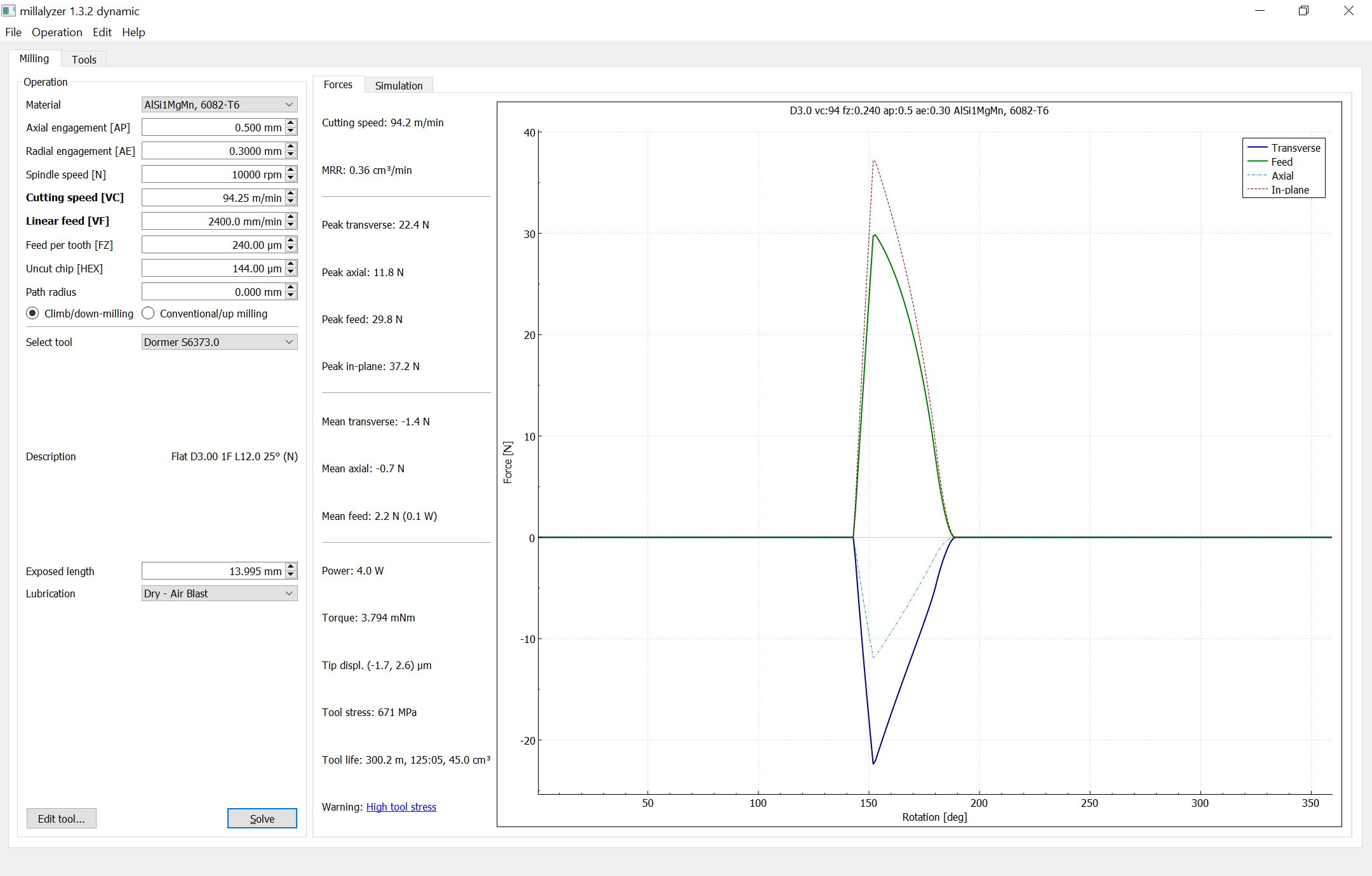
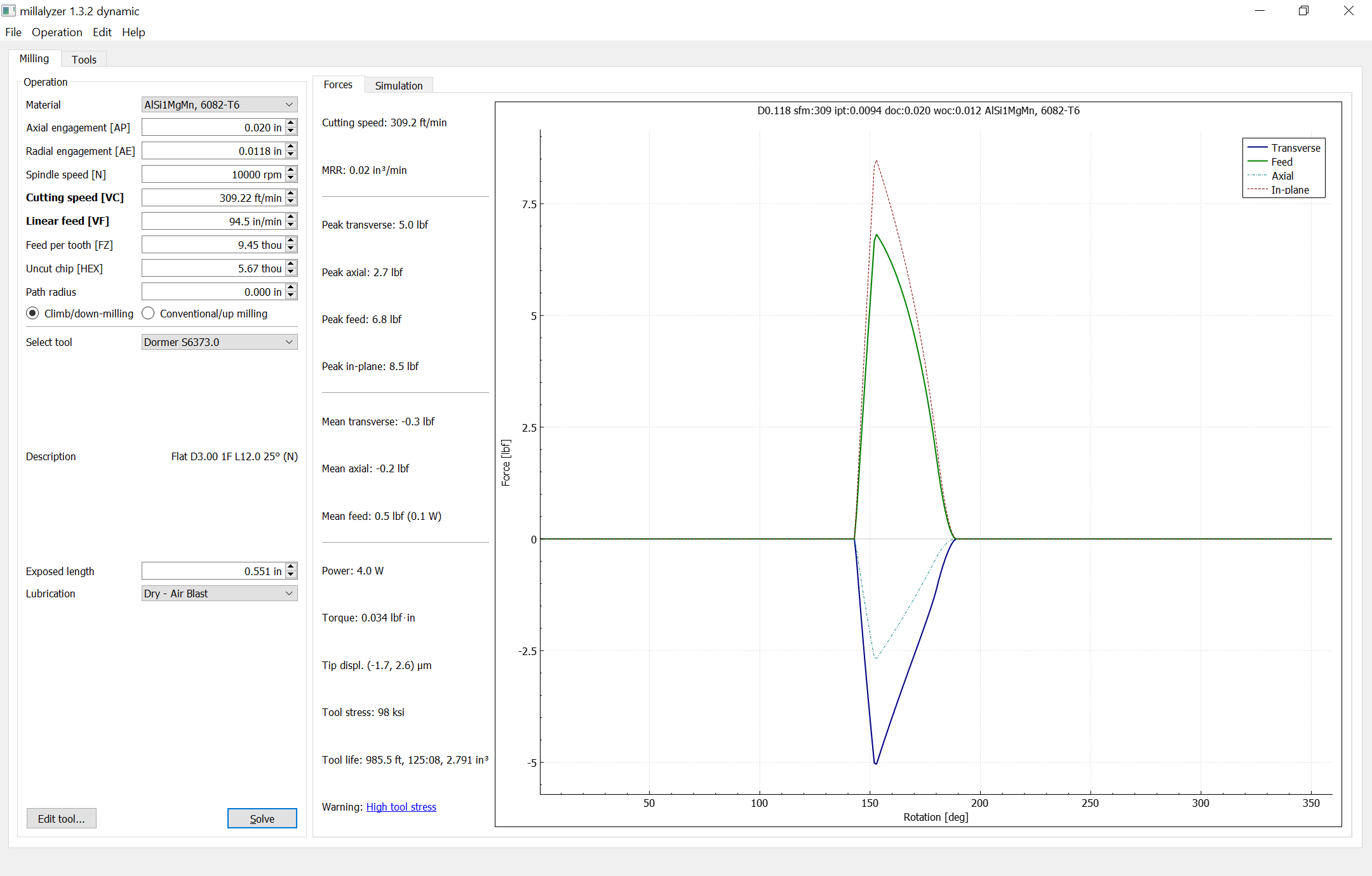
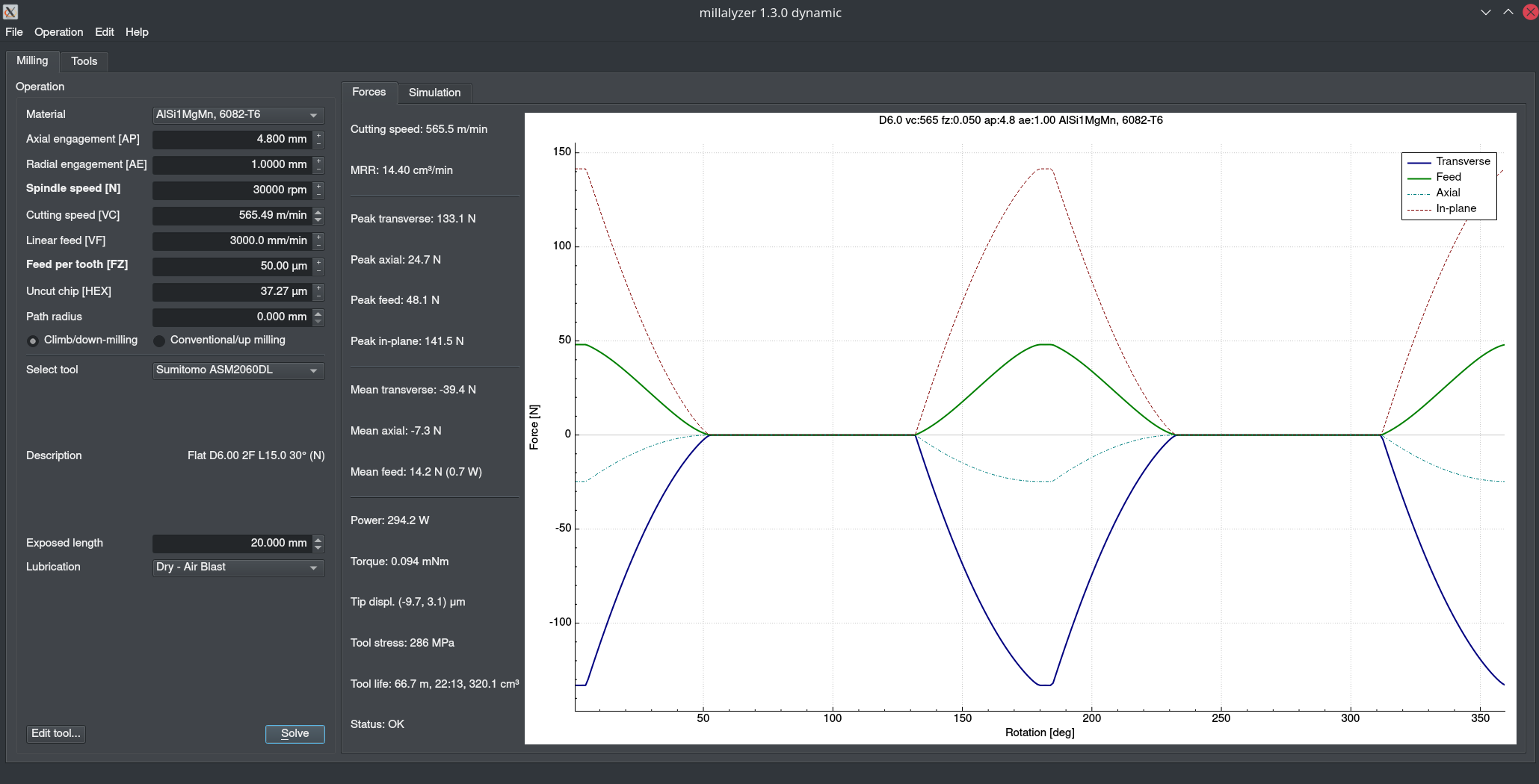
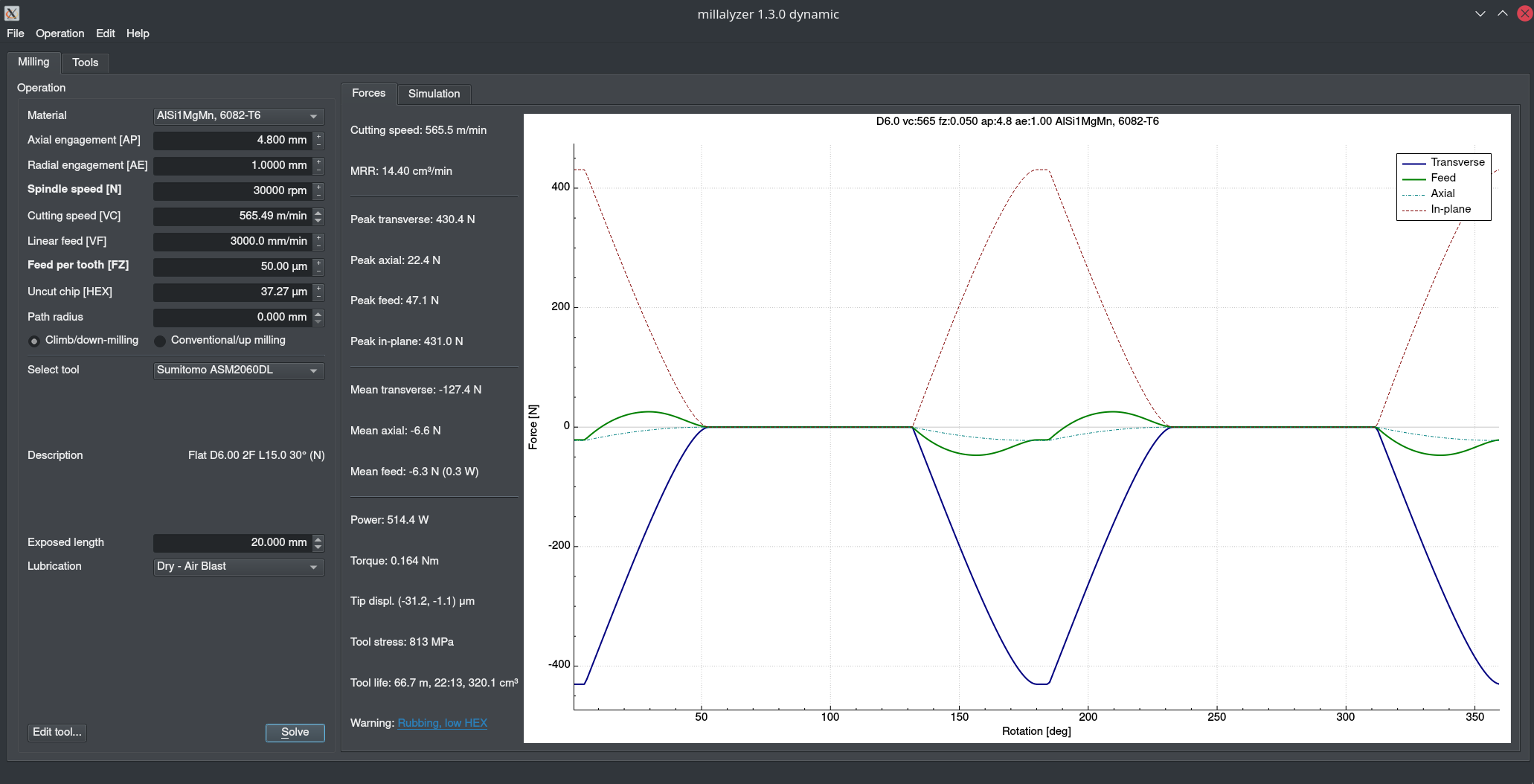
One last thing I’ll add to the thread is that Millalyzer is fantastic for analyzing feeds and speeds. I haven’t tried to use its “give me feeds and speeds for this material” mode but it’s amazing for understanding what exactly is going on in a cut.
I’ve learned a lot from hsmadvisor and it provides a fantastic starting point for me in various materials. I spend a lot of time deciding feeds and speeds for a new mill/material combination and since I don’t have any idea what values are sane, I like being able to see the ballpark wattage a given cut in a given material will take. It has enabled me to make deep & narrow adaptive cuts without being an expert machinist, and the results are fantastically better than shallow & wide on a nomad 3. Absolute game changer for a novice and it’s just a starting point IMO.
Thanks for the links, that shapeoko tutorial is golden.
My experience was that the numbers were getting into the realm of possible if you set the turtle/hare slider all the way to turtle. But where should I set the slider? I can’t go too slow, because I’ll burn or melt the material.
And even with the slider in the green (around 30-40% I think), I stalled the Nomad cutting HDPE using the GWizard settings. It was way too optimistic as to what the Nomad’s spindle can handle. Looking at my notes: HDPE, 6mm endmill, 18k, 900mm/min, slot cut with 8mm DOC. That’s an instant stall.
In the end, I realized that GWizard just doesn’t give me reliable numbers to go on. It was not a good purchase.
I am getting much better numbers from HSMadvisor. It’s not perfect: for example, I wish it took into account that you simply can’t cut acrylic with slow feed rates, or you’ll melt it. I also noticed the recommended numbers sometimes jump a lot depending on tool stickout. While that might be the case for harder materials, there are more important factors for plastics. But overall it gives me numbers that are aligned with what I’ve seen from (limited) experience.
I think you highlight a good point about these software tools, particularly with the machines we are using. You have to add a healthy dose of intuition, experience and often scepticism to their results. And maybe concentrate on the “advisor” part and take it as general advice and not strict law.
IMO, since cutting forces are reduced when spindle speeds and endmill diameters are increased as well as when chiploads are decreased, spindle speeds and endmill diameters should be maximized and chiploads minimized to the extent possible. But spindle speed should not exceed the endmill manufacturer’s limit for the material being cut. If the endmill manufacturer provides a minimum chipload for the workpiece, like Kennametal’s “Max Chip Thickness”, I’d use that. If not, @Julien’s recommended universal 0.001" chipload (actually IPT?) would be a good way to determine an appropriate starting feed rate.
In my experience it’s not that simple. On my machine it’s possible to take a 1mm axial, 4.8mm radial cut with a 6mm endmill (actually I can just about quadruple the depth I think) but not a 4mm axial, 0.5mm radial, despite the latter cut being all around lighter.
I agree on speeds and endmill diameters but not on chipload. I always stick to the manufacturer’s recommendation when it comes to chipload. You definitely shouldn’t go high (that’s how you break endmills) but as you go lower, the endmill edge has more collisions per unit work, which I’m guessing is bad for tool life and the chips are smaller, so can’t carry away heat.
Plus, as I said above, I don’t think cutting forces are the variable to optimise for.
I’d put the manufacturer’s recommendation in the calculator and then leave it to do the optimisation (e.g. account for chip thinning).
I agree if the manufacturer provides realistic minimum chiploads, like Kennametal’s 0.0059" minimum “Max Chip Thickness” independent of endmill diameter but unlike Amana’s (overly aggressive chiploads?)
It has settings for transverse, feed and plane but they don’t appear to help here.
Cut
Feed
Transverse
Plane
4.8mm radial, 1mm axial
12.1
17.6
18.3
0.5mm radial, 4mm axial
8.3
8.2
11.7
The low-radial, high-axial cut has lower forces in every respect and yet it just doesn’t work and becomes a chattery mess.
I don’t think that’s necessarily crazy, you just have to adjust the width and depth of cut to compensate. When doing adaptive toolpaths for example, I’ve pushed 3mm single-flute endmills to 2400mm/min at 10k RPM (nearly 5 thou FPT) but I did it with IIRC 0.3mm width and 0.5mm depth.
Well friction is the product of the coefficient and the force applied so yes, it should, but it also reduces the amount of heat carried away with the chip. I don’t know how those two equations balance.
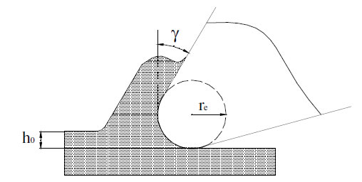
The most important aspect regarding chip thickness is that the edge is never perfectly sharp, but looks more like this:
h_0 is the chip thickness here, and in this picture it’s smaller than the tool edge radius r_e. The tool is kneading the material in front of the radius instead of shearing it off. What you want to happen is more like this:
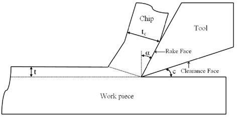
Here the uncut chip thickness (t) is much, much larger than the edge radius. I think it’s fairly intuitive that the second process is more efficient in lifting off the chip from the stock.
This doesn’t mean you should go for the largest possible chip thickness (feed), but stay well away from the edge radius. Hence the minimum chipload guidelines.
True, but it is concentrated to a very small area as well. The temperature inside the shear zone, right ahead of the edge, is often 200 degree Celsius when cutting aluminium at high vc.
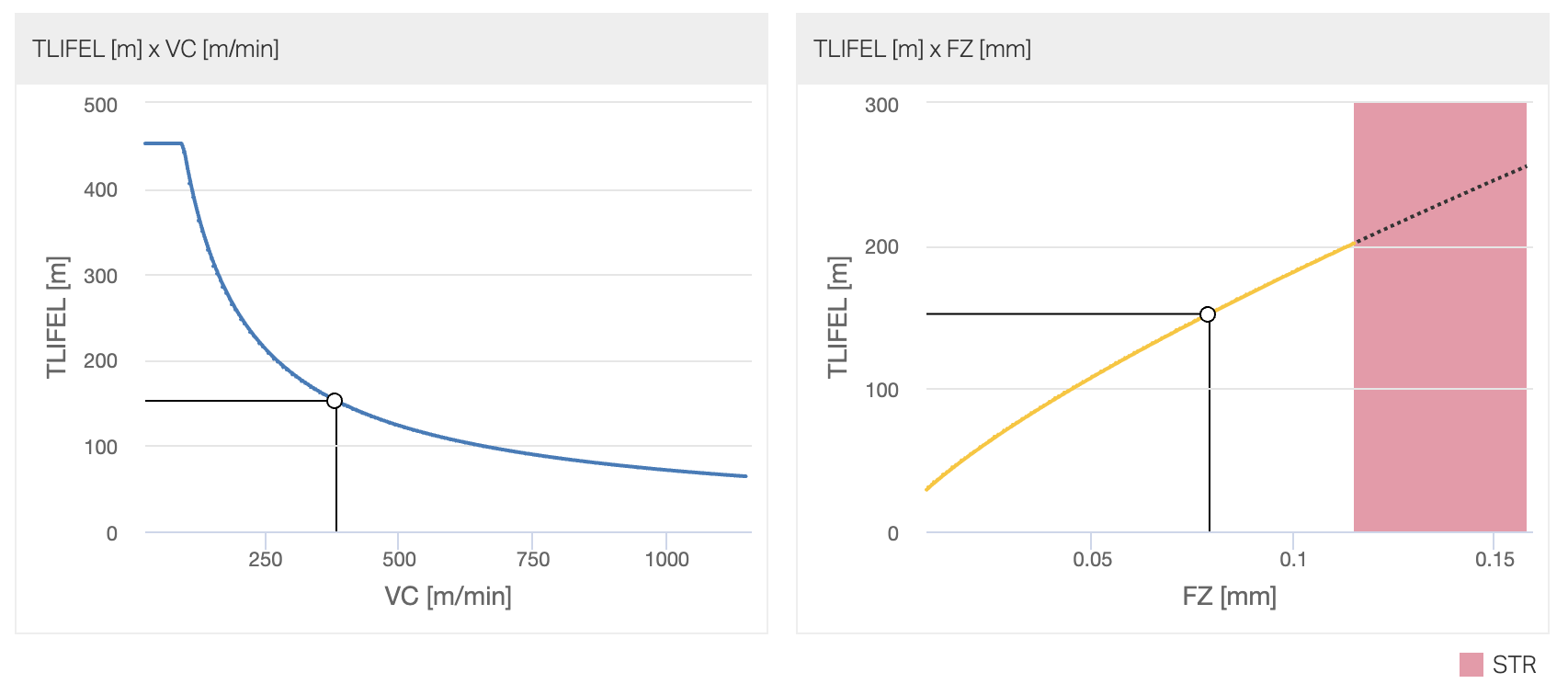
Yes, that’s about it. It’s not so much the heat itself (in aluminium at least), but the softened and very sticky aluminium sliding over the rake face. Every time it does that, it rips tiny tiny flakes out of the carbide - it’s visible if you have a decent microscope. So yes - tool life measured in meters cut usually goes up with chip-load. Here’s an example from Sandvik’s calculator:
Mind you, this is tool life in meters, or number of features produced for particular set of engagement parameters (recommended defaults for the tool). It gets more complicated if you start changing engagement as well.
How much tool life matters to you depends on how much you payed for your endmill, I guess.
Unfortunately cutter edge radius doesn’t seem to be available from manufacturers. What are typical values? Do most manufacturers likely use that or some other criteria for their minimum chipload (actually IPT?) recommendations? Can varying edge radius in Millalyzer be used to predict the impact? Is the argument that big chips help control heat valid?