Thank you both for the suggestions!
I have been running some testing over the past few days and I have come to the conclusion that the position that the inductive homing switches trips will change by up to 0.25mm on my machine as the machine warms up to a steady state operating temperature. The heat is mainly coming from the stepper motors which thermally saturate at about 35-38 C on my machine, which seems normal. The temperature swing that causes the error that I measured in the inductive switches is about 15 C (my machine is in a climate controlled garage at about 20C.) So this is about 0.016mm/C temperature coefficient observed for these sensors. I’d be curious to see the datasheet of the inductive sensor used in the nomad 3, to see how that compares. I think that there should be some amount of actual thermal drift of the position as the machine changes temperature, but it seems to be about an order of magnitude less than the changes from the switches.
I also noticed that the error changes/builds up much more rapidly on the x axis than the y axis, which makes sense because of the proximity of the stepper motor to the switch. I didn’t measure the effect on the Z axis. I think it would be similar to X.
How did I determine this?
I used a 3D touch probe that I will post about in unsupported later. It took me a while to validate the repeatability of the probe and to use it with GRBL. Ultimately, I found that I had two roll my own gcode sender and probing routines in python to be able to parse the PRB response from GRBL, which was kind of time consuming. In the end though, I have a reliable 3d probe that can do center finding of an internal or external circular feature, and it appears to be repeatable to less than 0.01mm. I will add more probing features later as needed.
I have seen elsewhere on this forum that the Nomads effective resolution shouldn’t be considered to be better than 0.025mm. However, I have found that the resolution and repeatability in controlled circumstances is actually less than 0.01mm.
The Nomad uses an 8mm lead leadscrew and the GRBL settings are about 200 steps per mm. This gives 0.005mm/step absolute max resolution. The motors appear to be plain 200 full step per revolution nema 17s. So this means Nomad uses 8 step microstepping, and I’m seeing repeatability of the about +/- 1 microstep usually for the probe, which is as good as I could hope for. I regularly see either the exact same reading repeated for repeated probes or about +/- 0.005mm (one step). For machining, the general consensus is that micro stepping isn’t super reliable, for probing though, it seems like it is to me.
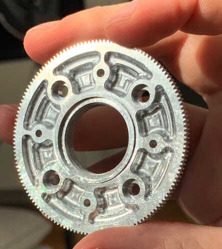
I’ll post a lot more detail about the probe and the probing routines and calibration routines that I used when I get a little further along with the probe and add a few more features. In order to generate the above conclusions I mainly used a 24 point probe calibration routine that reliably finds the center of the inner race of a ball bearing that I clamped down to the bed. My calibration ring gauge is on order.
In order to reproduce the effect that I first posted about I did the following: I ha been using the machine all day and it was fully warm. I clamped a bearing to the bed, homed the machine, and found the center of the inner race a few times, everything was repeating to 1 or 2 steps. I probed again after homing the machine and didn’t see any real shift. I left the probe in the spindle for the rest of the testing and controlled the orientation according to the prob calibration routine.
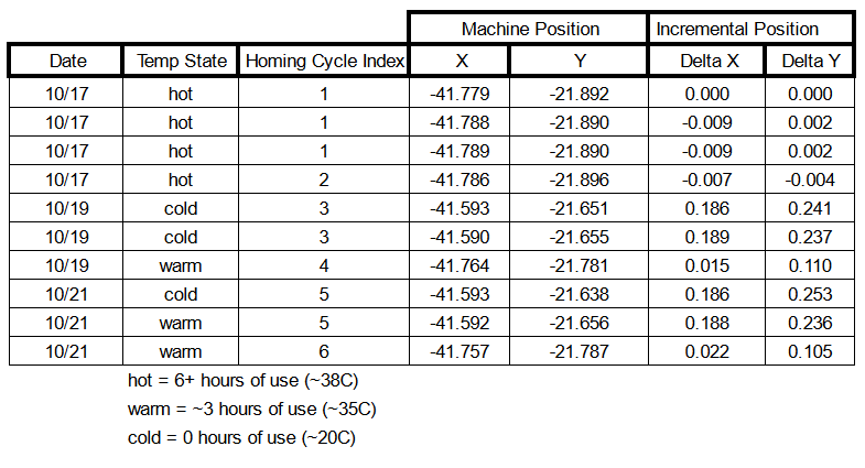
A few days later I checked again after turning the machine on from a cold state, and homing right away. The zero point shifted 0.19mm in X and 0.24mm in the Y and was repeatable again to within a step or two. Issue reproduced!
I let the machine warm up for about 3 hours (no spindle, just steppers on) and re-homed and re-checked. The X axis came back to within 0.02mm of the original reading, and the Y axis came back about halfway to 0.1mm from the original reading.
A few days later I realized I couldn’t differentiate between geometric thermal drift of the machine and thermal drift due to the sensors so I repeated the above test with a check for homing:
I turned the machine on from a cold state, homed, and checked the position of the bearing. It was the same as the last trial when I started from cold within a few steps, meaning it was about 0.19mm on X and 0.25mm on Y from when the machine was at steady state.
I let the machine warm up for about 3 hours again and re-probed without homing the machine this time and the zero had not shifted more than 2 or 3 steps. (no thermal drift observed without homing!)
Immediately after this, I homed the machine and re-probed again, and saw the offsets I saw the day before come back instantly, to within 2 steps. All of the drift is due to the sensors.
As far as I can tell, a tried and true limit switch would probably do better than this and be less sensitive to temperature. The machine itself seems to be resolving to about 1 or 2 steps, absolute worst I agree that you shouldn’t count on better than about 1 full step or 8 microsteps for machining purposes. To have your homing switches introduce an error that builds up steadily from the time you turn the machine on over the course of a few hours to reliably be 50 steps, or 10x worse, seems like kind of a bummer. I’ll be looking into whether or not I can retrofit with regular limit switches.
Looking forward to the discussion, here is the raw data: