Ok, as promised, here’s the how to. Could probably use a little editing, but it hits all the high spots.
-----How to upgrade the spindle motor for the Carbide3D Nomad 883 Pro to 70 Watts -----
Keep in mind that you are modifying a potentially dangerous
piece of equipment with spinning sharp things. Your mother would be very
upset if you hurt yourself. Stay safe.
This most certainly will void your warranty.
If you are expecting a night and day difference doing this upgrade you
will be disappointed. It makes a difference, it does not make a huge
difference.
You lose some Z travel doing this modification using the standard
Nomad 883 Pro enclosure. If you are using a different enclosure you may not
need to reduce the Z travel. The work envelope doesn’t necessarily change,
but may mean you need to use shorter tools for work near the limit.
This is how I did this process on my 883 Pro. Carbide3D is always making
updates and improvements in their products, and the material here may not be
accurate for newer or older machines.
Tools required
2.5mm hex wrench/driver, at least 3 inches long. T-Handles are not recommended.
1.5mm hex driver
A large flat bladed screwdriver
Hobby knife. Not a utility knife.
A soldering iron
Materials Required
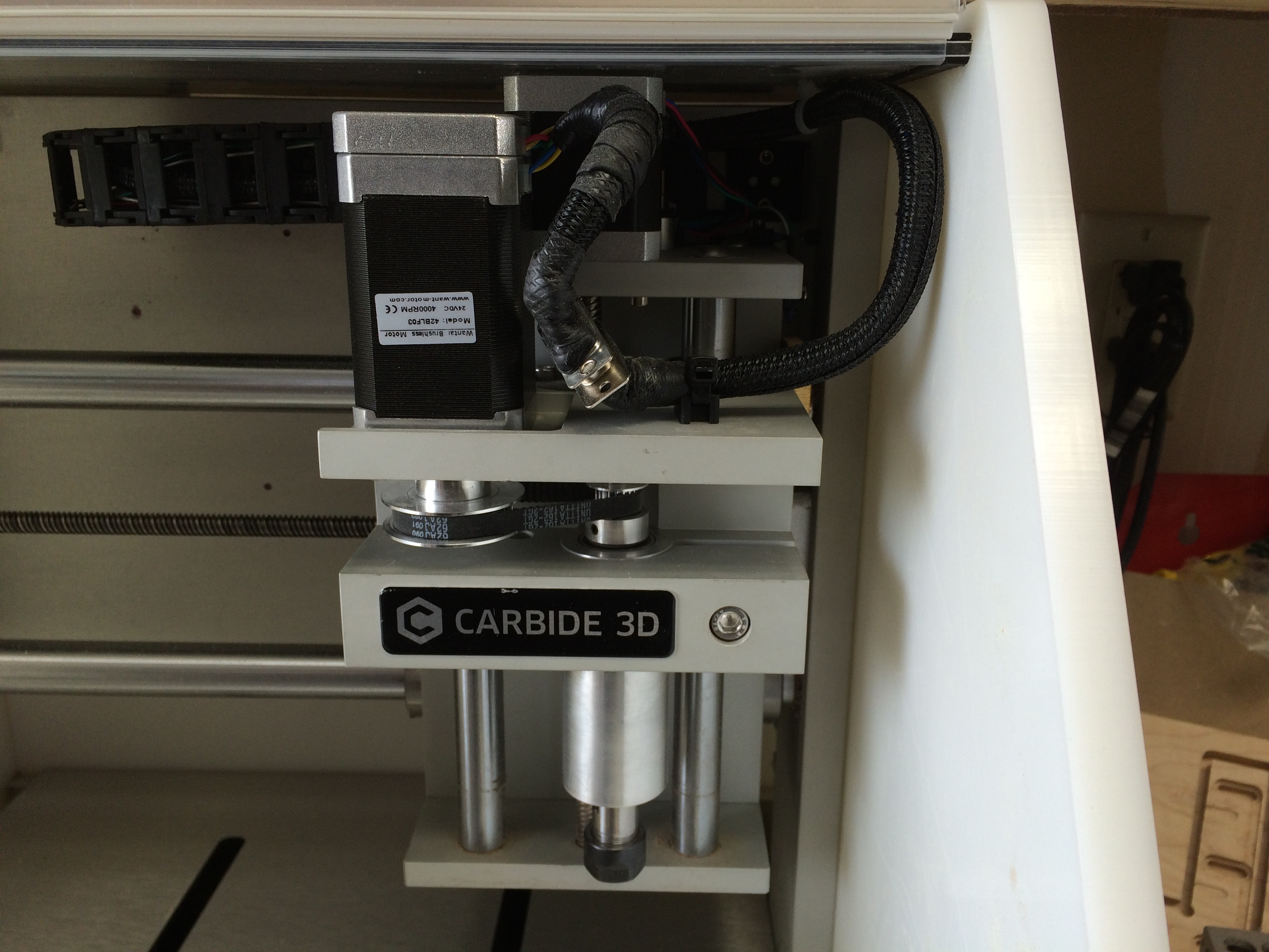
1 Wantai Brushless Motor, model 42BLF03. (Find on ebay for about $30 plus shipping)
This motor is rated for 70 watts vs the 50 of the original. The 42BL motors
match the stock motor mounting holes. This motor is however 16mm longer (79mm)
than the stock motor. The driver IC should be able to handle this with no
issues, and there is plenty of power available from the PSU.
16mm ~ 0.63 inches
You should consider the higher powered motor as a consumable item as it most
certainly does not have the higher quality bearings that Carbide3D specifies
for the original motor.
Solder
Loctite - Medium.
M+F connector of choice. I used a solder cup style DB-9 without backshell. It
isn’t strictly necessary to use a connector, but I did.
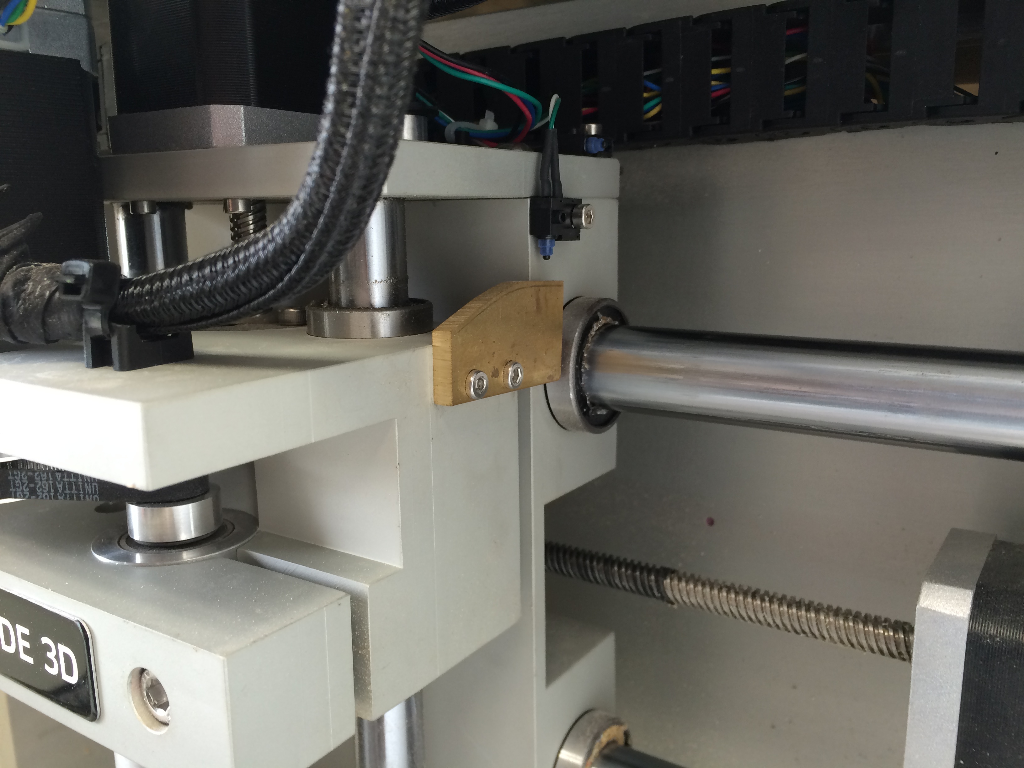
A piece of ~1/8" thick brass or aluminum material to make a new limit stop. Use
what you have at hand, but it should be at least as thick as the existing stop.
----------------------------- How to ----------------------------------------
Remove the power plug from the wall and disconnect the USB cable. Both. Really.
The controller board will stay powered if the USB cable is plugged into
a PC, even if the main power is turned off. You can damage the pins on the
controller or the wiring if your soldering iron is grounded (which is
the normal way they are built) and the controller is powered on.
If you are using the standard Nomad Pro enclosure or a replacement without
additional height above the carriage you need to make a new limit stop:
Remove the limit stop from the right side of the Z-carriage with the 2.5mm hex
driver. Use this as a pattern to make a new one that is at least 17mm taller.
Install your new stop. Push the Z axis all the way to the top, and be sure the
new stop engages the limit switch. Do not carelessly slam the Z carriage up into
the switch while fitting and sizing or you will break the switch internally.
Hold the new motor next to the old one and be sure it clears the top of the
enclosure. If it does not note the additional space you need and make a
new stop. This is a pretty easy part to make so just do it by hand.
If you can’t make this part by hand…you probably shouldn’t be
trying this process. You could also just drill and tap new holes for the
existing stop, but it’s very inconvenient to do so accurately without a lot
of disassembly. Seriously: Do not carelessly slam the Z carriage up into the
switch while fitting and sizing or you will break the switch and it is not
obviously broken.
Use the 2.5mm hex driver to loosen the 4 cap screws that hold the motor to
the carriage. The back two can be easily accessed through two holes
in the underside of the Z carriage. The motor should be easy to move a few mm
closer to the spindle which makes the belt easy to remove.
Remove the belt from the pulleys and carriage.
Use the 1.5mm hex driver to back off the set screw from the large pulley. It’s
way down in there and may not be visible. You don’t need to remove the set
screw, you just need to back it off 5 or 6 turns. If you remove it you will
drop it. Its easy to lose and really tiny.
Use the large flat bladed screwdriver to lever off the big pulley from the motor.
If you’re smart you’ll put a (metal) putty knife between the shaft of the
screwdriver and the underside of the motor mount on the carriage so you
don’t leave a mark like I did. This should take a little effort but if it’s
LOTS of effort check the set screw again, think about what you are doing,
and don’t break or bend anything.
Remove the 4 cap screws you loosened earlier that hold the motor to the
mount with the 2.5mm driver.
VERY CAREFULLY and SLOWLY, with multiple shallow cuts, cut through the heat
shrink at the end of the cable cover braid lengthwise. Do not use a utility
knife for this task. The shrink tube is adhered to the braid. Be VERY careful
not to cut the wires or insulation. Peel the heat shrink off the end of the
chafe braid.
Peel back the chafe braid. It will just unwind from around the wire bundle.
You can now cut the wires about 1.5" or so from the motor. This leaves enough
to put a connector onto the old motor so you can put it back in if you need to.
Prepare the new motor. My motor did not have a flat on the shaft to accommodate
the set screw, so I added one with a file. The shaft material is pretty soft.
The original motor has a flat. If you make the flat too deep the set screw
will be overdriven and get jammed between the inside of the pulley and the shaft
which is “a problem.” You don’t need a deep flat, just enough for the set screw
to catch. The flat on the original motor shaft is much deeper than necessary.
Wire the motor, matching the wires. Be sure to match the group of 5 wires to
the group of 5 wires and the group of 3 to the group of 3. The group of
5 is the hall sensor assembly, and has colors that are the same as those in the
phases. These wires are not interchangeable. If you want to use a connector,
do that. A simple 9 pin DB-9 works fine, but many different connectors will
work. The wire is 26 gauge, so be sure the connector/pin you
choose can support wire this small. I -strongly- recommend you do not use
automotive type butt connectors. If you use a DB-9, pot the back of the
connector with hot glue to help with vibration/fatigue. If you need to do so,
hot glue is easier to remove than silicone. There really isn’t room for a
normal DB-9 backshell.
Be careful that you leave enough slack so that the cable doesn’t bind or pull
hard against the geometry of the carriage anywhere. Any solder connections
should be between the cable-tie clip and the motor. Do not solder anywhere that
will flex later.
Install the motor and tension the belt
- Place the motor into the carriage without any screws.
- Put the pulley back on, aligning the set screw with the flat in the shaft.
- Align the pulley vertically with the small pulley on the spindle
- Loosely install the motor with the cap screws. This is a little fussy.
Don’t apply loctite at this time. - Put the belt back on, and use it as a reference to adjust any pulley
misalignment. - Reinstall the set screw on the big pulley. It should be firmly tightened,
but not “Gorilla Tight” - Push gently on the motor away from the spindle cartridge to apply tension
to the belt. Tighten the motor mount screws. Light belt tension is
sufficient. - Remove one motor mount screw at a time, apply Loctite to each screw and
replace them. - Check your wiring carefully one more time. Check for “whiskers” between the
connections, shorts, melted wire insulation, etc.
Plug it in, fire it up, start the spindle. If it makes noise, the tension is
too high on the belt, so back off the screws and try again. If the motor
doesn’t rotate, check the wiring, check that the wires are firmly connected.
Run the spindle at high and low speeds (S10000 M3 - start spindle at 10k rpm,
M5 stop spindle)
I recommend wrapping the connector area with silicone tape (“Rescue
Tape”) to seal it from swarf and other material that might be kicked up.
Electrical tape is not a good substitute in this case. Then cover as much as
you can with the chafe shield you unwrapped at the beginning of the process.
If you cut off the zip-tie earlier reinstall a new one now. Do not operate
without that zip-tie in place, or the wires will fatigue and break off at
the connectors or internally at the motor over time. Be sure to leave enough
slack so that Z travel doesn’t pull the cables hard against an edge.
This is how I did this modification. It might or might not work for you
and you might have better ways to accomplish the same end. This worked for
me and I’m happy with the result.