It’s likely a combination of factors, candidates including;
Poor power efficiency in the spindle motor losing you somewhere up to 40% of the electrical input power
Vibration in the spindle and carriage causing friction forces in the cut to build up substantially (spargeltarzan knows a lot more about this sort of thing)
Deflection and vibration in the spindle carriage allowing the high axial engagement cut to both increase in radial engagement and also oscillate in radial engagement along the line of cut and across in width of cut
Differences in the expected friction and cutter geometry affecting the K factor you actually experience in the cut (again gmack and spargeltarzan)
So it’s not likely to be one single issue but rather a series of smaller issues.
Once you get into the “measuring deflection and backlash” game you find out that even deciding which two things to measure between and how is hard, let alone pinning down all the sources…
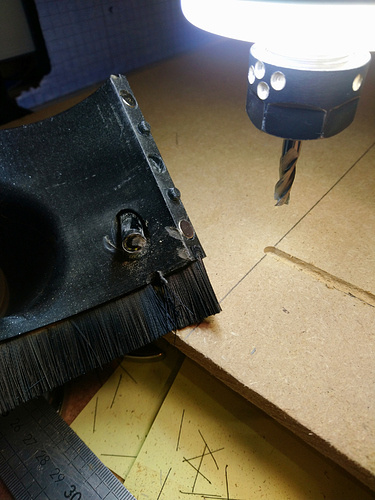
Since the endmill broke at only AP 1.0 mm and AE 0.6 mm, there’s definitely something wrong here. Of course, @LiamN is right about the efficiency (controller times motor times belt drive), but as you say, I doubt that explains a factor 3x or 5x.
Because it broke, I’m assuming it was a 3 or 4 mm endmill, so 0.1 mm (2-flute) or even 0.2 mm (1-flute) that you get for VF 2600 mm/min at 10k is definitely way too much. I get 640 MPa tool stress and 24 W for that case; the stress is in the range where I would say it might break with some chatter.
On the other hand, if that was a 6 mm endmill (which nets us 0.078 mm chips 2F, bit much but not a disaster), then I really cannot see how it can possibly break with that little cut. BUE maybe? How do the edges on the broken-off part look like?
In personal experience with the Nomad, after giving it 10x the stock spindle power and 3x rpm, it was still very much motion rigidity limited.
Then the X/Y where converted to ballscrews, cuts were much better but the remaining AB Z nut was still the limiting factor. When Z was converted to ballscrew, performance was increased in all types of cuts.
I really think the best bet would be to get @wmoy to run you some test cuts on the new Nomad 3.
Sorry, yeah, it was a 1/8" single-flute endmill. The calculator put it at somewhere around 540MPa. I was abusing the heck out of it so I’m not surprised it broke.
The main thing I wanted to prove though was that the spindle can output 70W, which apparently is the case, it just doesn’t produce 70W of MRR.
Are there any cuts or is there any data that might be useful? I have a variety of 6mm endmills to play with if you want to see what happens when it doesn’t break.
Did you ever use the Z-axis with the ballscrew but without the linear rails? The AB nut should only be responsible for axial loads, so shouldn’t have a huge impact on deflection. I suspect the linear rails on your Z-axis might be the bigger improvement?
Carbide 3D put linear rails there as well, so I think they might agree.
I am really curious to hear what difference Carbide 3D’s changes have made but my experience with the 883 Pro has made me pretty pessimistic, so it’s hard to have much hope.
Even if it is a big improvement, it doesn’t do me a whole lot of good, I don’t have a Nomad 3, I have a Nomad 883 Pro
I see. But at this large chip volume (0.2 mm chip thickness for a 3.2 mm tool diameter), it is not likely that the tool was still cutting as it is designed to do. Cutting forces could well be far higher than predicted because the most basic assumptions are violated in this case (there probably is a “chip space” warning for this condition as well).
Anyway, for your spindle power investigation, I would try a radial engagement of 80 - 90% of diameter, feed-per-tooth in the manufacturer recommended range (or DC/(100 * NOF) if you don’t have any data). Then gradually increase AP and monitor power. I know, it’s easier to increase feed.
Low AP, high AE is useful for this case because the cutting conditions change less with tool deflection, i.e. your results should be more representative of the spindle/motor performance. It appears this is what you are trying to isolate?
Regarding diameter, you wrote earlier that 6 mm tools have much more minimum stickout in the Nomad. It may therefore be better to try a 3 mm, 1/8" or 4 mm endmill if you can run that with just the flutes +1 mm sticking out. Not so much because of the deformation of the tool itself, but to reduce the lever arm, given your earlier stiffness measurements and how the Nomad is designed.
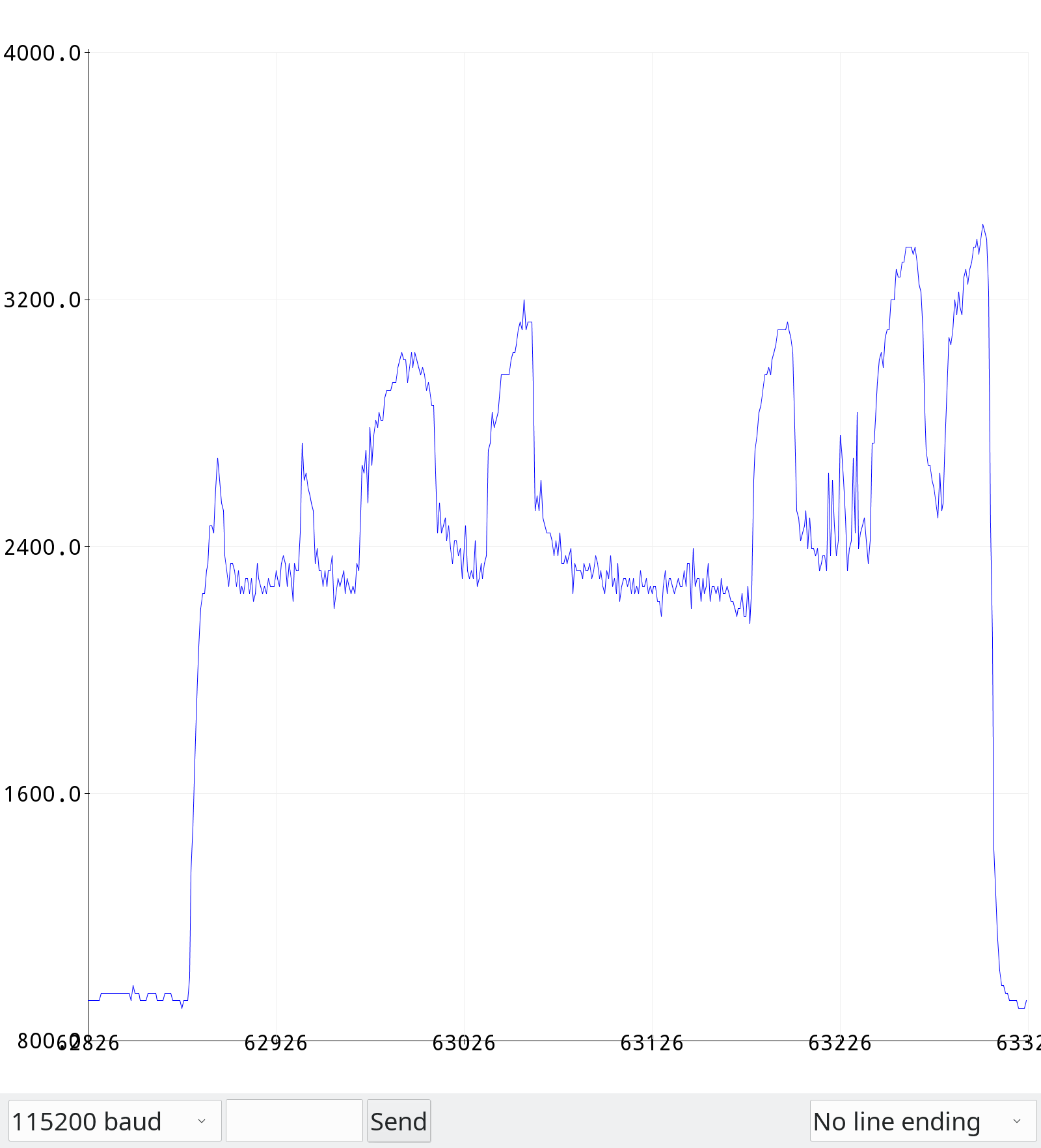
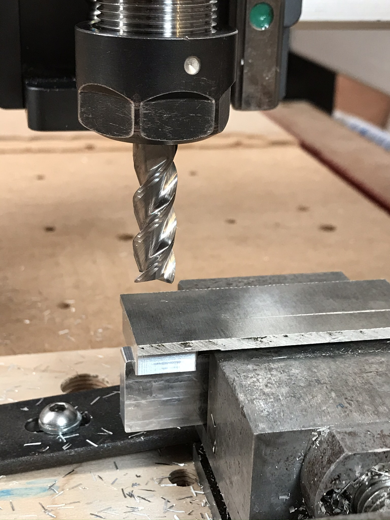
Okay, so I tried a 3mm 1-flute endmill with an 8mm cutting length and ~9mm of total stickout. I used a feedrate of 250mm/min, corresponding to the manufacturer’s recommended feed per tooth for wrought Aluminium alloys (however I can’t come close to the manufacturer’s 500m/min surface speed recommendation). I used a 2.7mm radial engagement and climb milling.
I stepped axial engagement by 0.1mm at a time and got down to 1.2mm axial before it drew ~3A. Here’s what the current draw looked like:
And here’s what that cut sounded like (of course, from outside my enclosure).
I think the reason for the odd peaks is that my stock is inconsistently faced but it’s hard to say. I think I’ll try facing it again and more consistently later and see if that makes a difference.
I should also note that the spindle consumes ~1A (24W) even with no load applied.
And Millalyzer thinks that this cut should take 14W, so we’re still dealing with a ~4x discrepancy.
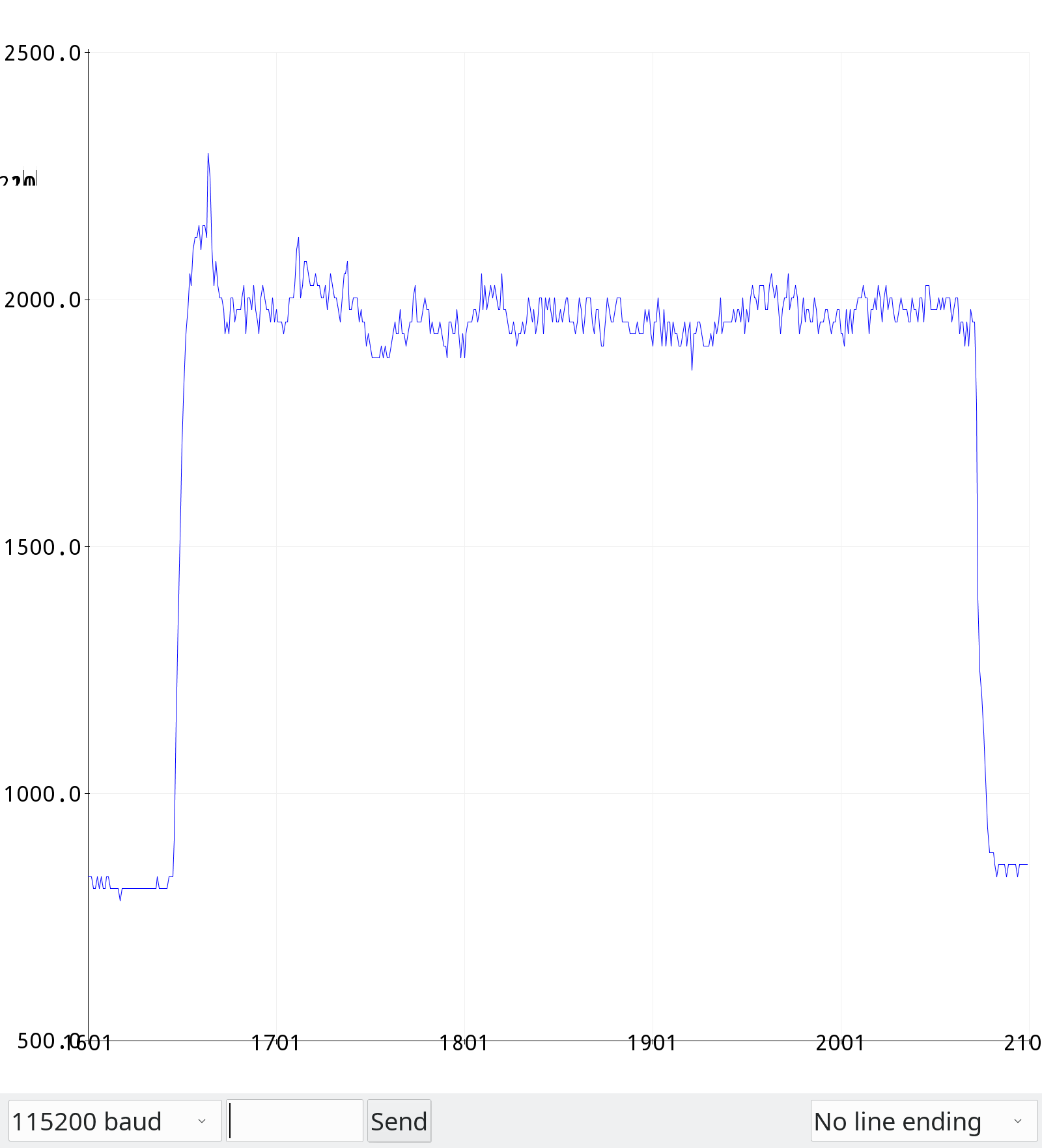
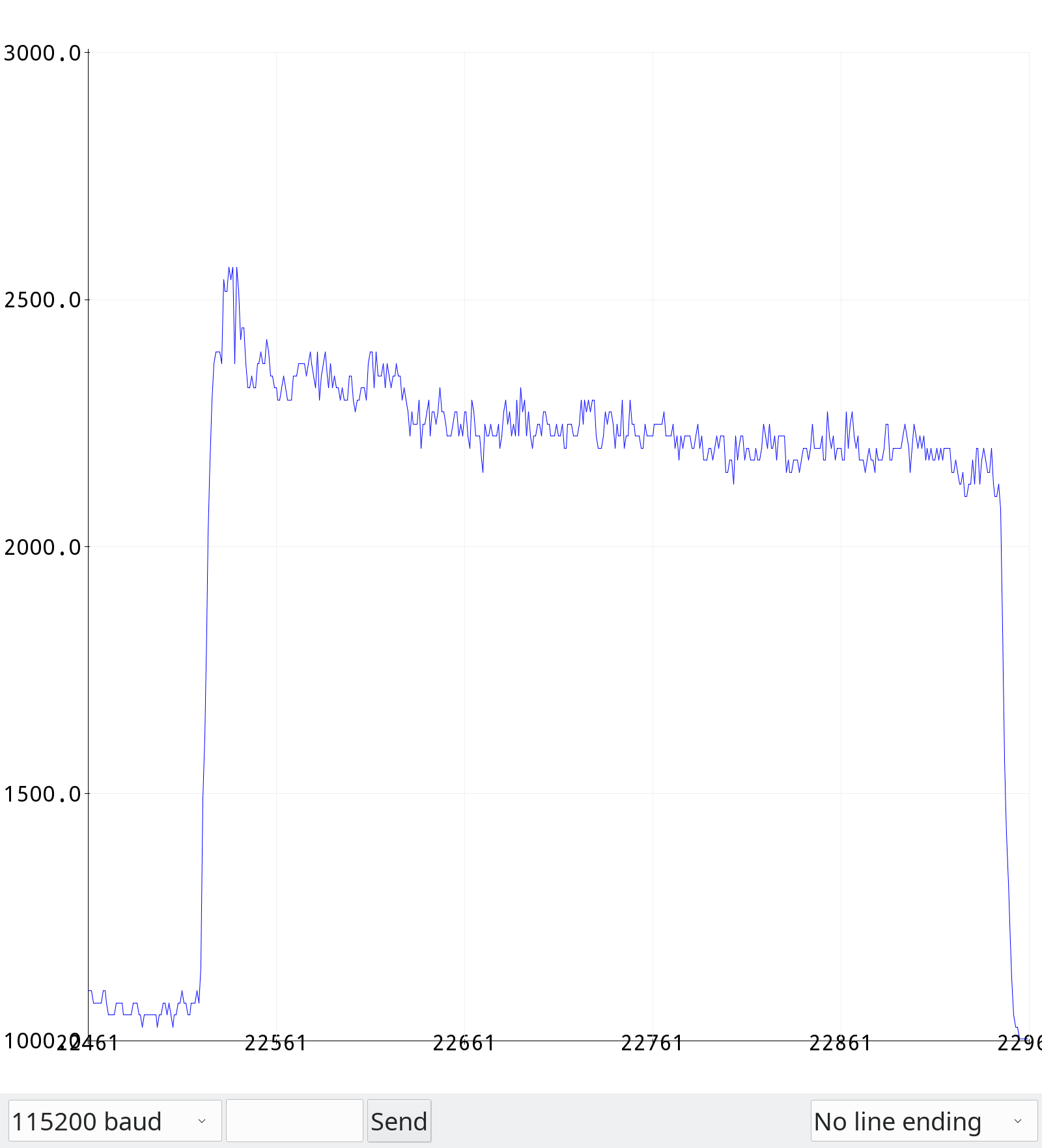
Okay, did it again after surfacing. It wasn’t actually that my facing was wrong, it was that the stock had been lifted up out of the vise at some point.
The problem now seems to be the vise. I always see after the cuts that look like this that the stock has been lifted a little bit out of the vise.
Are those sounds I hear (particularly the brief high-pitched squeals) chatter or something else? Is it the vibrations that are letting the stock slip out of the vise or the axial cutting forces?
In those videos there looks to be some pretty large vibration going on, the whole base of the machine seems to be vibrating, vice, workpiece and all, I can see the chips dancing and falling down the slot like pennies in an old arcade machine.
(the 1.5mm link doesn’t seem to work but the 1.4 was enough…)
The spindle is slowing down during the cut but this motor doesn’t have any speed feedback to the controller does it? If not then that’s entirely expected for it to drop from the no-load speed.
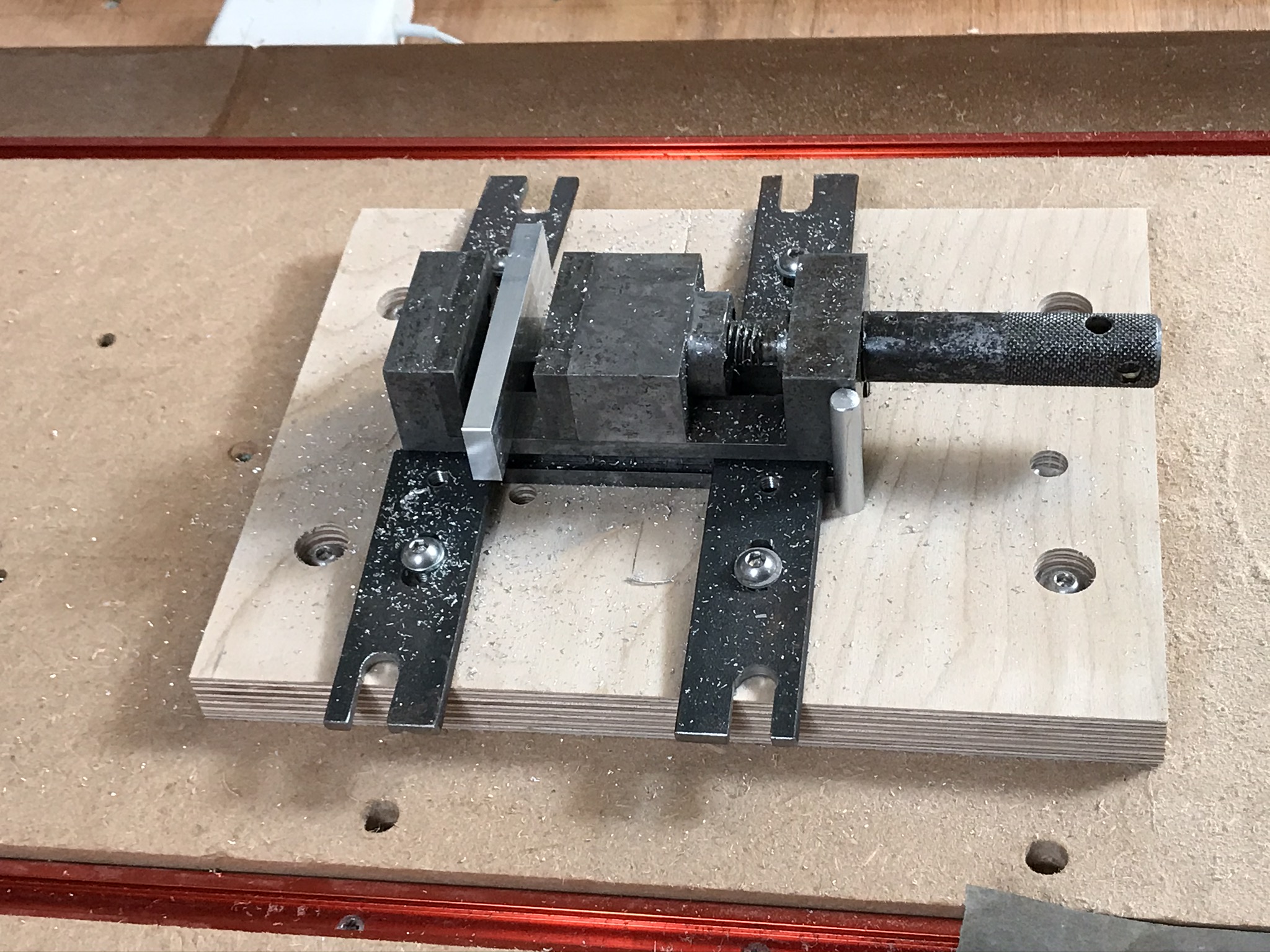
On my Shapeoko I’ve had to use a small machine vice for some small parts;
Despite being a relatively heavy bit of steel the vice just isn’t big or heavy enough, or well enough attached to be rigid with the baseboard. I get way more vibration on parts in this vice than those I just tape and glue to the baseboard and can’t go anywhere near as fast before the bad noises start.
Are you using the ‘normal’ Nomad vice and workholding for this?
Maybe you could try grabbing a chunk of heavy steel plate and using that as a mounting plate for the vice to reduce some of that movement with some extra mass and rigidity?
Folks like vince.fab have presumably got some experience with workholding on the Nomad and how to minimise the vibration?
Yep, that’s definitely the case. It’s quite loud too, even with the enclosure that makes lighter cuts near-silent.
Sorry, should be fixed.
No, not that I’m aware of. There are only 3 wires going back to the McGillicutty so I think it can be doing that.
You mean it’s expected for the speed to drop?
Yep, the Carbide 3D precision vise, though that’s attached to a heavy chunk of Aluminium with T-slots cut into it. I can try attaching the vise directly to the Nomad’s bed as well but I fear that will make things worse.
I also have a bunch of T-slot clamps, do you think it’d be worth trying those out?
I think the Aluminium bed I’m using is already quite heavy so it should have the same effect.
I suspect what I really need to do is just get a better vise.
Or it could be, as Vince suggests, that the anti-backlash nuts are too weak. No matter what I do to the bed, if the nut isn’t properly rigid, there’s going to be vibration.
There are clearly multiple sources of deflection and vibration in the machine. Which of them to fix in which order for the greatest benefit is the million dollar question. Given the number of mods Vince has made and his quality of work output, I’d give his suggestions a significant weighting in my decision process about what to upgrade to get the desired performance.
I’ve spent a fair amount of time measuring relative movement of parts of my XXL with a dial gauge on a mount. That has really helped understand what is deflecting but it’s also given me a baseline to do really rapid checks of whether the machine is “normal” or something is getting loose. I know the collet slack and deflection I expect for 5kg force at the collet in X and Y so I can very quickly check if things are OK.
From what he’s said, the ballscrews seem to be among the most impactful, though I think the linear rails on Z are a big deal too.
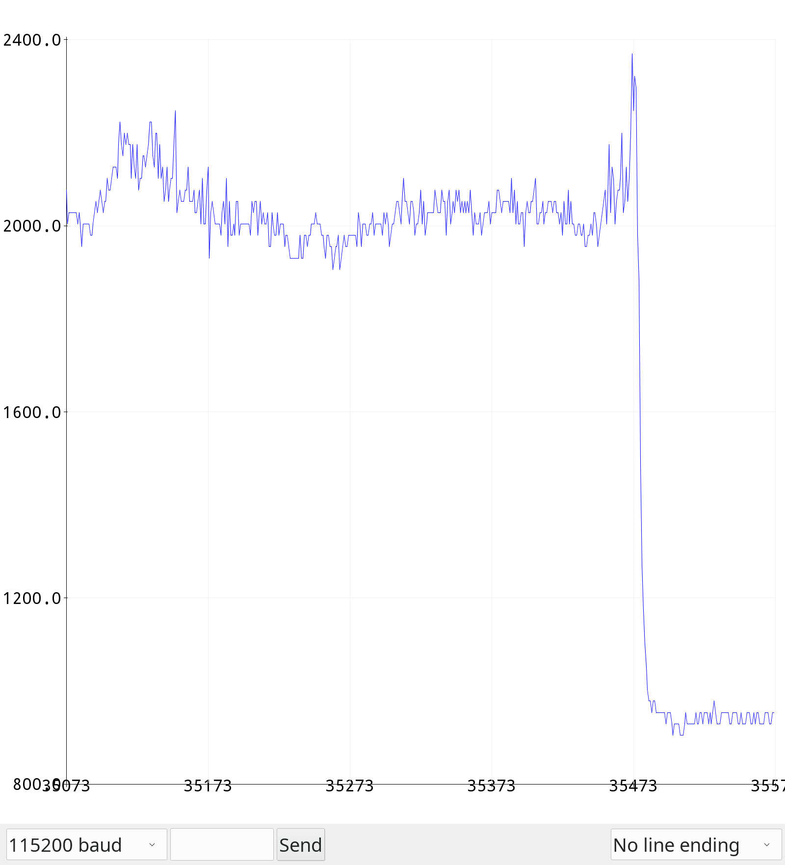
I’ll try out some new workholding tomorrow though. The thing that makes me hopeful is that the 1.5mm cut had a decent chunk of time where everything was calm and the 1.5mm cut was only taking ~2.1A. If the issues were due to an inherent flaw in the frame, they should have been persistent throughout the entire cut, but they weren’t.
So I’ll try throwing a bunch of clamps at it, which should make it much harder to lift out.
The other thing that makes me hopeful is that at 1.5mm, if I’m still only using 2.1A, that’s only 50W, so I’ve still got quite a bit of headroom, especially given that 1.2mm was 2A. If things are linear, 0.1A bought me 0.3mm depth and I’ve still got 0.9A left, which could mean an extra 2.7mm, for a total depth of 4.2mm.
At 4.2mm, it’d actually be doing what Millalyzer claims takes 48W, which would be a big efficiency improvement on the numbers I’ve seen so far.
Of course, I have serious doubts that the machine will be able to do that. I suspect it won’t be rigid enough, but I can dream.
Anyhow, I think I’ll try following in Vince’s footsteps and add ballscrews to all axes and linear rails to the Z-axis. That ultimately shouldn’t be too big a project:
Adapter plates for the ballscrew nuts
4 precision milled but small plates for the Z-axis:
One plate flush against the X-axis carriage with the linear rails attached
Two plates that screw into the top and bottom of the X-axis carriage as well as the top and bottom of the plate with rails
One plate to hold the actual spindle, attached to the linear rail carriages
Something to attach the Z-axis to the ballscrew nut
@Vince.Fab can you share any details about your ballscrew nut adapters You said they were “close”. Do you think it’ll be any real trouble for me to machine? Did you make them from Aluminium or steel?
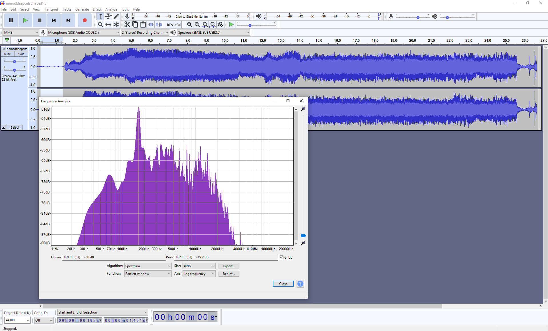
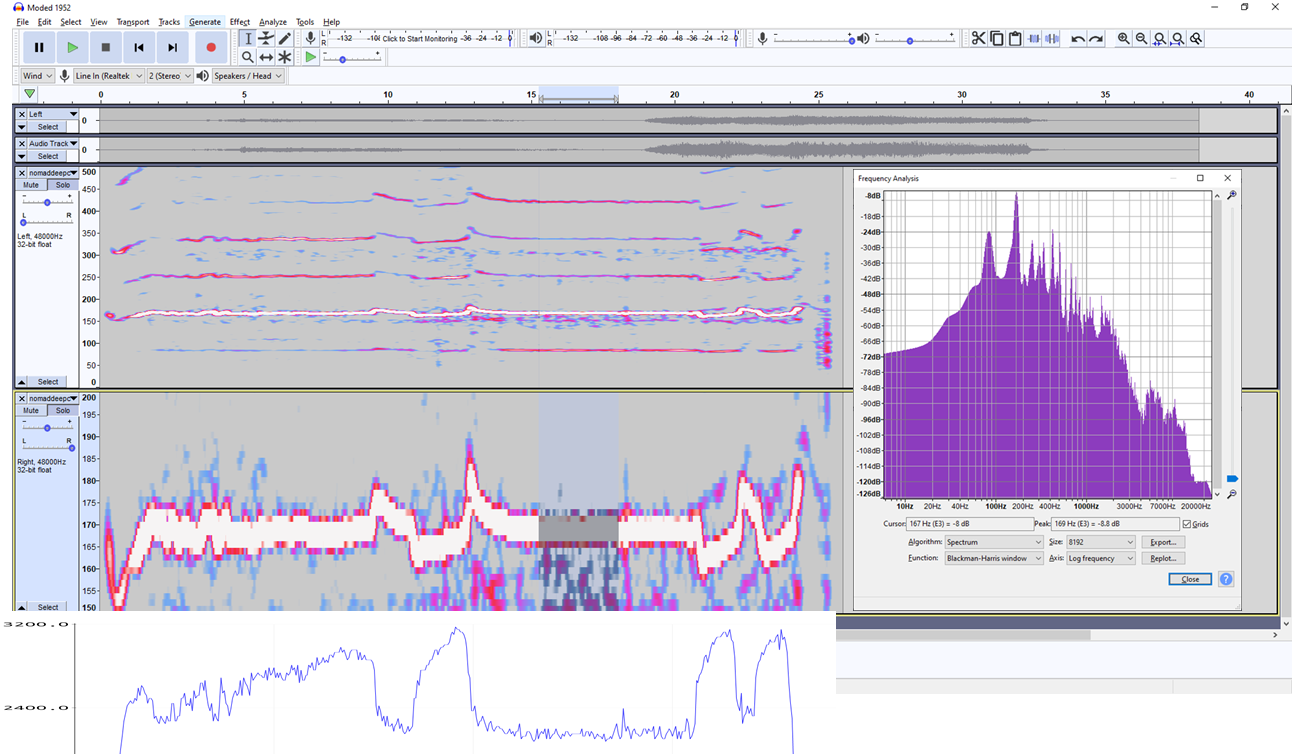
I grabbed the audio of your 1.5mm cut file in Audaticy (as @gmack did above), it’s really worth a download (it’s free).
In the lead-in before the cut we can see the main frequency peak around 169Hz, is this running at 10kRPM?
Note there is little noise around this peak, there’s some rattle and hum from the machine above the base frequency of the spindle (and there’s presumably some gearing between the motor and spindle, any idea what ratio?) but there’s very little below the cutter frequency;
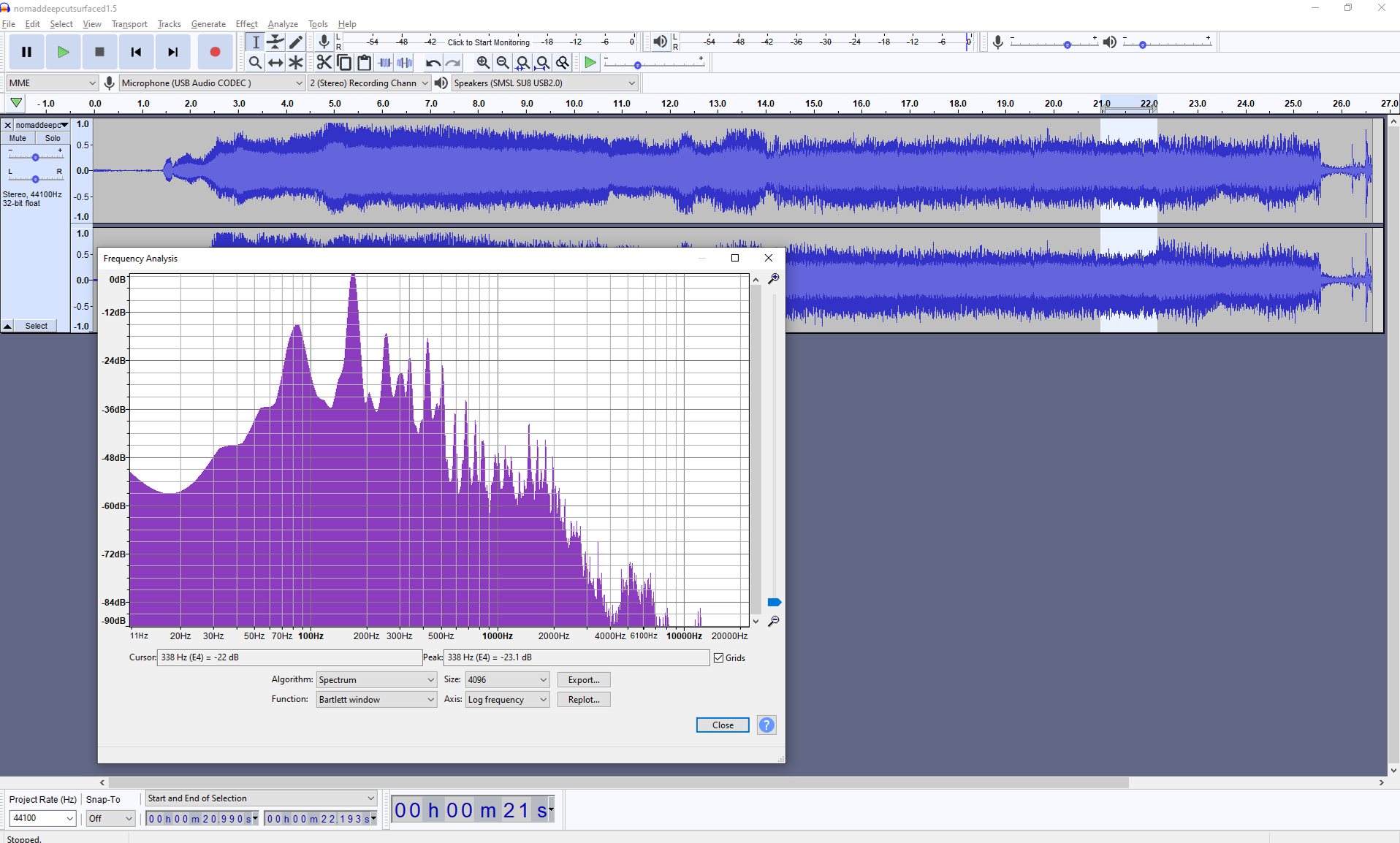
Here’s one in the first part of the cut, note that we’ve gone up 50dB and brought the low frequency noise up by >> 40dB. That’s significant because it’s below the cutter frequency and indicates that we’re exciting other vibration modes.
We’ve also picked up a whole load of high frequency noise from assorted vibrations.
We have the first harmonic of the (single flute cutter at 10kRPM?) at ~340Hz now, the further harmonics are mostly lost in noise.
And later in the cut, this picks out the 338Hz first harmonic of the cutter, but we’re also seeing a substantial peak at ~83Hz which is the first subharmonic (is the belt drive a 2:1 gearing?)
Some of this will be down to the other linear motion parts of the machine but it would be interesting to compare these spectra with a “clean” cut where the machine isn’t trying to shake itself to bits.
It’s going to be a step at a time, it would be really interesting to get a series of base measurements for deflections and backlash on the machine along with some spectra and power data for repeatable cuts to test progress…
That I can do. I’ll do the same everything but just drop the axial engagement down to 0.2mm.
I can do the spectra easily enough. Regular backlash, I’ve already measured and compensated for in my controller. I haven’t tested stiffness of the AB nuts though. Power I can also do.
Maybe for power, I should record progressively deeper cuts and see if I can plot them on a graph and produce a curve. It’d be really interesting, even if only to see if it’s linear or not. It’d also be interesting to see how the curve changes when ballscrews etc. have been added.
Oh and for spectra, I should put a microphone in the enclosure and/or a few accelerometers scattered around the machine… Maybe I’m getting into overkill territory though (or “so much work that I’ll never actually get around to it” territory).
It looks to me like the sensor-less motor controller is doing a pretty good job maintaining speed, as it should. Apparently the motor isn’t the problem. Sure wish we could see the motor currents!