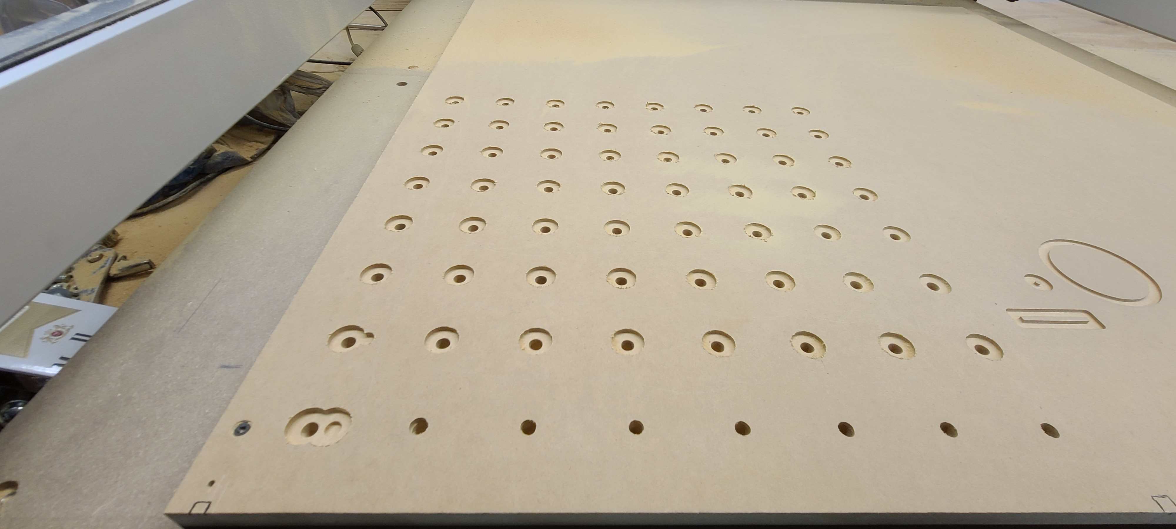
Hello, hoping to find some help with a problem I have. So I was in the process of making a new spoil board for my XXL, I made the design on Vcarve desktop, ran it on a test piece and everything looked good. Today I tried it on the actual mdf board and everything was going great, until about the 95% mark and the machine disconnected from carbide motion. So I though, no biggy, I’ll just send it back to my work zero and just let it run through until it catches up to the remaining 5% left of the job. Well for some reason, even after i reconfirmed the work zero 3 times, the tool toolpath is now starting almost half an inch to the right of where it was supposed to be. I can’t figure out why its doing this and I would really like any advice that can help me figure this out and maybe salvage this spoil board. The new spoil board is affixed to the stock spoil board by screws in all four corners so I know it didn’t jump on me by accident. Thank you!
Long Shot: If your zero point is accurate, maybe it’s the home point that is off. After the disconnect, did you power off the Shapeoko, power it back on and let it re-do it’s homing cycle?
Yeah, in order to get the xxl to talk to the pc again after a disconnect, i had to shut of the machine and turn it back on to get it to reconnect. I hit the initialize on Carbide Motion and it returned it home to the upper right hand corner. If that’s what the homing is. I reset my zero, and then started the toolpath again, and thats when it started doing everything off to the right of what it originally did. I’m pretty bummed out that I cant even get a simple waste board to form lol
Where is your work zero set and what method are you using to set it ?
When you said you reconfirmed the work zero 3 times, can you describe what you checked ?
Extremely long shot: if you set your zeroes using the probe, on the lower-left corner, there may not have been enough clearance on the left for the probing moves, and the gantry may have hit the left rail, lost steps, and then the zeroing process would have been off. But then again, you would have heard (and mentioned) the ugly crashing sound, and assuming you used the same zeroing method the first time, you would have had the same issue then, so that’s probably not it.
After you set zeroes, can you verify that you can actually the coords read 0/0/0 in CM ?
Using Carbide Motion to set X Y Z zero points and reconfirming by checking the plot numbers, thats how I’ve been confirming it digitally. And for mechanical zero i drew a 1/4 in by 1/4 in box around the bit on the work piece to reposition it. Even if i was a few thousands off the zero mark, it still wouldnt explain how im re carving the same tool path almost 1/2 an inch off of the original tool path. And yeah i didnt hear any clashing or crashing during any of the travel periods.
The investigation continues then. Can you post the G-code file, and measure the X and Y distance between the center of your 1/4"x1/4" zeroing box, and the center of the lower left hole for the second run?
Ill post that info after my lunch break here in a few.
This topic was automatically closed 30 days after the last reply. New replies are no longer allowed.