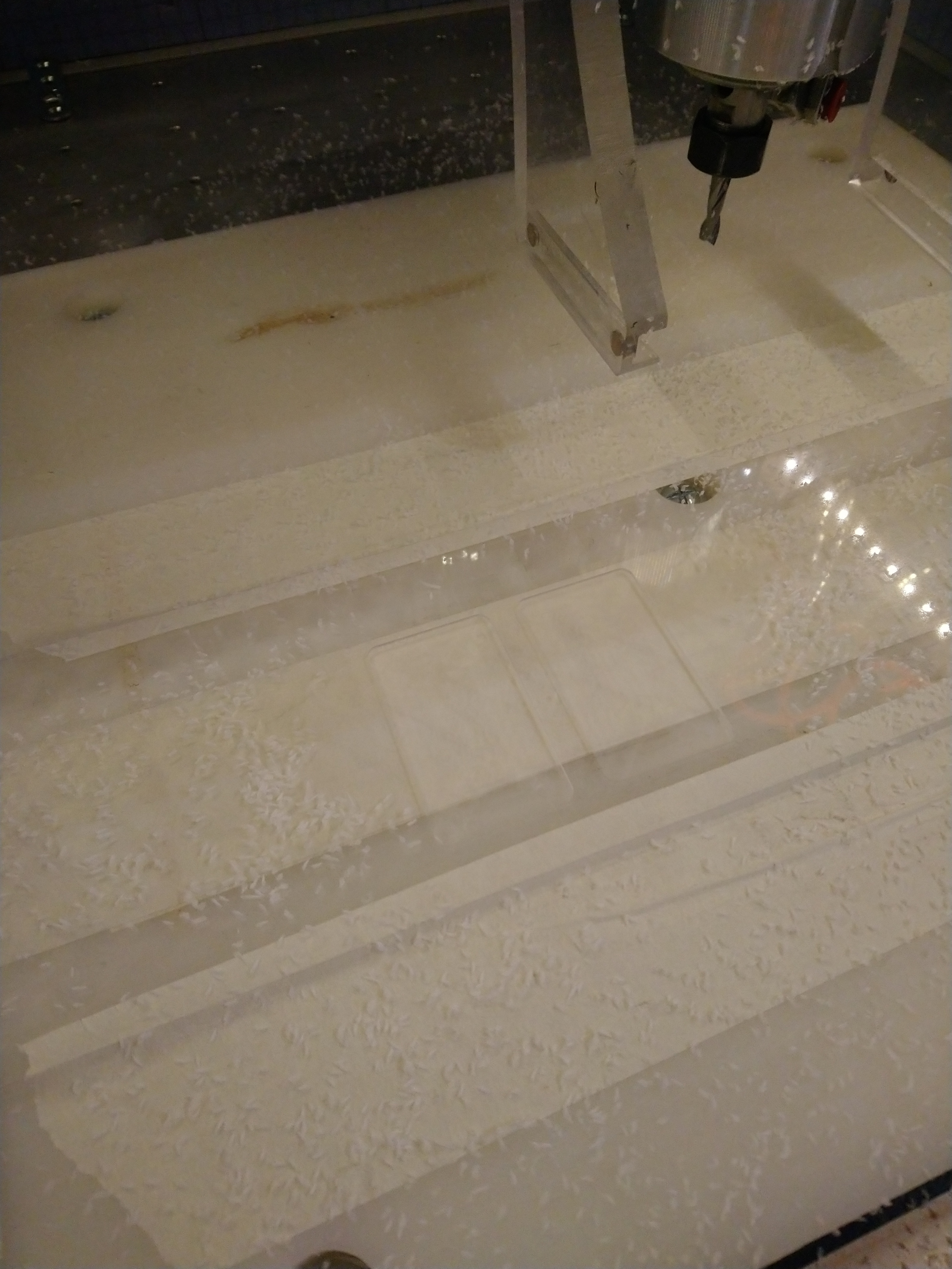
By the by, I forgot to post it earlier but I retried cutting the pocket in acrylic that was perfectly clean at 25.000RPM/100ipm (on the left), at 10.000RPM/40ipm (e.g. same chipload, on the right), still 0.04" DOC, and the result is identical (perfect edges, clean chips, no melting):
This got me thinking, after I did more tests in HDPE today with a 2-flute 1/8" endmill, and saw this:
- 0.002" chipload at 25.000RPM / 100ipm worked fine (as previously discussed)
- 0.002" chipload at 10.000RPM / 40ipm was bad, borderline melting, with stringy chips.
- when I used feedrate override to 200%, I got clean chips again. Which means I had to push chipload to 0.004".
These two settings giving correct cuts have a x2 difference in chipload value, but have nearly identical MRRs. In the end, isn’t MRR what matters to remove heat (cf. your statement above) ? And then it would not really matter whether the material removed is by lots of tiny (0.002") bites per minute, or half as many larger (0.004") bites.
Of course there would still be the matter of higher forces for lower RPM, but in soft materials like HDPE it probably makes very little difference.
Does that make sense ?
1 Like
It seems likely that the increase in feed rate from 40 IPM to 80 IPM is what stopped the melting. I’ve used up 200 IPM in wood on the Shapeoko (even less likely to burn/melt).
Single flutes really shine in heat sensitive materials due to the much larger chipload you can take without increasing the overall load.
I ran 3lbs of descaled hot rolled steel through the Nomad last night for drag truck wheelie bar brackets.
5krpm 0.125 4 flute
Adaptive around 0.001ipt, 0.005 axial/0.010 radial
Bore at 0.005 ipr
Full width contour slotting 0.250 deep in 0.005 steps, 0.00075ipt
Wd40/synthetic/alcohol mix running wet and also gives clues on heat build up/input
All based on minimums and increased loads based on machine performance realtime.
4 Likes
@Julien and Others?
I tried to make the workbook more user friendly and useful for logging results. 2019-07-13 Speeds and Feeds Workbook.zip (142.1 KB)
Your new HF Spindle’s VFD should allow you to monitor the current into the spindle. Since the speed of the spindle is determined by the frequency of the VFD’s outputs, your speed setting should be pretty accurate. Since spindle power is proportional to speed and torque, and torque is proportional to motor current, spindle power can then be calculated by monitoring motor current. Entering spindle current input when not cutting and when cutting onto the worksheet thereby enables it to calculate the net cutting power and actual K Factor for the material as shown here:

Saving those worksheets could provide more accurate K Factors (for everyone?) as well as a basis for recollection and comparison with subsequent operations (to determine if something has degraded/improved).
5 Likes
Fully agree that single flutes help, and I had convinced my self earlier about this by testing it, and thought it was because:
- it allows to reach a higher chipload for a given RPM+feedrate combo
- it’s optimal for chip evacuation, therefore less chances of recutting, therefore less heat?
However earlier in this thread there was no agreement whether thicker chips took away more heat, compared to a larger number of smaller ones (max RPM+ FR set to get 0.001" CL, @gmack’s approach)
This random scientific paper about cutting super hard metal, highlights that higher chiploads mean more heat:
So I’m back to believing that short of removing very thing chips very quickly, removing larger chips slower is a good “workaround”, that compensates for the increased heat ?
So one more confirmation that the [0.0005" to 0.001"] minimums are relevant, and that wide and shallow also works (your contour/slotting cut)
4 Likes
Thank you, I will have a look of this new version.
I need to do a few more tests and last minute projects with my router before setting up my spindle, but if indeed I have a way to measure K factors based on the input current read on the VFD, I will happily contribute to the measurement of K factors dabase for various usecases.
And I like the idea to save a copy of the worksheet each time one does a specific cut, and archive that in a separate tab for reference. Actually, we discussed a while back what would be a good format for sharing feeds & speeds on the forum, providing ALL relevant information, and I think posting those screenshots of the worksheet as you do would be an excellent way to standardize the info.
3 Likes
I found it useful to record, save, and link to videos of the processes too (memory is cheap!) You can then replay the video to get as many current reading samples as you wish. It will also help you understand what happened when something goes awry (like the spindle and/or feed rate changes, something slips or breaks, the workpiece comes loose ,etc.)
Your VFD probably also has a digital data output interface that would enable computer logging and real-time display of motor current and other operating values. That software (Carbide Motion?) could also provide real time feedback of cutting forces, powers, etc. to help the operator (and/or software) optimize the cutting parameters.
2 Likes
Until I embark on a K-factor & temperature measurement adventure (now delayed because I need a new dust shoe, and that requires my 3D printer to behave…), I figured I would take some time to look into another topic, which is required chiploads/feeds and speeds for V-bits and Ballnose endmills.
Try as I might, after hours of reading from tons of different sources, I could not find any useful background/theoretical info for selecting F&S specifically for V-bits. Common answers I have seen are:
- that since depth of cut and therefore effective cutting diameter varies constantly during V-Carving, it is pointless to aim for a given chipload (I don’t get that one, since chipload is independent of endmill diameter…)
- that feedrates need to be conservative because that pointy end is weak (which makes no sense to me either)
- that RPM need to be as high as possible, because at the tip the SFM is really small, close to zero actually. This one I buy.
- but mostly that one should “try and see what works”. Very down to earth, but not what I am looking for.
BW has a page about how V-bits are different and F&S need to be compensated accordingly, but of course zero details on the nature of these adjustements in GWizard…
So, do you guys have recipes you use to select feeds & speeds for V carving?
Similarly for ballnose endmills, I have not found anything interesting. I presume mostly because in 99% of cases ballnose are used for finishing 3D jobs and the stock to leave is so small that pretty much any feeds and speed could work?
Opinions ?
4 Likes
I usually compensate with varying router speed as the cut deepens.
In my experience V bits are extremely durable but I also use good bands, Kyocera and Destiny. The flat on the end on mine are around 0.010 and they have cut pretty much everything without chipping out or any issues. On feedrate, really depends on the material but the end of the cuts with v carving will usually be around full engagement and it can have a tendency to chatter if you don’t keep an eye (metals). Lubrication is important in metals, especially the first few passes, helps with the tip sfm issues. Keep in mind you can also use v bits for adaptive cutting, I like a 0.009 opt for two flutes (has to be less that tip flat diameter)
Ballnose -
https://www.iscar.com/ita/Calculators.aspx?units=M#
Lots of good calcs there, thinning based on type of cut and surface quality. Imo ballnose cut quality is mostly on how you leave your finishing stock. Its still a good idea to cam out based on chipload but keep in mind you can push much harder because you aren’t removing that much.
One tip is for finishing it to run square approaches as it can have a certain visual effect. Stepover equal to chipload, minimum 0.001/0.001 and I usually max around 0.005/0.005 depending on desired surface or time limit.
Also when using fusion it can be a good habit of duplicating your adaptive roughing and running it with a ball and rest machining to the previous op. This will get 3d surfaces much closer to final shape and minimize load spikes of going directly from square rough to ball finish.
edit deleted stuff about sfm. Doesn’t really matter here.
2 Likes
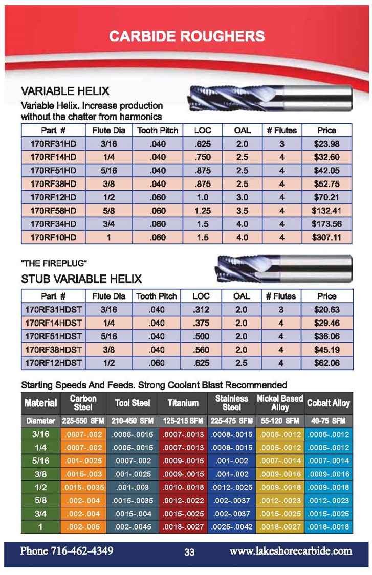
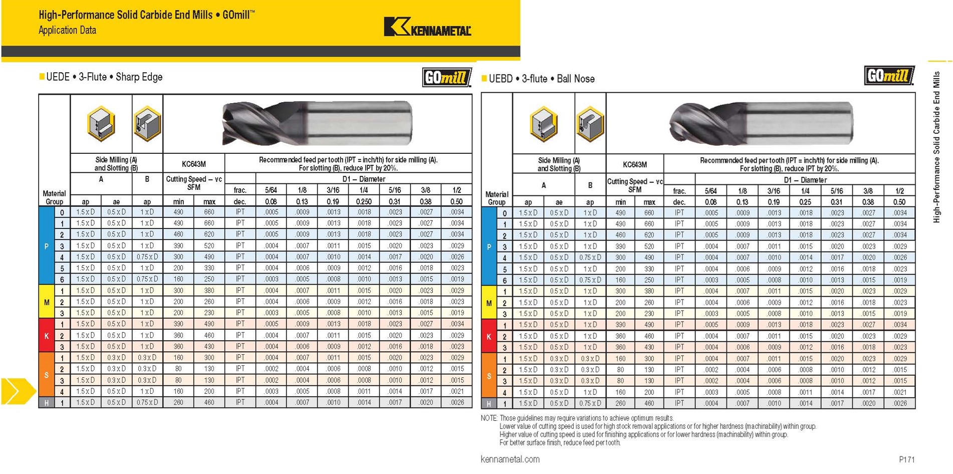
IMO it’s probably wise to go with the endmill manufacturer’s recommendations (unless they used GWizard to develop them ![]() ). As shown below, it probably makes sense to use the same speeds and feeds for both ball and flat nose endmills. KISS
). As shown below, it probably makes sense to use the same speeds and feeds for both ball and flat nose endmills. KISS
Note that the chip loads are proportional (K) to endmill diameter (as you previously pointed out) for a given SFM. That keeps cutting edge impact forces the same for all diameters because they’re inversely proportional (1/K) to RPM, which itself is inversely proportional (/K) to diameter. Hope that’s confusing enough! ![]()
That, in conjunction with the “for better surface finish, reduce feed per tooth” note, suggests that the endmill manufacturer chipload recommendations are maximum rather than minimum values.
It would be interesting to see how those SFM recommendations correlate with material harnesses and K factors. (Kennametal has calculators too).
3 Likes
Their user guide has a different definition of HSM than most(?) - “High Speed Machining defined by very shallow radial width of cut and increased table feed, due to radial chip thinning effect.”
1 Like
BW mentioned this diversity of HSM definition/origins in this article. Re-reading that, and especially the part about “various shops discovered HSM techniques can work well even on slower spindles”, makes me think the core of HSM is more generally to take lighter (low engagement) but faster (as in feedrate) passes.
Or maybe the word HSM just got so trendy that everyone started using it just to be part of the gang 
Definitely agree. Both because of what you say, and because I guess it would be dangerous for them to advertise a single value that is a minimal chipload, and could be erroneously compared to the max value from another manufacturer. Which is why I was (pleasantly) surprised when Vince pointed out that Lakeshore provided minimums too.
Ok so overall,
-
F&S for ballnose can be the same or even more aggressive than for square endmills since:
- at least Kennametal recommands identical chiploads for this ballnose endmill example vs its square sibling.
- ballnose usually comes after an initial roughing pass, so has less material to remove.
- ballnose can take at least the forces that a square endmill can and probably much more, since it does not have the sharp corner angle, so is less susceptible to chipping.
-
for V-bits…still unclear to me. @Vince.Fab, I hear the general (and very useful) tips you provided, but it does not give me a recipe for predetermining a proper starting point for F&S for a given situation. What I think I’ll do is check what CC, VCarve, or various guides out there recommend for a few typical situations (say, 60° and 90° V, in hard wood and in soft wood), and see if a pattern emerges.
I want to use a profile (router) bit for a project and I’m scratching my head on the best F&S to use as the set I have (like most I suspect) came with no specs. As many have experienced burning wood when using them manually, it can be tricky to find the sweet spot between a good cut and burning and chips and most of us will rely on the sound to make adjustments. From what I have seen, recommendations are for maximum or range of RPM for a given bit but no F&S like in this article from Rockler. In the case of a CNC, it could lead to a quick crash if FR is too ambitious for the bit used.
I found a set of F&S specs for bits from Freud but it does not mention profile bits.
I’m sure many have used them in their CNC but I have not seen information posted. Does anyone have recommendations based on experience for common bit types e.g.: roundover or cove bits?
In the process of trying to find one, I came across a document from Shopbot that provided target chipload for V bits and ball endmills that may be of interest to @julien but not for profile bits
2 Likes
Well, after a bit of more digging, I found that some but not all profile bits in the CNC section of Freud Tools have a good calculator on the page for the individual bits that provided the Feed rate range at a given RPM. It looks like many of the 1/4 shank bits do not have that calculator function unfortunately.
for cove bit, maybe this set of F&S could be of interest ? (I have no experience with cove router bits, but this amana “core box” looks similar)
EDIT: so it looks to me like you could just apply the “usual” chipload guidelines (maybe the low end of the range), and compute F&S as you would for and endmill
1 Like
- ballnose can take at least the forces that a square endmill can and probably much more, since it does not have the sharp corner angle, so is less susceptible to chipping.
Yep, especially due to the lack of a corner tip on a common square end mill.
That is the area most prone to damage that can escalate as soon is it wears/chips.
This is the reasoning behind bullnose endmills or corner radius endmills. Their ability to be pushed as a rougher (lack of weak tip), yet have a decent stepover (b/c mostly flat) so you have good MRR. You can push a ball end mill as well, but you have to deal with the cusp of stepover on the floor surface.
3 Likes