Origin/consistency of chipload recommendations

The more I think about it, the more I like this approach. I was already bought on the fact that max achievable DOC is the major difference between the Shapeoko and more rigid machines, but I am still following an “in-between” approach of reducing both the DOC and the recommanded chiploads.

My revised best guess for “starting point/ minimal chipload” is currently :

MDF Soft wood Hard wood Acrylic Aluminium
soft wood + 25% <= hardwood + 25% <= Acrylic + 25% <= Aluminium + 25% <= baseline
1/16" 0.0006 0.0005 0.0004 0.0003 0.00025 half of 1/8"
1/8" 0.0012 0.001 0.0008 0.0007 0.0005 half of 1/4"
1/4" 0.0025 0.002 0.0015 0.00125 0.001 baseline

I would be quite interested to see how Steve’s chipload relates to this reference, or what everyone else has to say on these values.

2 Likes

Running a minimal load doesn’t guarantee the best cut performance or finish, but it should prevent many of the issues people have.

1 Like

Well… The only specific I have is that the aluminum is 1/8" thick ( I still have a scrap in the garage.) Unfortunately, this project was a friend of mine’s and he did ALL the CAD and design… all I did was take his gcode and load it into the machine. I do have some pictures attached to show what we were making, and some short clips that I uploaded to youtube so you might be able to estimate better than I can…

The only thing I THINK I remember properly is that we were cutting 0.5mm at a time. This memory correlates because I remember it taking 7 passes to cut all the way through…


Is the recommended chipload documented by the manufacturer for a specific bit? (maybe per material type?) It seems logical that they’d have a design spec for this?

Yes but not everyone publishes the information. Amana for example has a guide for different bits (family) but Carbide does not have a recommended chipload for the bits.

1 Like

…and there is an ongoing debate whether or not manufacturer recommandation are suitable for the Shapeoko, which is far less rigid than the pro CNC machines the manufacturers design their tools for.
The values I mentioned above are my try at finding a suitable compromise between averaged recommandations from endmill manufacturers, and the chiploads that correspond to Carbide’s recommanded feeds and speeds charts (that a bit random, at times)

4 Likes

IMO, at least with wood, its more about the Shapeoko’s force and power limitations than cutter chip-loads (which were seemingly developed for much more capable machines and/or advertising purposes.) For yellow poplar and hard maple chip-loads of 0.0004 - 0.005 in/tooth have worked well for me with both 1/8” and 1/4” 2 flute carbide endmills. Since reducing chip-loads reduces both force and power requirements (and/or enables greater cutting depths to extend tool life), minimizing it seems like the best approach. For wood, 0.001” is probably a good goal for good quality sharp endmills.

Speeds and feeds calculators like GWizard are useful for calculations. But, unfortunately, the accuracy of their performance predictions is often severely limited by the accuracy of their estimation of the net unit power required for the cutter and workpiece. Net unit power is the amount of cutting power (HP or Watts) required to achieve a given material removal rate (MMR) in the workpiece with the cutter. Cutting power for the Shapeoko “1.25 HP” routers is likely limited to 400 – 500 Watts. MMR (in3/min) is depth of cut [DOC] (in) times width of cut [WOC] (in) times feed rate (in/min). Shapeoko3 feed rates are limited to 200 in/min. Cutting power is proportional to cutter speed (RPM) and cutter torque (in-lbf). Cutting force (lbf) is cutter torque (in-lbf) divided by cutter radius (in). Shapeoko3 X-axis cutting forces are limited to 20 lbf. So, Shapeoko performance is limited by it’s 20 lbf force limit and it’s 400 – 500 Watt router power limit.

My measurements suggest that the latest version of GWizard (v4.72) can be useful to help evaluate/optimize performance for some materials by forcing/locking its speed and feed and then adjusting parameters and augmenting its calculations as shown below. (Too bad it doesn’t display and/or allow setting/locking force! -BW?).


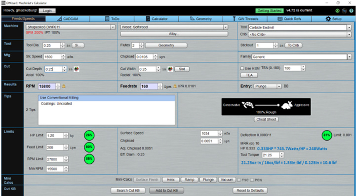
GWizard accurately predicted 10.6 lbf cutting force, 0.333 HP (248 Watts) power, 0.0051 Inch per Tooth (IPT) chip-load, and a 10 in3/min Material Removal Rate (MRR) for one of my test cuts in poplar. The net unit power for yellow poplar (540 Janka Hardness) is apparently approximately 248Watts / 10 in3/min = 25Watts / in3/min. Although that version of GWizard uses this only for softwood, my measurements suggest that it’s also more appropriate for MDF than the 40 Watts / in3/min it uses for MDF, plywood, and soft plastics. GWizard uses 74.5 Watts / in3/min for hardwood, hard plastic, and wax. Based on my router cutting power analyses, 74.5 Watts / in3/min seems about right for Baltic birch (birch is 1470 Janka hardness), but too high for Santos mahogany (2200 Janka hardness) and sugar maple (1450 Janka hardness). It uses 159 Watts / in3/min for all types and alloys of aluminum. GWizard doesn’t indicate which type/alloy it uses (BW?) but that’s consistent with what several other calculators commonly use for 6061 T6.

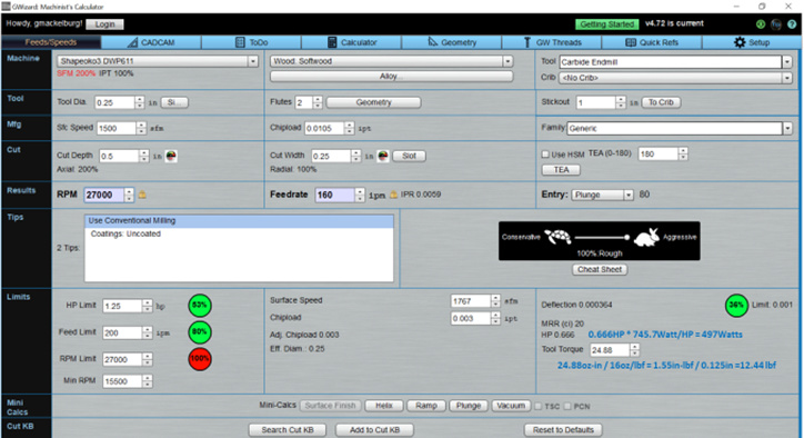
With a router speed increase from 15,800 to 27,000 RPM and DOC/MMR doubled, GWizard predicts 12.44 lbf cutting force, 0.666 HP (497 Watts) power, 0.003 Inch per Tooth (IPT) chip-load, and a 20 in3/min Material Removal Rate (MRR). That’s likely near the maximum power available from the Dewalt router. Note that increasing the speed allowed the DOC (and MMR) to be doubled with only a 17% increase in force.

To cut Baltic birch, which has 3 times the net unit power, the MMR would need to be reduced by reducing the DOC, chip-load, or some combination thereof by a factor of 3.

6 Likes

Will Adams posted an open-source feeds and speeds software that allows you to fix the radial and/or axial cutting forces, which seemed like a much better way to determine ideal cutting parameters than with some arbitrary conservative/aggressive slides that GWizard has. Albeit, this is only for adaptive milling parameters but that’s my primary cutting strategy nowadays anyway.

http://brturn.github.io/feeds-and-speeds/beta.html

3 Likes

Awesome - thanks for the link.:slightly_smiling_face: The unit power for wood is twice what I’ve experienced for the hardest to cut wood, but it can be customized - so it really doesn’t matter. That calculator appears to be useful for more than just adaptive milling though. It can automatically adjust parameters (like feed rate) to reflect other constraints (like forces and chip-loads).

Also, I was only recommending using GWizard as a calculator to aid users in evaluating the likely effect of changing parameters. Your linked calculator makes that a lot easier.

2 Likes

That’s true, I forgot it has slotting, drilling, profiling, and adaptive milling strategies.

I have yet to figure out what parameters need to be changed to predict Shapeoko milling. Essentially, I don’t know what forces are acceptable to use as constraints. 5 lbs? 10 lbs? 15 lbs? Cutting forces are not something I can easily obtain nor know what might cause chatter.

2 Likes

Cutting forces can be estimated by measuring router/spindle input power increases when cutting. Force constraints are dictated by accuracy requirements (which is a function of machine torsional stiffness).

1 Like

Since this thread is to basically create a Shapeoko cookbook, I think that saying it can be calculated does not provide something useful in this case. This is so someone does not need to use a calculator with a million variables that are daunting for many users. As Jonathan said, should the unmodified Shapeoko 3 use 10lb or 15lb in the calculations? Would this be the same for an XL or XXL? How much could you increase if you had an HDZ modified?

3 Likes

I think we agreed that the only thing we will realistically be able to determine is a set of reasonable starting points that are not out of the blue, and for me that’s already a big deal. I’m absorbing each small piece of wisdom that is left here, and will try to make a synthesis (if only for myself). Keep the comments/tricks coming !

7 Likes

I haven’t heard anyone talk about tool sharpness. I’ve found hss tool to usually be sharper than lower cost carbide but that’s all by feel. This is one reason I never go under 0.001 for inserts.

Cookbook-
“Minimum chip thickness is 5-20% of the cutting edge radius. Below that level, chips will not form and the cutter will “plow” across the workpiece causing plastic deformation and considerable heat.”

2 Likes

You use cutters with inserts instead of endmills? Can you provide a source for your quote?

https://www.buschmachinetool.com/milling-cutters

Two face mills for now but he was willing to make the APKT single insert in a 3/8.

2 Likes

So, your experience indicate that 0.001 IPT works well with inserts cutting aluminum (6061 T6?). BW says in the link that “Modern tools for aluminum are often much sharper, and can take less chip load. In general, indexable tools are less sharp than endmills, so they need higher chip loads.” What does your cutter manufacturer recommend for speeds, feeds, and maximum speed for the cutters that you use?

Dangerous game you play when potential runnout is more than desired chipload…take that how you will.

In my experience, hundreds and hundreds of hours cutting aluminum…0.001 maximal chip thickness has never ever ever ever lead me wrong with any tool I’ve used.

The only cutters ive used that were meant for 30,000 rpm were Datron endmills. 0.005max, I was averaging 0.0035 actual.

2 Likes

Yonico makes endmills that are rated for 35,000 RPM. PreciseBits’ are rated for 100,000 RPM. What collet(s) do you use with your Makita? Have you measured their runout?

1 Like

I regularly check TIR and usually adjust 0.125 and below. Using makita collets, Elaire, and cheap reducers. They are all usable and I try to have around 0.0005 tir although it’s not unusual to have up to 0.005-0.003 tir before adjustment.

Even on a 70watt spindle for t6-6061, 0.0008-0.001 minimums work very well.

1 Like