Origin/consistency of chipload recommendations

Gerald:

I have never milled plastic so far, did not burn wood either but the idea of doubling+ speed and doubling SFM while cutting a piece of maple scares me for some reason. The plastic issue was reported by others who were trying different F&S and found that the lower RPM gave better results. I’m not disputing the theoretical, I want someone braver to try it and report.

Do/did you ever use handheld or table mounted routers?

I was referencing the CNC. Yes many times I have used manual or table mount routers and yes I did burn wood/router bits and yes I operated at higher speed on a table router but I was controlling the work piece by hand and could easily pull it out if I sensed any issue (chatter, sound, vibration, etc). I also encountered times when the router went sideways and ruined my piece. Controlling speed by hand is not an exact science, I usually go by sound. In the CNC, it will continue on its merry way even if the gantry comes off or the bit wants to dig to the bottom of the earth or workpiece start flying until I can press pause/stop. I know others feel the same; doubting Thomas maybe but I still have all my fingers and eyes and I would like to see some experimentation on the Shapeoko before I rely blindly on the theoretical calculations and a recommendation to max out the RPM in most situation. The lower RPM still can lead to good results even if it may not completely optimizing the potential of the CNC.

Like many here I’m a hobbyist and if it takes me an extra 1/2 hour and feel safer and not have a splitting headache from the increased sound so be it.

2 Likes

Unless I missed something, this example demonstrates that 25k/100ipm is better than 9k/36ipm from a power perspective (only?), but the question remains whether this 0.002" chipload would allow to cut plastics without melting at 25k/100ipm. I’m game for putting that to the test tonight, in HDPE or Acrylic.

1 Like

@Julien
25,000 RPM consumes 2.77 times as much power and delivers 2.77 times as much MRR and is in contact with the workpiece 1/2.77 as long, so is probably 2.77 times less likely to melt it.

Here’s what those 25,000 RPM cuts looked and sounded like.
Acrylic 25k RPM 0.002 IPT at Full Speed.zip (2.4 MB)
Acrylic 25k RPM 0.002 IPT at 0.125 Speed (2).zip (2.3 MB)

Precaution: This video shows the workpiece between the router bit and fence, which is generally not safe. So please don’t try this at home!

2 Likes

@gmack:
Well, seeing is believing, I have to admit you opened my eyes.

  • First test: 1/4" 2 flute endmill; pocketing in HDPE, 25.000RPM, 100ipm, DOC 0.1"
    (excuse the lousy video quality, I captured this through the acrylic front window of my enclosure)

Perfect cut,

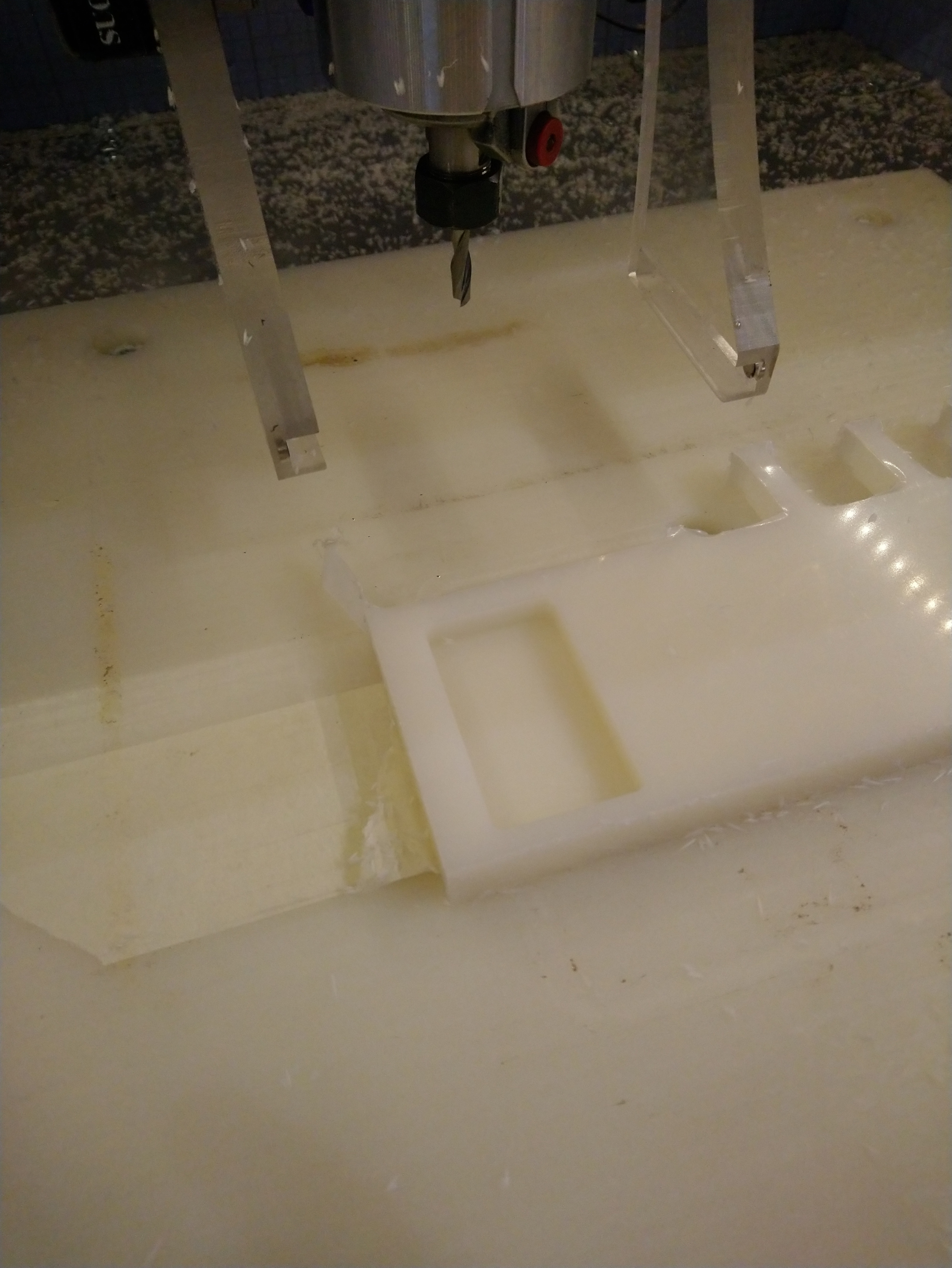
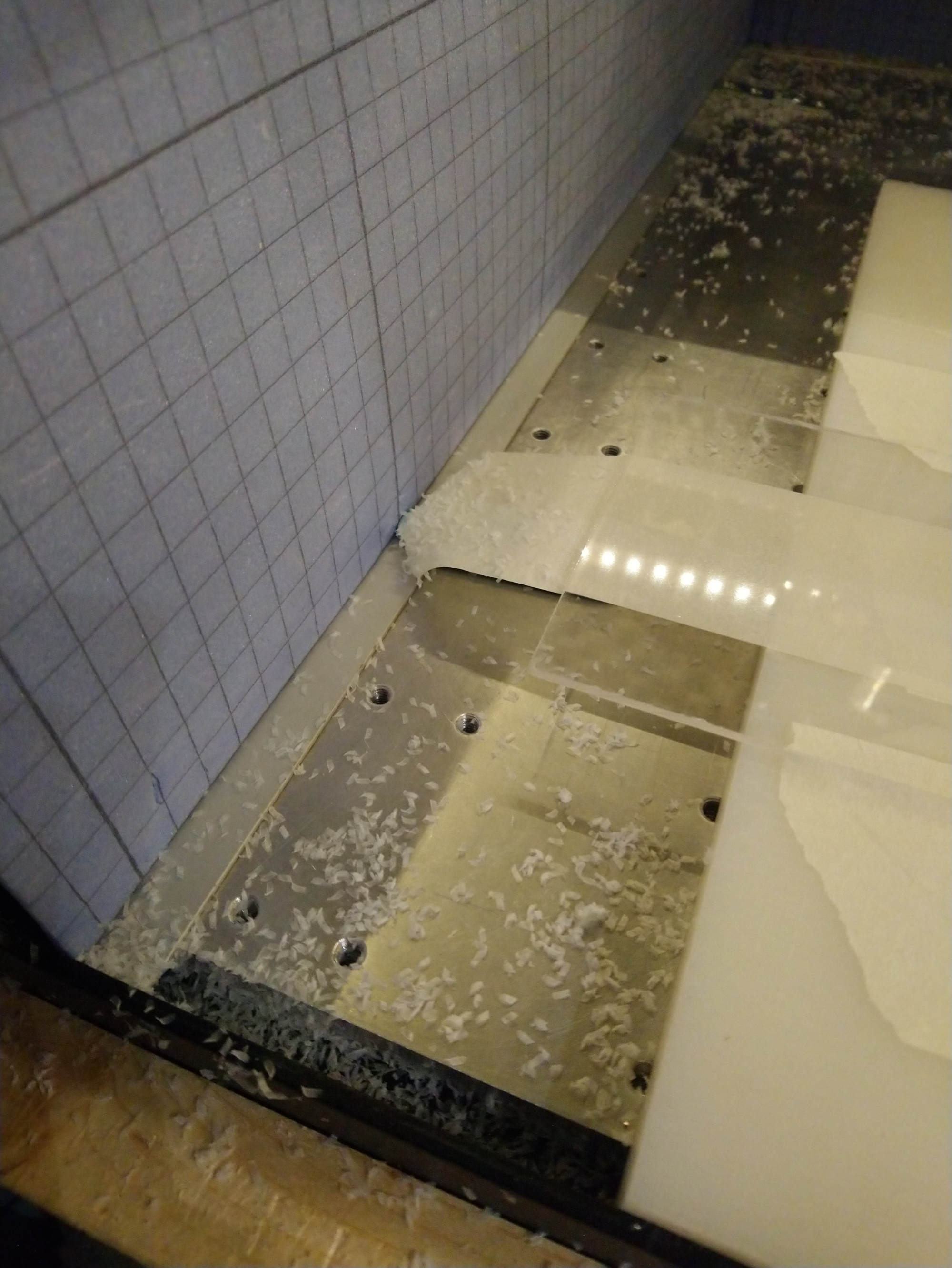
And nice clean chips

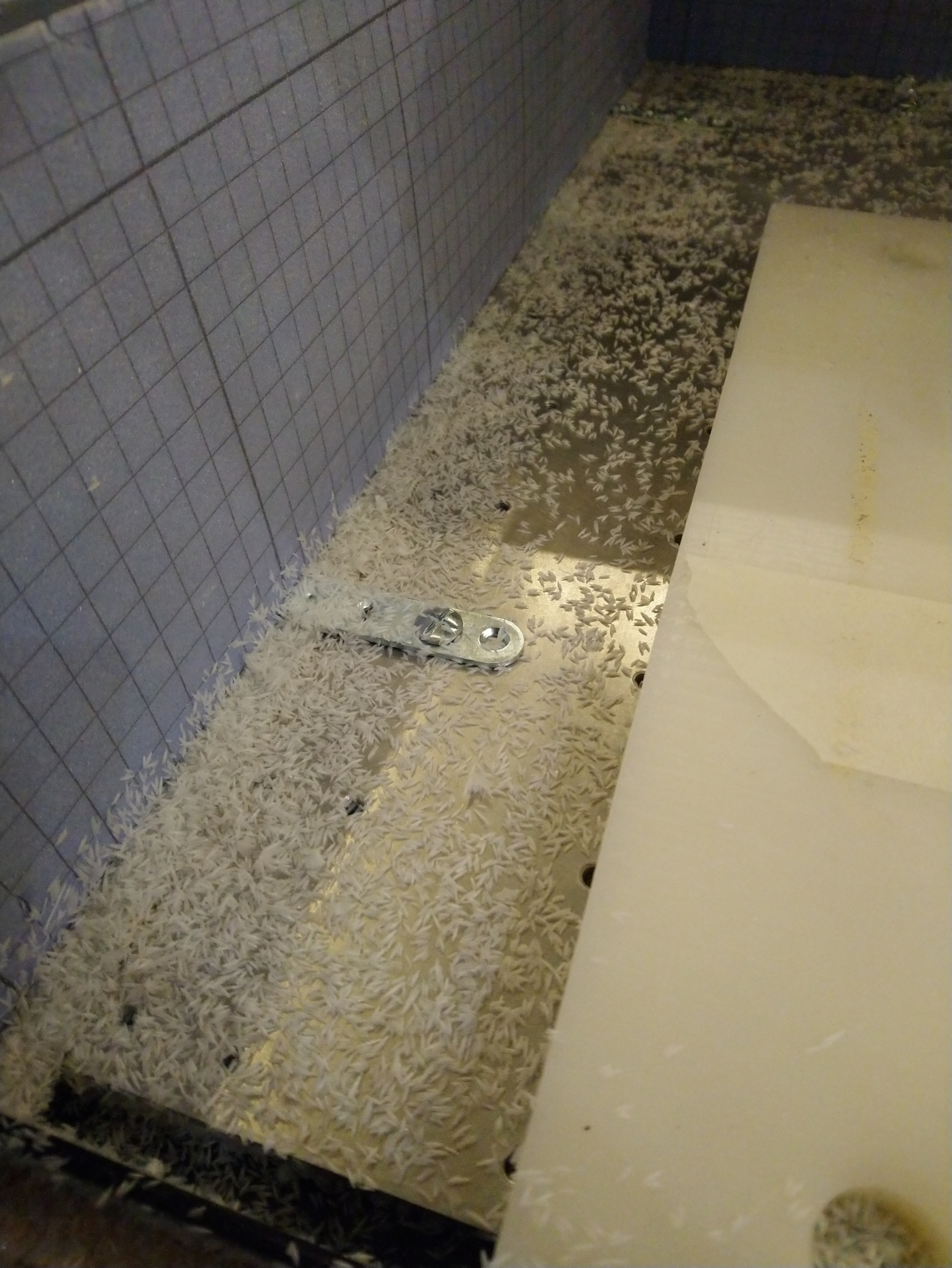
And the cutter was not even warm at the end.

  • Second test: 1/4" 2 flute endmill; pocketing in Acrylic, 25.000RPM, 100ipm, DOC 0.04" (just because my acrylic stock was only 0.08" thick):

Again very clean cut:


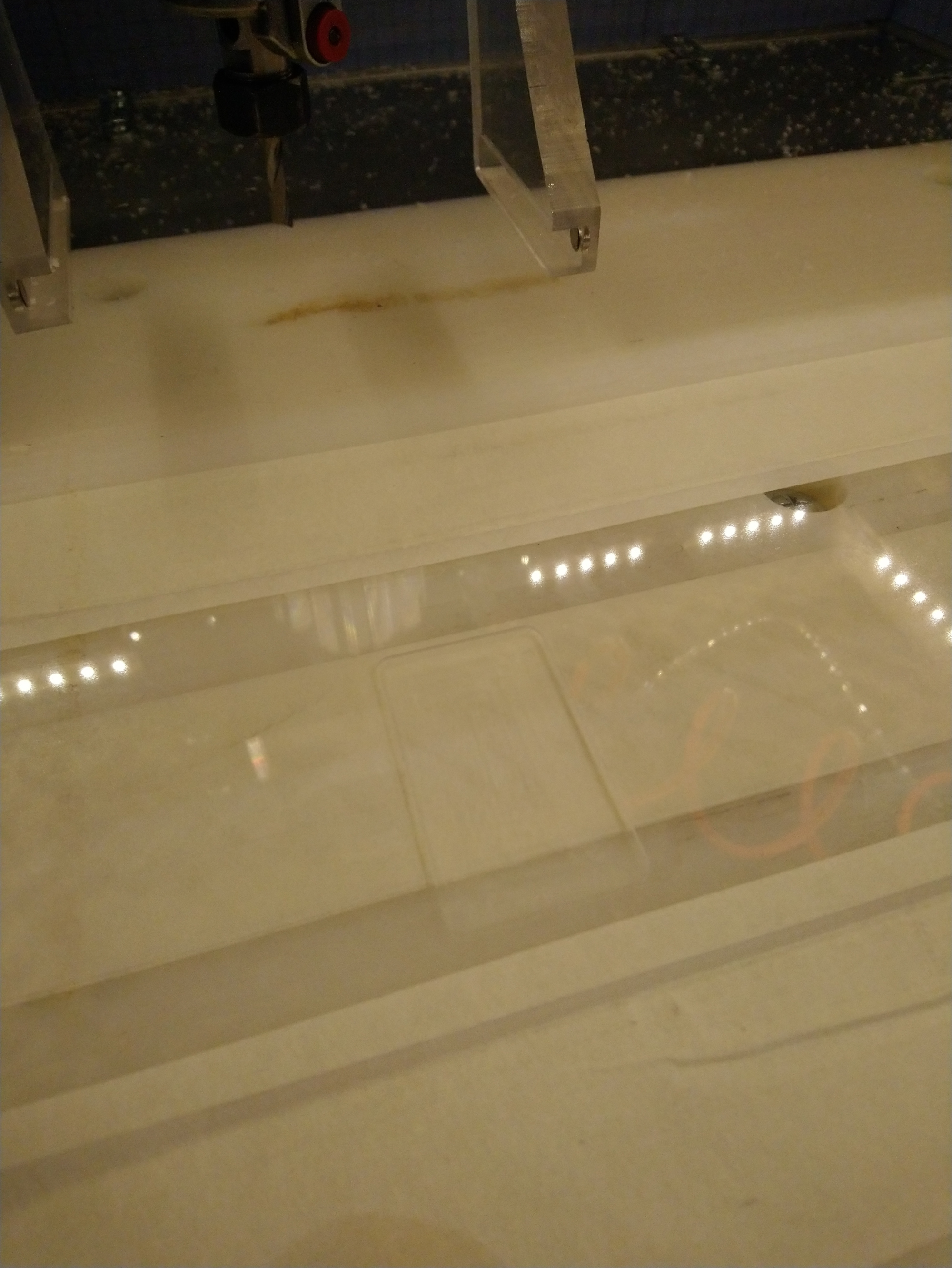
and still getting good chips:

And…I confirm that there is no way I can bear the sound 25.000 RPM for a long time, nor can my neighbors at 10pm.

So, it looks to me like there will be two conclusions:

  • if you can/are willing to max out RPM first, this is the best way (given the optimization of cutting forces) and you can use low chiploads
  • if you can’t or won’t, then you should increase the chipload (and accept higher cutting forces) as an alternative way to keep things cool. Call it the hobbyist/amateur way, it still works :slight_smile:

Now I can’t wait to receive my water-cooled spindle, to further venture in high RPM territory.

5 Likes

@Julien
" So, it looks to me like there will be two conclusions:

  • if you can/are willing to max out RPM first, this is the best way (given the optimization of cutting forces) and you can use low chiploads" Also minimizes heat generation and buildup
  • “if you can’t or won’t, then you should increase the chipload (and accept higher cutting forces) as an alternative way to keep things cool.” Generates more heat and heat buildup on the workpiece due to thicker chips and slower feeds rates which prolong any rubbing

“Now I can’t wait to receive my water-cooled spindle, to further venture in high RPM territory.”
Some others are already there with higher DOCs. The linked video demonstrates the value of quiet spindles @Vince.Fab is moving up to 60000,RPM

1 Like
2 Likes

I wonder if they use these German spindles.

@Vince.Fab Anything new with your Chinese 60,000 RPM spindle?

Yeah, waiting ever so patiently…

Also, loving this thread, quite the education.

3 Likes

I follow @Vince.Fab threads religiously, so there is no question that pushing the RPM & feeds can result in spectacular results. Also, I have been sold for a while on the possibility to use large DOCs…if using adaptive clearing (my test at 200% diameter DOC in aluminium is here).

In what other situation/toolpath would you use the 300% DOC limit you recommend ?
Using anything above 50% while slotting in e.g. oak sounds scary to me (from past tests), but then again I was probably using wrong RPMs at the time, so I definitely want to give it another go at higher RPMs now

What is still beyond me is,

  • if this is such a clear-cut case of higher RPM is better as long as you keep the chipload above a minimal (0.001") value, why does EVERY feeds & speeds guideline out there (Carbide3D’s table, Winston’s videos, wiki…) recommend RPMs in the lower 10k-18k range, and with chiploads that more or less match what I have in my table ?
  • why does using higher chiploads at lower speeds also seems to work to keep the cutter cool ? I (like many others) have had nice cuts in plastics going at min RPM, low flute count, and feeding fast (i.e. using high chiploads). And successfully cut hard woods at “high” chiploads with no noticeable heating of the cutter. I don’t deny this might not be the right way, but why does it work, if it’s supposed to generate heat and heat buildup on the work piece?
  • why would it be a such a widespread recommendation to keep cuts relatively shallow on hobby CNC machines it is wasn’t right ?

p.s. : I am not trying to argue forever, this thread is long enough as it is, but now that we are debating this (and that I’m learning so much in the process!) we might as well get to the bottom of things, and I hope to end up with a conclusion that my fellow Shapeoko freshmen can apply in day to day casual/hobbyist use.

4 Likes

You have summarized my thoughts also. I’m happy to see that you were able to get good results in plastics with this method, I noticed that you hid behind your enclosure during the experiment.

If some of the values are good only for adaptive clearing, it should probably be in a different entry in your table since it is not available in most CAD programs we use.

When you say the chipload has to be kept above a minimal (0.001"), that leaves room for interpretation, IMO it should be in a range.

As I said previously, these values need to be validated with experimentation and I commend you for taking the first step.

This new paradigm certainly could could change how we use the Shapeoko.

2 Likes

To be fair, I almost always close the front door of my enclosure anyway during cuts, for noise but definitely also for safety, I value my eyes way too much to take any risk. I actually also try to have my goggles on at all times whenever I’m in the garage. Honestly, the high RPM and feedrate is not scarier/more dangerous than lower RPM & feedrates.

My comment about adaptive is for DOC only (adaptive => lower radial cutter engagement => higher DOC is possible for a given total cutting force budget), while the table is about chiploads, which are applicable regardless of the type of toolpath

This was discussed earlier in this thread, and the conclusion was that while it should be possible to determine a generic value for minimal chipload, the maximal chipload depends on the rigidity/mods of every machine so it is difficult to provide a relevant value. The latest discussion above also tends to indicate that maximising the chipload may not be desirable anyway. Still, a “sweet spot” chipload range would be good to capture indeed.

It is definitely my intention to have actually tested every single guideline/value myself, to give all of this a little bit of credibility.

2 Likes

wood and plastic have a wider range that will ‘cut’, so that doesn’t surprise me.
high chiploads work in these material, rubbing from too high rpm and slow feed will bring the heat.

shallow and low chiploads is a tendency for hobby because they can stall out, skip steps, deflect, etc. not to say they’re the best, but that they will generally just work. i feel the recommendations air on the conservative side for the novice or the machine that is in need of some lovin’/adjusting.

2 Likes

@julien @wmoy @Vince.Fab
" I follow @Vince.Fab threads religiously, so there is no question that pushing the RPM & feeds can result in spectacular results." I used the calculator Julien, Winston, and Vince.zip (149.9 KB)
to compare what Vince should be able to do with his new HF spindle to what you and Winston posted. Here’s the results:

It’s doubtful that a standard Shapeoko could handle the forces necessary for Vince’s 2X diameter cuts, but his heavily modified one might. It looks like that machine doesn’t rely on the Z and X axis V-Wheels.

In what other situation/toolpath would you use the 300% DOC limit you recommend ?” Cutting soft stuff with small WOC and chiploads. Like you would with a router table.

Using anything above 50% while slotting in e.g. oak sounds scary to me (from past tests), but then again I was probably using wrong RPMs at the time, so I definitely want to give it another go at higher RPMs now” Please make sure you have the oak well secured both horizontally and vertically - even axial forces can get huge! If the workpiece comes loose, it could do some real damage because of the high speeds and inertias involved.

"if this is such a clear-cut case of higher RPM is better as long as you keep the chipload above a minimal (0.001") value, why does EVERY feeds & speeds guideline out there (Carbide3D’s table, Winston’s videos, wiki…) recommend RPMs in the lower 10k-18k range, and with chiploads that more or less match what I have in my table ?" Manufacturer’s speeds and feeds likely show what the cutters are capable of doing - i.e. their maximums - which increase with cutter diameters. (Is any info available for Carbide Motion’s endmills? - maybe they aren’t safe to operate at the higher RPMs) You’ll have to ask @WillAdams about Carbide3D’s table, Winston about his, and Bob Warfield about his.

"why does using higher chiploads at lower speeds also seems to work to keep the cutter cool ? I (like many others) have had nice cuts in plastics going at min RPM, low flute count, and feeding fast (i.e. using high chiploads). And successfully cut hard woods at “high” chiploads with no noticeable heating of the cutter. I don’t deny this might not be the right way, but why does it work, if it’s supposed to generate heat and heat buildup on the work piece?" Maybe because the MRRs are so low that negligible heat is generated?

"why would it be a such a widespread recommendation to keep cuts relatively shallow on hobby CNC machines it is wasn’t right ?" Beats me!

"p.s. : I am not trying to argue forever, this thread is long enough as it is, but now that we are debating this (and that I’m learning so much in the process!) we might as well get to the bottom of things, and I hope to end up with a conclusion that my fellow Shapeoko freshmen can apply in day to day casual/hobbyist use. I couldn’t agree more (except about the thread being long enough as it is). Again I’m certainly no expert on this stuff - I’m still just trying to understand it myself. I appreciate any and all feedback. I didn’t realize that we were arguing!

3 Likes

While it is fun watching an adaptive attack of a block of aluminum, adaptive doesn’t seem like it offers much for someone machining a single piece of material into several parts.

For example, I recently cut a 12" square piece of particle board into approx. twenty-five 1-5/8" D “wheels.” I can’t see what adaptive would bring to the table for an operation like that, but maybe I’m missing something?

I also routinely process polycarbonate sheets into parts as small as 1.25" square. There is a 1/8" deep pocket and a profile cut, basically.

The speeds and feeds we use are dictated by the type of machining we’re performing. I’m doing a lot of what you would call “slotting.”

And I could up my RPMs but I don’t want the high-pitched noise. So I literally try to keep my Dewalt router around 2-3 on the speed dial, and let that dictate my feed rate based on the tables we’ve been discussing. I start conservatively on the DOC and for repeat projects, may increase the figure depending on the cut quality.

I can’t see any other way it could work, but I’d be open to suggestions.

2 Likes

@gmack:

  • thank you for taking the time to answer all my points, much appreciated.
  • indeed we were not “arguing”, that’s just my imperfect use of English words, also probably because for a French guy “arguing” is synonymous with “discussing” :slight_smile:
  • high DOCs : got it, and actually I fully agree then. I was implicitly writing this guideline with regular slotting in mind, for which 300%D on a (stock) Shapeoko is close to suicidal, but indeed if WOC is small enough then DOC can be quite large, and your router table example is the perfect illustration. The tricky part is, on a Shapeoko with a “simple” CAM program like CarbideCreate, where you do not have access to e.g. helical ramping, initiating a pocketing cut at 300% DOC will not work well because at the beginning of the toolpath, the tool will effectively be slotting at 300%D. Anyway, I will definitely rephrase this guideline.
  • workholding for high-forces cuts: yes, this is a good reminder, that I should include in the workflow (i.e. if the predicted force is anywhere above XX%, make sure the workholding solution is compatible)
  • chiploads: the more we discuss, the closer I get to being convinced that you are right : that what matters is maintaining chipload above a minimum somewhat-universal value, and then provide an indication of the maximal acceptable chipload for a given cutter diameter. Since I need to see for myself and on my machine that this theory works across a wide range of materials and cutters, I’ll start testing (again).
  • shallow & wide versus deep & narrow cuts: I wonder if we should come up with a recommendation on the DOCxWOC value, instead of DOC alone. A slotting cut 50%D deep and (by definition) 100%D wide would be equivalent to a deep cut at 300%D with a 17%D WOC. It also would relate nicely to MRR once feed rate is added in the mix. Could the rule just be to keep (DOC/D) x (WOC/D) around 0.5 ? Just thinking out loud.

@cgallery
My point exactly: in the feed & speeds & WOC & DOC selection process, one needs to be able to make a decision that best suits the usecase at hand, and oftentimes for Shapeoko users that is profile cutting, i.e. slotting, and therefore shallow is the right thing to do. Also agree for that for a profile cut adaptive is often not relevant (except in metal, where I find it much more comfortable than very-shallow slotting)

2 Likes

@cgallery
Yup, the sound of the Dewalt is a lot more annoying than even the Makita at high speeds. That’s why I often wear these at the shop. For dust protection I wear this. Safety glasses are a “no-brainer”.

There will still be noise with a quiet spindle, but at least you’d be able to hear the milling process. IMO the best way to get the most out of the Shapeokos is maximize spindle speed to minimize force. But, the endmills have to be able to operate at the high speeds, these can run at up to 100 kRPM. It doesn’t sound like you have a need for endmills larger than 1/4" diameter, so the @Vince.Fab 60 kRPM HF spindle might be worth considering as an upgrade.

I’ve heard that this is a good introduction to Fusion 360. Since it’s currently on sale for $12.99 (the last day?), I bought and plan to use it to learn Fusion 360. Note that the Fusion 360 “guru” that uses 0.001" initial chiploads for metal also recommends keeping a log of what works for each job. With the Speeds and Feeds workbook that can be done by simply making and saving a copy of the “working spreadsheet” that contains all of the relevant cutting parameters. (That’s what I did in the latest workbook for the three different approaches.) I’ll add a field for endmill details.

2 Likes

So, today I re-read this thread from the top, with a fresh look.


DISCLAIMER: this is an attempt at summarizing the takeaways from 200+ posts in this thread, so bear with me please !


  • There is a consensus that the chipload should always be at least 0.001" (possibly down to 0.0005" for endmills below 1/4")
    • climb milling is better when targetting such small chiploads (@gmack: “thick to thin” is less likely to rub)
    • tool must be sharp (or it becomes impossible to cut reliably at this small chipload)
    • on small endmills (1/8" and below), runout must be low (sub-0.001") to accomodate this chipload target without risk of breaking the tool. Tapping the endmill works great to reduce runout (@Vince.Fab, @PaulAlfaro)
    • chipload can be increased up to a max value that depends on the endmill diameter and the material ([see table]), however it is not recommanded to significantly increase chipload as it requires more cutting force/generates more heat (@gmack)
  • SFM is probably not a good enough input to determine RPM across a wide range of materials:
    • see separate thread from @The_real_janderson, and the conclusion that on Shapeoko we should adopt the “Datron-style” milling and focus on chipload rather than SFM
    • Using the SFM value can still be a reasonable backup plan where no other starting point exists (@PaulAlfaro )
  • Instead, RPM should be:
    • As high as possible/maxed out (@griff uses 30K always), to minimize cutting forces (@gmack) as well as to shift resonances/chatter to higher frequencies with lower amplitude, to improve finish quality (@cgallery)
    • or at least “as high as one can tolerate/feel comfortable using”
    • low RPMs may still work fine (assuming the minimum chipload is maintained) on forgiving materials with a wide range of acceptable cutting parameters, and at low MRR’s
    • in all cases, feedrate must be adjusted accordingly to maintain the minimal chipload value
  • For DOC, two possible strategies:
    • small DOC (5 to 50% D) and large WOC (50 to 100%D)
      • @cgallery uses 50% of manufacturer recommandations and increases DOC from there if needed
    • large DOC (up to 300%D) and small WOC (10 to 20%D)
      • for adaptive or pocketing with small stepover, assuming adequate ramping into the cut.
    • there is possibly a rule of thumb to be found for DOCxWOC
  • MRR, power and cutting force analysis is very useful:
    • MRR to compare the relative efficiency of various settings
    • Required power is derived from the material’s specific K factor / unit power, which can be measured, and an interesting set of K factors is available (NYCCNC+ @gmack measurements). Computed power can then be compared to the power limit of the router (~500W max) or spindle (1000W+)
    • Cutting force is derived from power and endmill size, and can then be compared with the Shapeoko’s limit (~18-20lbf @gmack)

Does this sound about right ?
In the meantime I’ll go back to cutting tests to experiment with all of this and collect evidence.

6 Likes

Seems to, can it be converted into a system easy enough for newbies to use?

1 Like