(don’t mind me, just following up on my latest tests)
With the newfound revelation that I can go 200"/min (facepalm…), and since I wanted to test chiploads for soft plastics, in my case HDPE, I extended the table by another factor of x2 (consistent with my previous finding in HDPE, and data from Winston’s video on machining HDPE on the Nomad)
HDPE
Acrylic
Soft wood / MDF
Hard wood
Aluminium
acrylic+100%
softwood + 20%
hardwood + 100%
baseline + 100%
baseline
1/16"
0.0024"/0.06mm
0.0012"/0.03mm
0.001"/0.025mm
0.0005"/0.0125mm
0.00025"/0.0063mm
half of 1/8" values
1/8"
0.005"/0.12mm
0.0024"/0.06mm
0.002"/0.05mm
0.001"/0.025mm
0.0005"/0.0127mm
half of 1/4" values
1/4"
0.01"/0.254mm
0.0048"/0.12 mm
0.004"/0.1mm
0.002"/0.05mm
0.001"/0.0254mm
baseline
and got those gorgeous HDPE chips using a 2-flute 1/4" endmill at 5000mm/min and 10.000RPM, i.e. a fat chipload of 0.01"
Sure, it makes more sense to use an O-flute at half the feedrate, but watching the machine hog HDPE was fun.
[EDIT] I fixed the typos, I obviously meant 0.01", not 0.1". I’m so bad at this Imperial units things, I wish I could use millimeters only and still be understood out here
Machine rigidity (torsional stiffness) determines how much machine deflection (positional error) results from a given cutting force, which is plotted in the charts. If cutting force exceeds the capability of the machine, something will slip/break. Here’s one way of measuring that limit. Fortunately(?), luggage scales will suffice for Shapeokos because they are far more limited in force. Applying forces to the ends of endmills and measuring the resulting endmill deflections would help determine acceptable forces in the X, Y, and Z axes.
Looks likethis 60kRPM spindle did you get the collets too?
I’ve learned that it’s much easier and accurate to measure spindle cutting power, RPM, and calculate cutting force than it is to measure/calculate it. But, I’d be happy to provide info on both approaches if you like.
The end of Podcast 006 supports the @Vince.Fab claim that 0.001" is a good starting point for chip-load, even in much harder metals. This video explains the value of using greater cut depths (which the lower chip loads enable) and demonstrates the value of using quiet spindles. Or, you could “drink the Kool-Aid” provided in Podcast 007.
So it seems like a Podcast w/o any video? Is there a link to a video you intended to post?
I listened to about the last 1/4th of program #6, so I can learn about the chipload vs. DOC thing, but I didn’t hear it, can you narrow-down where they go through that please/
Using what endmill diameter ?
Just asking because I recently applied the recipe from the table discussed above in the thread, to do a profile cut using a 1/8" endmill in aluminium, targeting a chipload of 0.0005" (halving the 0.001" for 1/4"), and it turned out to be too little, so I used +50% feedrate override and the cut went perfectly. So I would tend to update that table with 0.00075" starting value for 1/8" and 0.0015" for 1/4".
Blockquote
So it seems like a Podcast w/o any video? Is there a link to a video you intended to post?
I listened to about the last 1/4th of program #6, so I can learn about the chipload vs. DOC thing, but I didn’t hear it, can you narrow-down where they go through that please/
TIA!
No video that I know of as mentioned in the Podcast 001.
IMO it would be really helpful and beneficial for folks to provide full details when they post results. IE material being cut, endmill used, depth of cut, width of cut, spindle speed, feed rate, as well as spindle/router and machine used.
That’s alot of information to put just to say it liked 0.0015 to 0.002 actual chipload, and that’s spread over facing, adaptive, boring and contour ops. Chatter was addressed usually with feed override. Tool pressure +1
I would also add the type of Shapeoko or Nomad, if it is equipped with upgrades like HDZ that may impact rigidity as they will all have an impact on F&S.
@Vince.Fab
Thanks for the added info. Here’s why I think its useful.
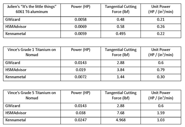
Feed rate (IPM), axial depth of cut (ADC), and radial depth of cut (RDC) are necessary to determine material removal rate (MRR = IPM X ADC X RDC). MRR and material type determine how much cutting power is required. Cutting Power = MRR X material’s unit power. Cutting power (HP) = Cutter Speed (RPM) X Cutter Torque (ft-lbf) / 5252. Cutting force (lbf) = cutter torque / cutter radius. Machine and workpiece force = Cutter force.
I plugged the information provided by @Julien and @Vince.Fab into the GWizard, HSMAdvisor, and Kennametal calculators to help understand and compare cutting powers and forces. Details are provided in the attachment and the results are summarized below. Due to the small values involved, neither Kennametal nor HSMAdvisor had enough displayed resolution to provide accurate results. So, as shown in the attachment, I used their highest resolution results to calculate the other results more accurately. I assumed that Julien was cutting 6061 T6 aluminum. Vince didn’t say which type of Titanium he was cutting, so I did calculations for both Grade 1 and Grade 5 (the most likely grade).
Note that, unlike the other calculators, GWizard did not adjust its calculations based on the selected Titanium alloy.