I have cut the attached file with the first rough and first finish cuts. I would like to change the depth of the next, 1/32" ball bit, to only drop down on the outside of the lion head no more than 1/4" as my bit only has a cut length of 1/4" and I don’t want to run into a problem with the 1/4" shank on the 1/32" bit.
Any way to do that, or am I even making sense???
Well just tried to load the file but it is to big. 9.3MB
I believe what your asking is your material stock is thicker then the design and you dont want it to cut all the way down to zero, you want a backer like?
If so when importing the .stl you should have the settings all come up you can set the base to x amount so it’ll only cut down to say .25 and do the 3D carve from the base height to the top of the material if that makes sense to you lol
The Base Height will just make the 3D object taller. It won’t add “runoff” to the sides.
If you only cut within the boundaries of the 3D object it won’t cut into your material.
(CC V751 creates a boundary for you)
But if you want a pocket with the 3D object embossed on a flat surface, you should create 2 3D objects. Make a rectangle that represents your background. Create a 3D component using that rectangle that is Flat, 0.25" in height. Then import the STL and add it on top of that background.
Now you can use the outer rectangle boundary to cut both the background & the 3D object.
Appreciate the responses.
I have the box/background set up and have a raised rough and finish cut leaving about a 1/2" standoff for the STL face. The challenge I have is that I have a 1/4" shank with a1/32" bit to do a final/final finish cut BUT the cut length of the bit is only 1/4". IF I use it, the width of the 1/4" bit will hit the sides of the raised STL face and through the router off setting of X/Y. Been there and done that and ruined a number of pieces before.
I’m trying to keep everything in place and just do a finish cut with the 1/32" bit, such that I only drop down on the side of the face, no more than 1/4" to avoid the bit hitting the side.
Does that make sense?
I know that when I’m doing a non-STL (this is my first STL file), I get the options in the model tab, to set ROUNDING and depth and SCALEING, but these don’t seem to show up with the STL load.
I’m just confused with it, but will keep trying.
It would help if you could share the file. Can you upload it to drop-box or google drive or something then share the link? Or at least post a picture or 2 of the model.
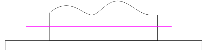
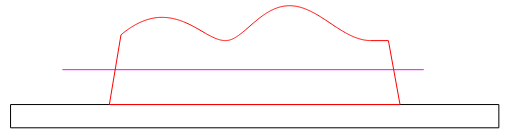
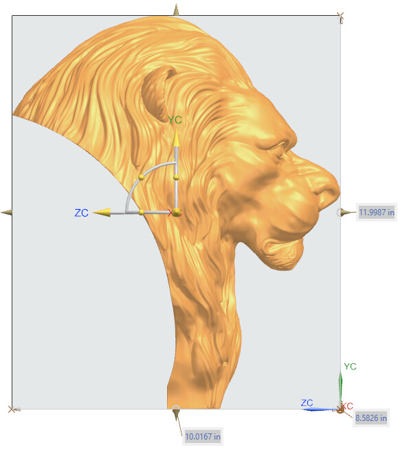
If I understand correctly, you have something like this, and want to limit the depth of the cut to the pink (1/4" deep) line??
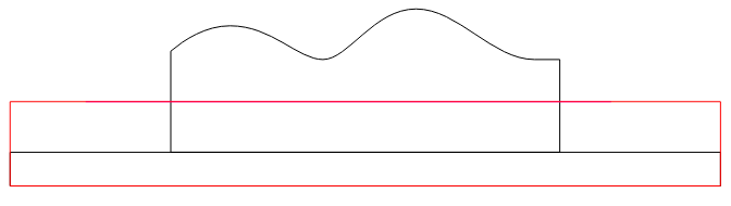
You could just build another component that comes to that height, and use the Equal merge type.
Another choice would be to angle the sides at an angle equal to or slightly greater than the taper on your tool.
Again, much thanks. I’m redoing the cut, throwing out the first one and I think I have it now. We will see after the new 4-5 hours.
I’ll either get back with success…or more questions.
Ok, this is where I’m at now.
First cut of lion head was a disaster so no photo…to embarassing.
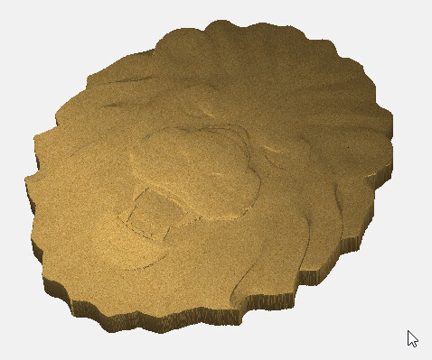
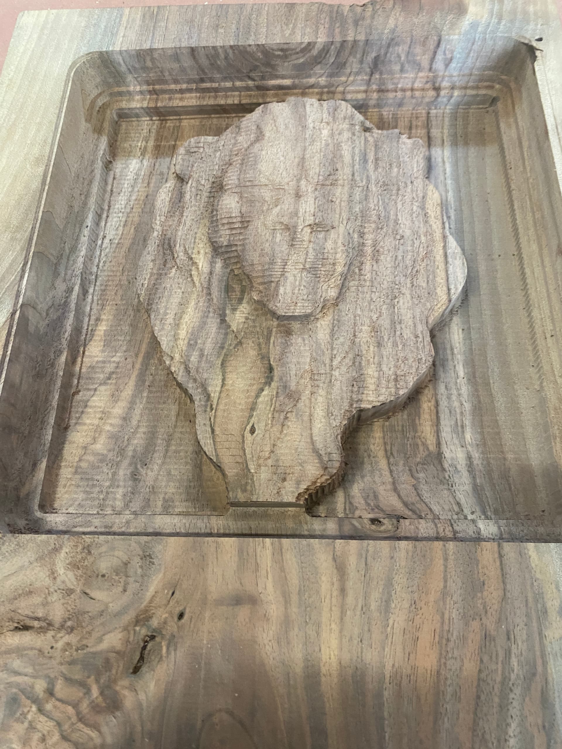
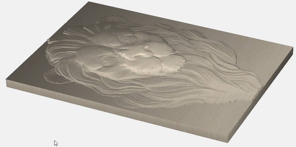
Second cut lion head pic is where I almost had a face of the lion, but the depth of cut was to deep for my 1/4" x 1/32 ball bit, but looked like I was getting at least some features of the face coming out. The second cut finished with a 1/8" bit.
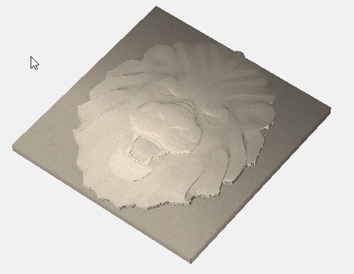
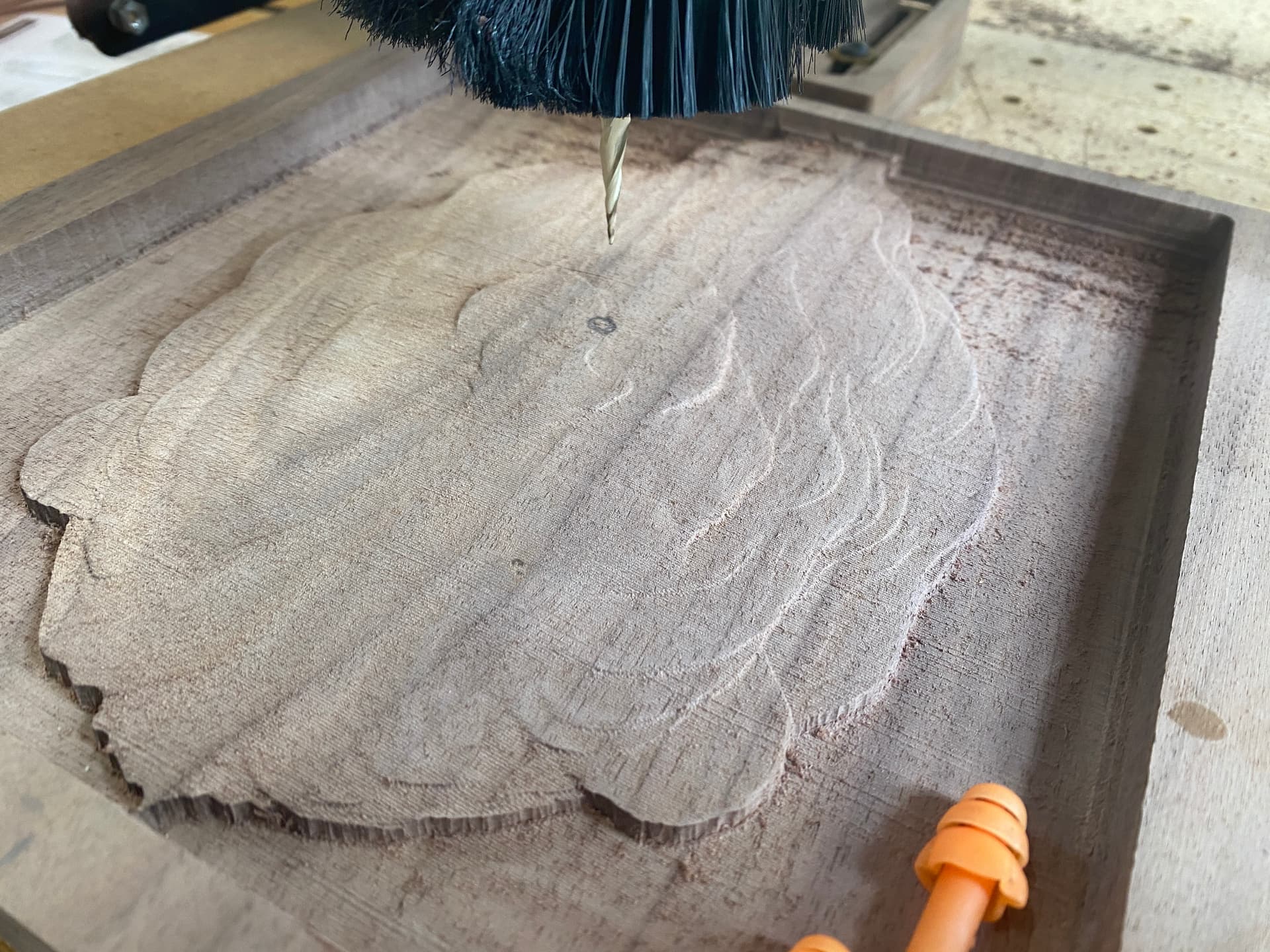
The third lion head pic, is where I shortened up the depth of cut so that my 1/32 bit would not hit against the outsides of the “frame”. While it worked without problem, there is no facial definition.
So…the question is How does one know from an STL, what the proper depth of cut is to get all the “facial features” of the design?? Is this just trial and error…which I seem to be pretty good at…at least the error side.
“Detail” is going to be factor of the ‘stepover’ in the finish path, and the resolution (height) you use when you import the STL. CC will scale the entire 3D object, even the bits on the backside that won’t be cut, so you are only cutting the top portion of the model. (Sent a PM to ask for the STL to analyze)
The “Detail” point I get. In fact, I’m using a 0.008 stepover with the 1/32" bit, so find detail from that standpoint should be ok.
Certainly the challenge is the height of cut. and it seems that it is just trial and error to find a height that gives the features of the face. Do I have to make lots of cutout samples until I find the “right” height or is there a clue somewhere that I’m missing??
Here is the link to the STL file I downloaded if that can tell us something.
You could probably calculate it by the height & scale that it wants to import at.
But if I scale the STL up to 12" tall, it’s 8.6" wide, and 10" deep. But at least 4" of that (behind the ears) is wasted & just causes your import to scale down further.
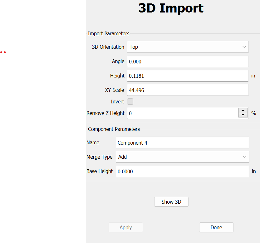
My bad, looks like the height defaults to 0.1181 no matter what size the STL is.
I guess the only way to know is if the author lists the size, or you open in a 3D software & measure it.
I measured a point just behind the back edge of the ears at 4.5" out of 10" from the back of the STL.
So that leaves 5.5" for the part I want to carve.
I can cheat, and define my material as 1" thick, and get 0.550 for the carved portion. So if my real stock is 0.750, I’ll have a 0.200 thick background.
Here my workpiece is 8.6 x 12 x 1". I created a flat component 0.45" thick, then imported the STL at 1" thick and used the Merge Type: Max. So the portion of the STL I don’t care about is buried in the background block.
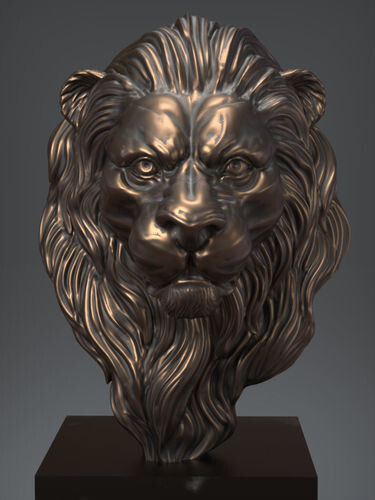
First off let me say I love it! That is the detail I’m trying to get to and maybe just a little more height/depth to showcase the face from the base.
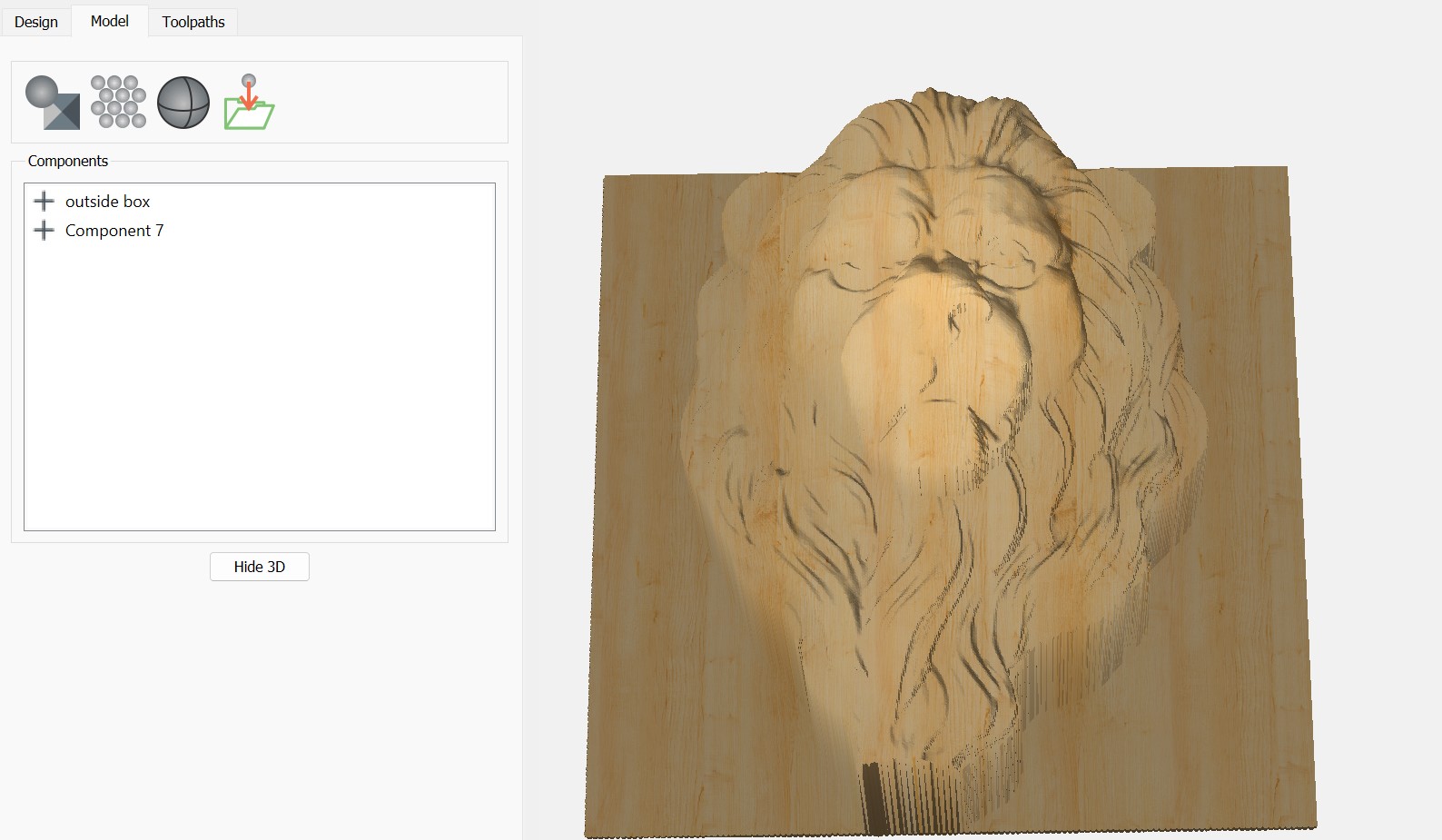
That said, I have no idea what you are saying as to how you got there. I do know that if I establish the material thickness as 6" and the depth of cut on the STL as 5.5" I get the detail I desire, at least in the model tab, per the attached.
However, when I do a rough and finish cut, even down to a 1/32" ball bit, the detail pic in the simulation does not get the same detail. I’m guessing that is because it is using the 3XXL spec and knows it can’t handle a 6" slab.
Any way you might break you explanation as to how you got to your simulation, in smaller bites that I might be able to follow? Sorry, I’m just trying to learn as fast as I can, and certainly appreciate your help.
I got it. Followed your description one step at a time and looks like I’m getting there.
Will try and cut again and see if it get the results I’m looking for.
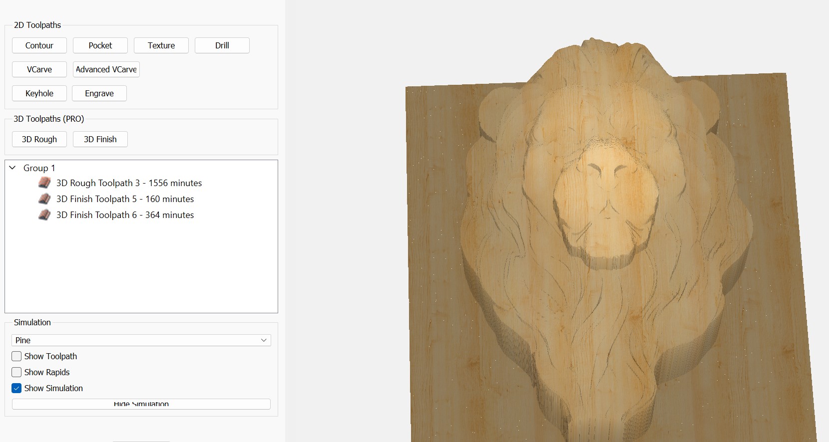
Maybe a should set up a different thread, but do you know if there is a way to make a material, like pine, a default setting everytime you load or start a project? Seems like mine always starts with cherry and while I use a lot of cherry, it is hard for me to make out features with it as opposed to pine.