I am using fusion 360 to draw the parts and for the G-Code. For some reason if I draw a 3" square with a hole in the middle and use a 3" square of aluminum. After I zero the piece of material with the probe and cut it the hole will not be in the middle of the 3" square of aluminum. It is always offset up on the Y and to the right on the X About .070. This makes double sided parts impossible to make. What am I missing ???
Maybe share your F360 file for a check ?
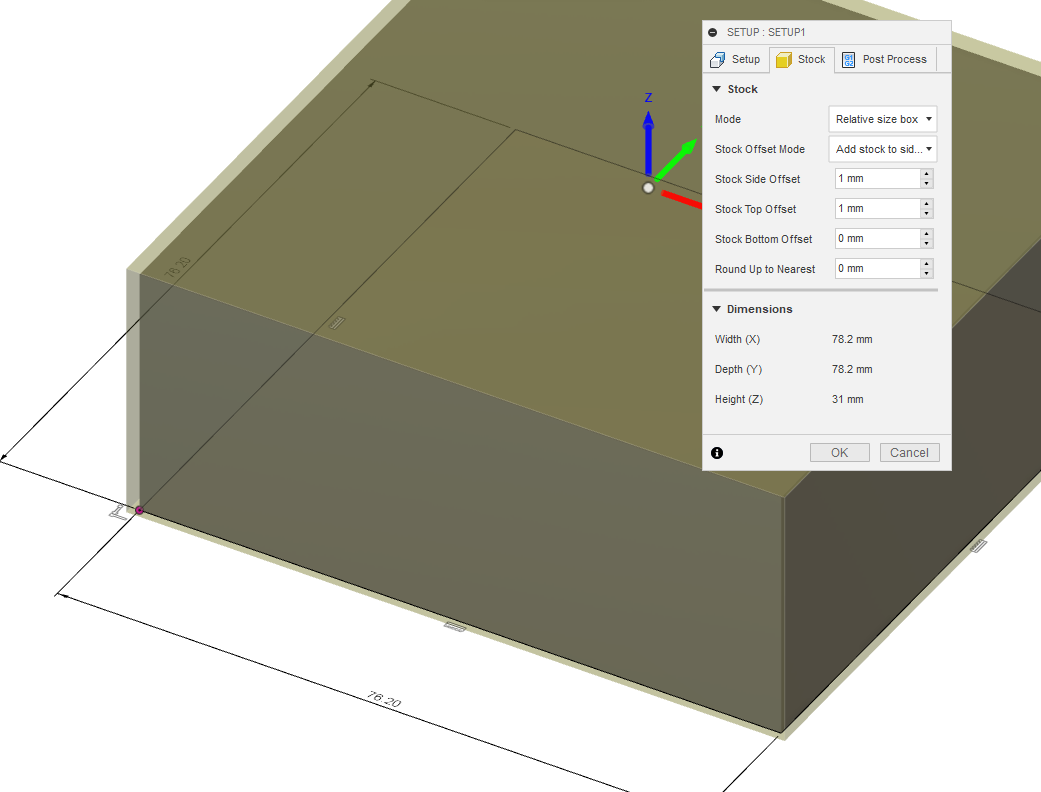
One possibility is that you declared the stock size to be slightly larger than the piece you designed, it’s easy to overlook especially since by default Fusion will create stock dimensions to be the dimensions of the piece PLUS a tiny offset, because it selects “Relative size box”:
EDIT: and I meant, you could then have declared you zero to the the top left node of the stock, which would not match the top left corner of your piece when zeroing
No the stock is entered as fixed size box for the 3" X 3" stock. Not relative size box
Have you calibrated for belt tension? Could be the steps are off by that much.
If all you are doing is making a hole in the center can set your origin to center instead? Not a great fix since it won’t help with more intricate designs.
1 Like
To check if it is calibration, zero in the corner, move up a bit, then jog 3" to the right and see where the endmill ends up…
2 Likes
it all checks out… Is there any software update for the fusion post processor program that is needed for carbide motion to read the g-code from fusion correctly… it seens like it is between fusion and carbide motion not the machine
What endmill are you using to probe? It could just be error introduced by using the endmill as a probe.
Try using a V-bit to eyeball zero… You should get a lot closer than .07" by eye (depending on the eyes, I guess).
3 Likes
This topic was automatically closed 30 days after the last reply. New replies are no longer allowed.