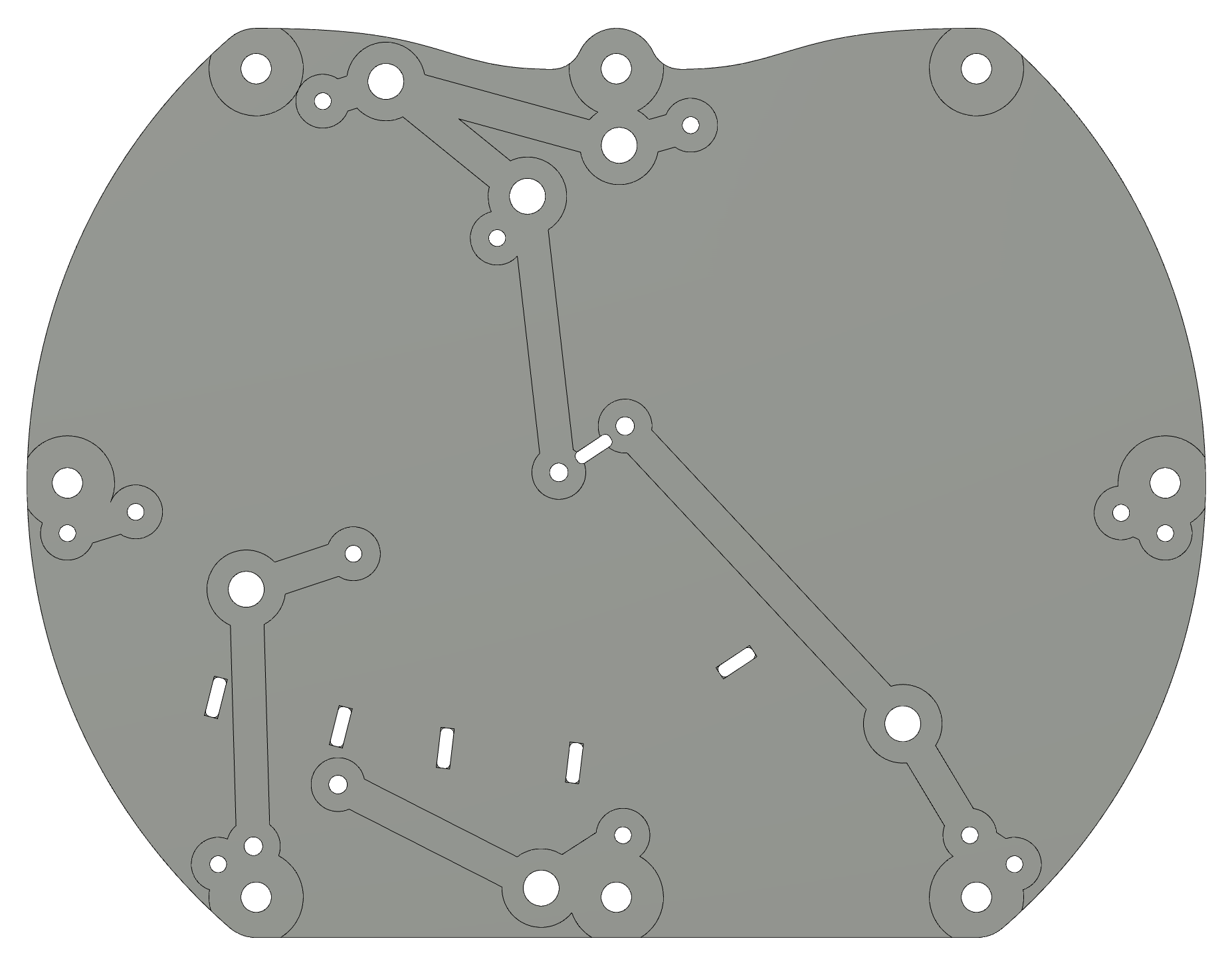
So as promised here are the details of the build. I’m working with a layout and the materials provided by a friend. He needed a one off board so I figured, hey, why not! The design was done by him in Fusion 360, and I did the CAM.
Material:
1/8" single side copper clad FR4 form Mcmaster link here
Tools:
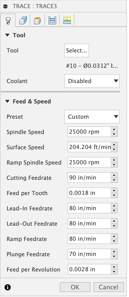
.03" ball engraver from lakeshore. you can find them here.
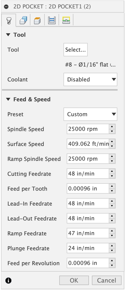
Slotting, holes, and part release were done with a 1/16" 2 flute from Kodiak.
Workholding:
Simple blue painters tape and superglue. That’s on a leveled waste board, shout out to @RichCournoyer for some good info on how to do it right! you can find it on this Post. But overall it’s ±.003" over the entire stock.
Speeds and feeds:
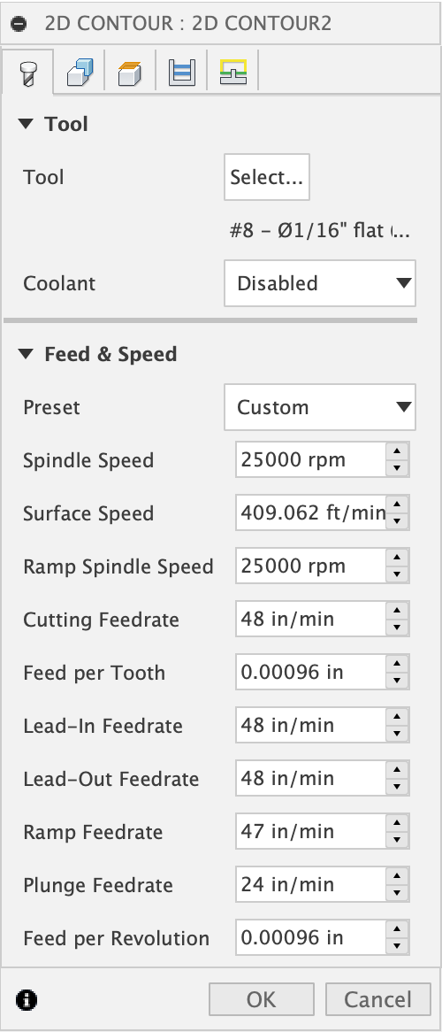
Did some digging around and I found a wide range of speeds and feeds. GWizard recommends high RPM and slow speed think 25000K and 12 IPM for the Kodiak. This seemed to run counter to everything I’ve heard about FR4. So I decided to stray from the course and go with high speed and highish feeds. The risk of course is rubbing and ware on the endmill, but since there’s so few cuts It’s a risk I’m willing to take. There were three Ops, a Trace for the…traces, a 2D pocket for the holes and slots, and a 2D Contour for releasing the part.
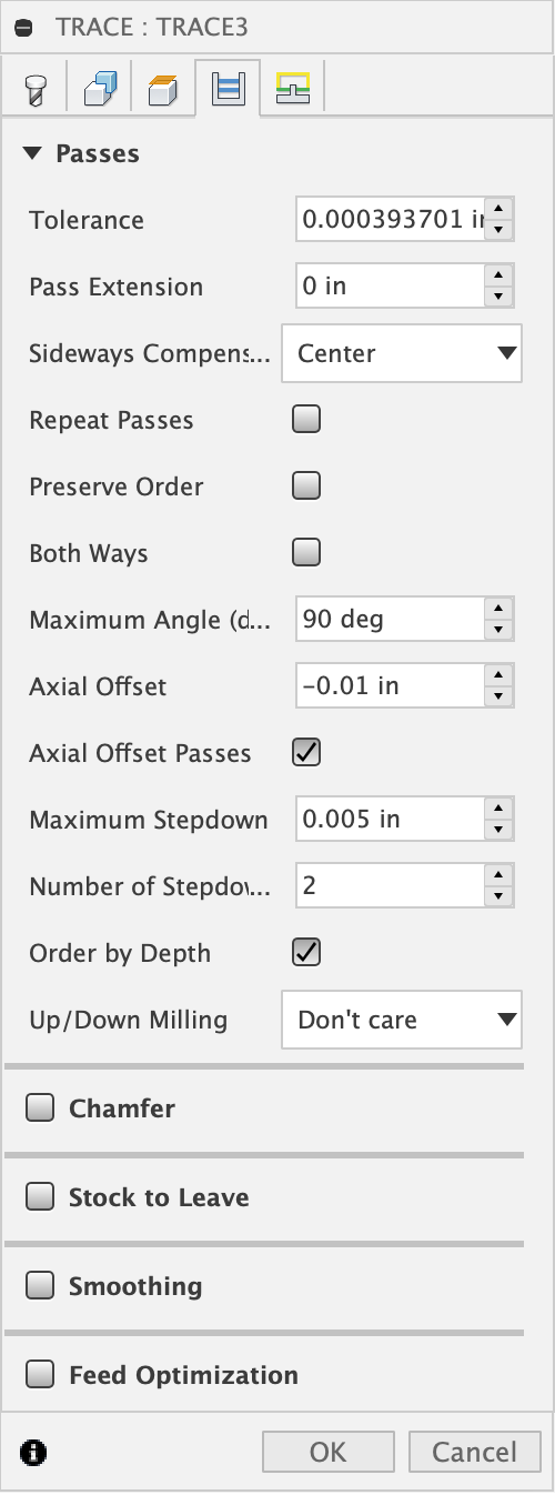
Trace:
2D Pocket:
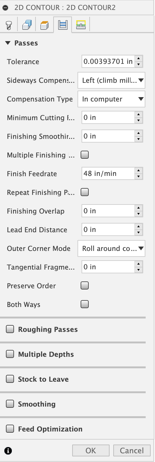
2D Contour:
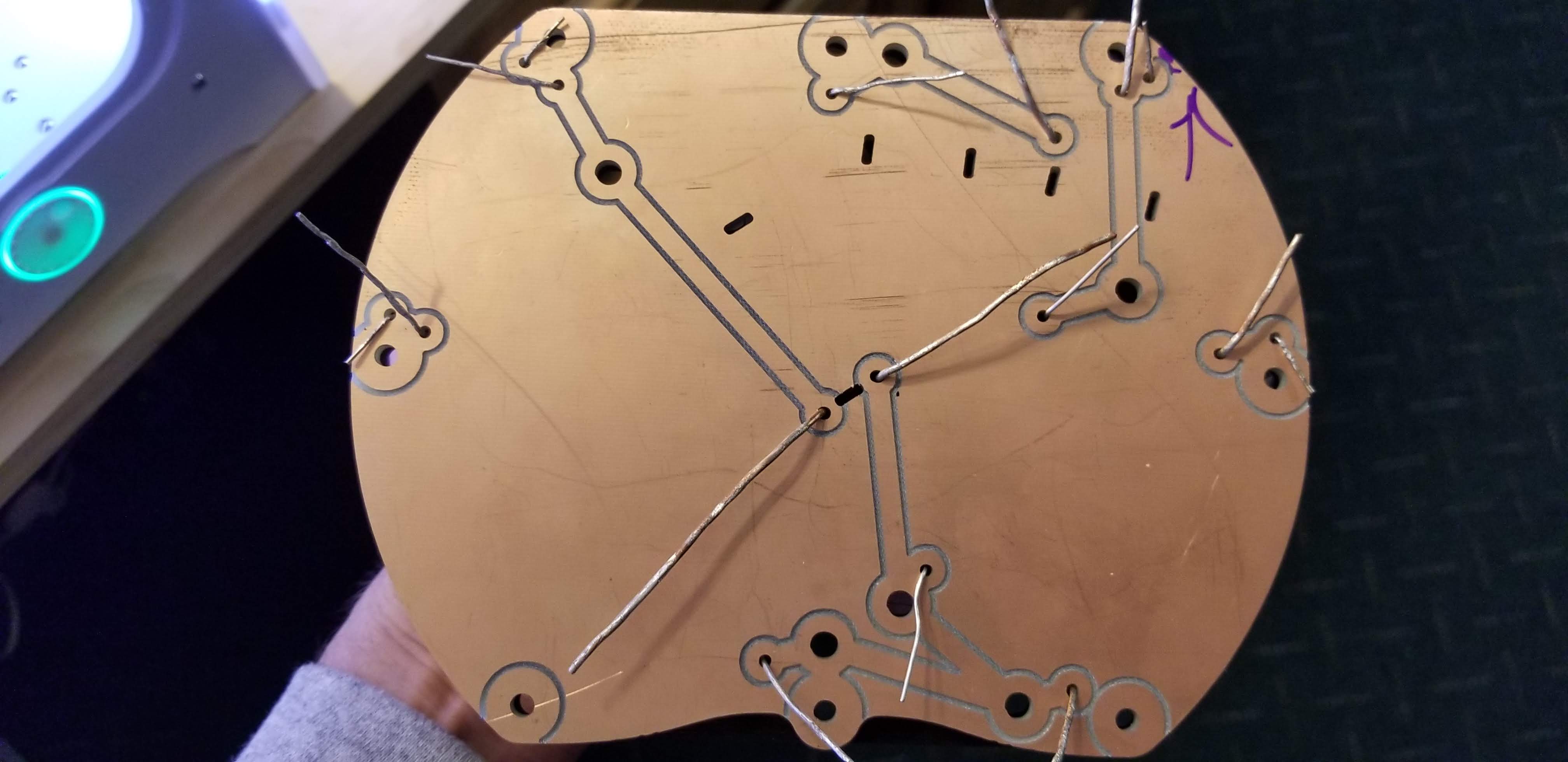
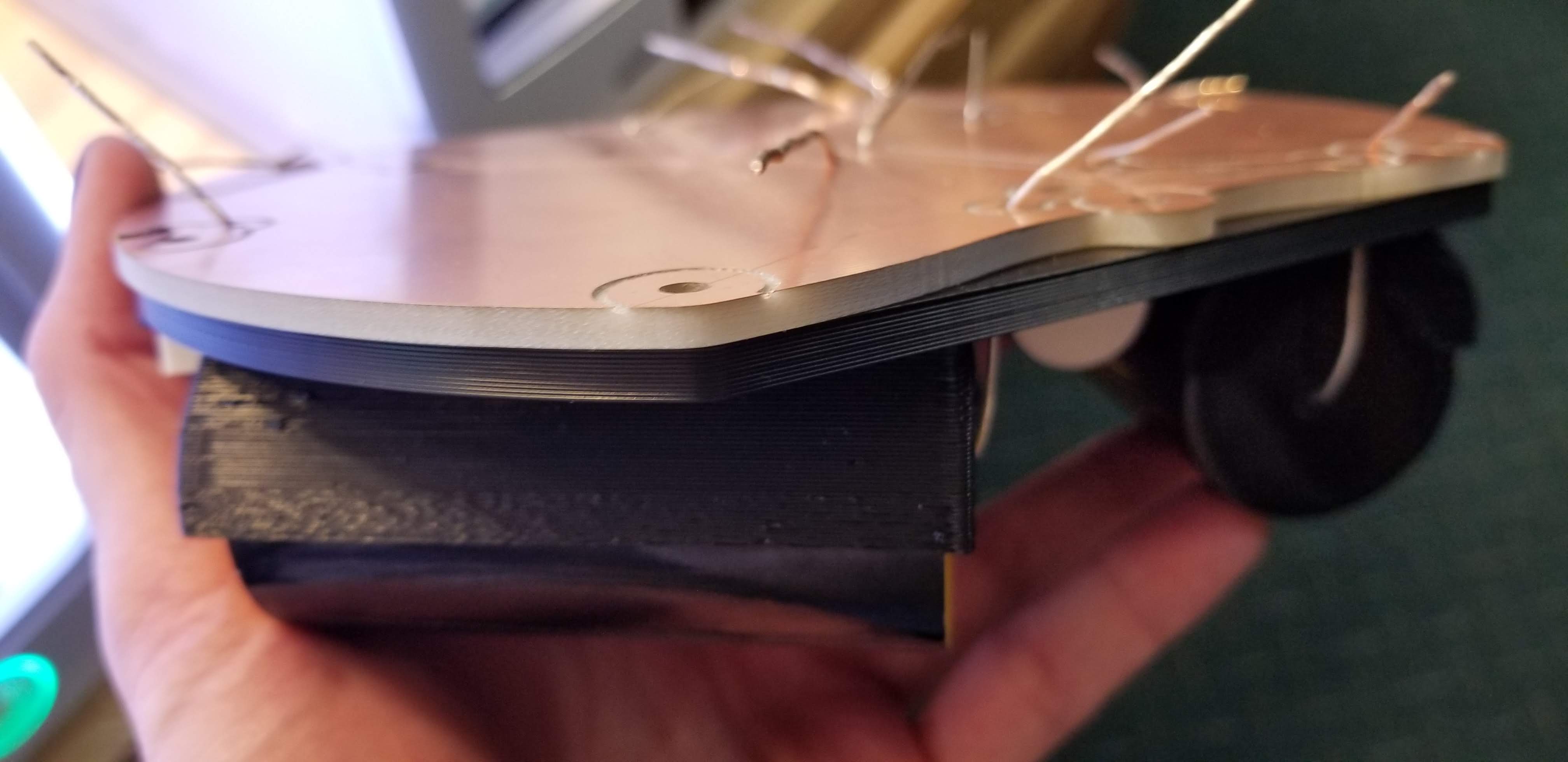
So with that out of the way here’s the results. Good clean finishes all the way around, and no damage to the copper. The only problem was buildup of the material in the cuts, although it wasn’t due to the flutes not clearing the material. The adhesive on the tape built up in the cut and created a slurry of fiberglass and tape. So I’d recommend a different pathing strategy or perhaps a different form of workholding. Another worthwhile note is the use of multiple passes on the engraving. I’ve found that it prevents rapid loading of the tool due to height variations in the board. So that’s it!
PS. If anyone knows how to fix the formatting on the pictures please let me know…