When I select more than one pocket in makercam, the same thing happens. If I am doing 0.10" step downs, and 0.50" total depth, it’ll cut the first pocket at 0.10" deep, then go to the second pocket and cut it to 0.10" deep, then go go the third. . .
It’ll work its way through all of the pockets at one depth before going back to the first and going to the next depth. That may be what is going on here. Unfortunately, if that is the case, you will have to select one hole at a time to get around that. Or bring a book and read while it cuts?
2 Likes
Griff
(Well crap, my hypometric precursor device is blown…)
4
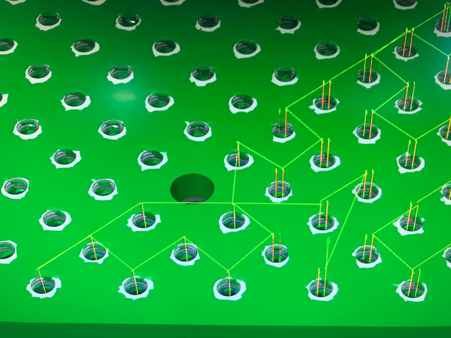
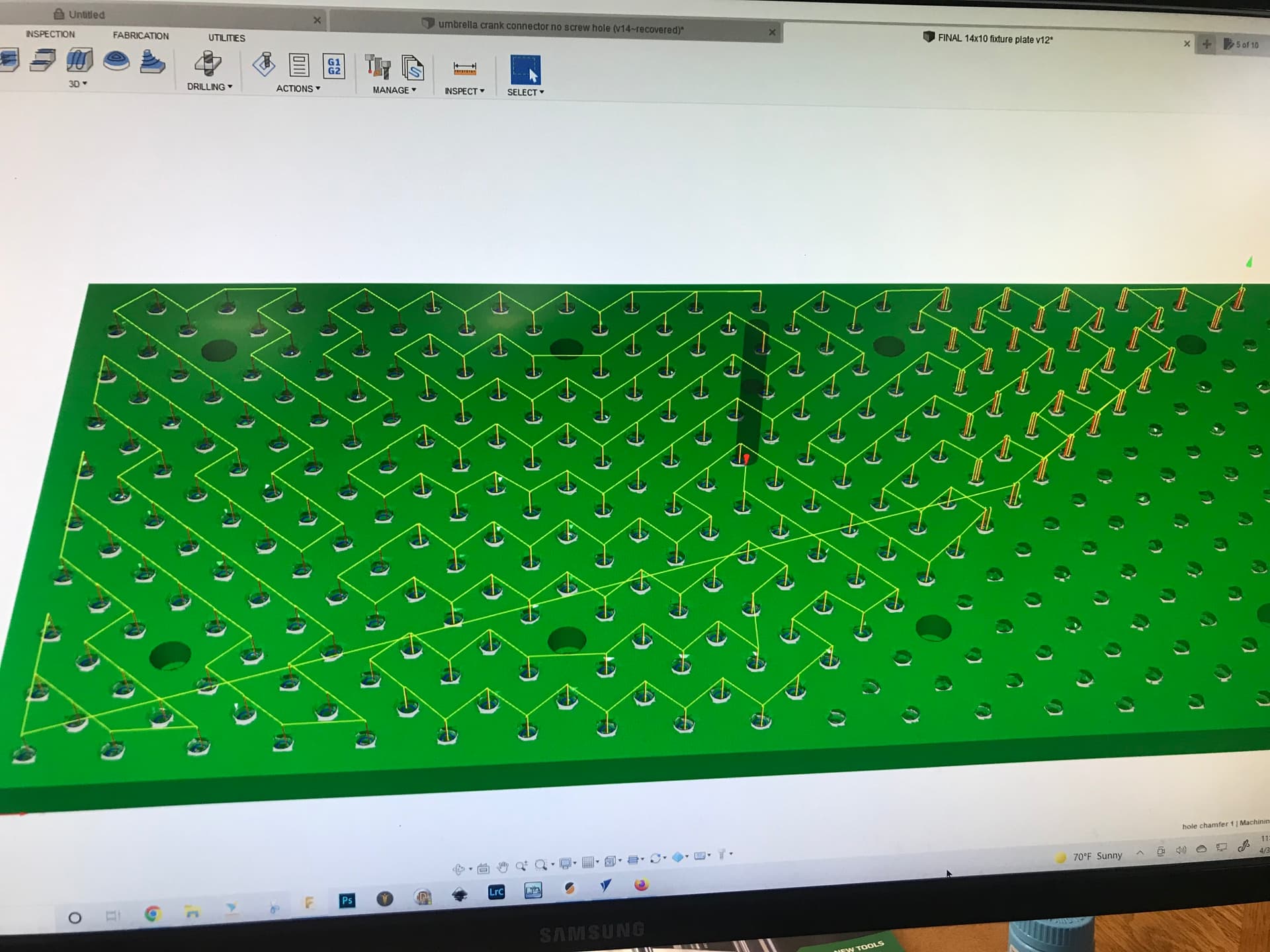
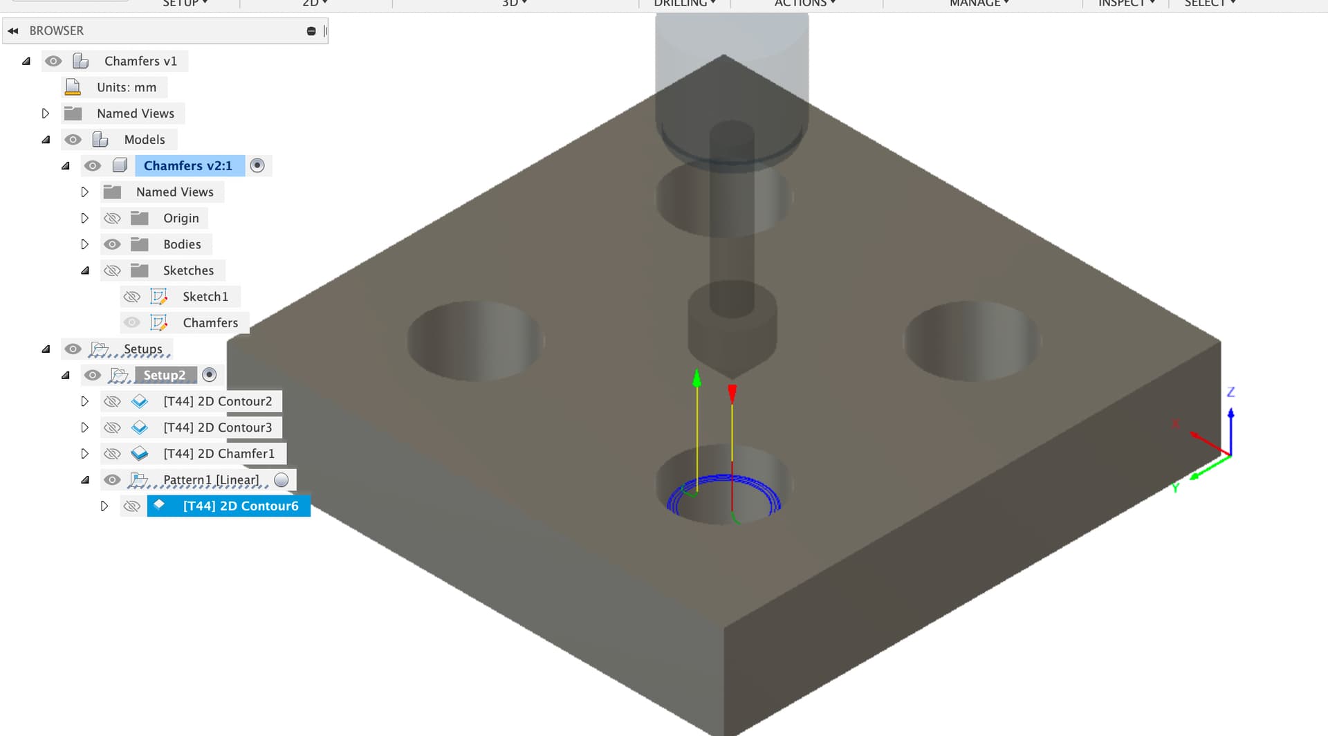
F360 chamfer toolpath. Each hole, groan, individually selected.
In that case I think MadHatter hit the nail on the head.
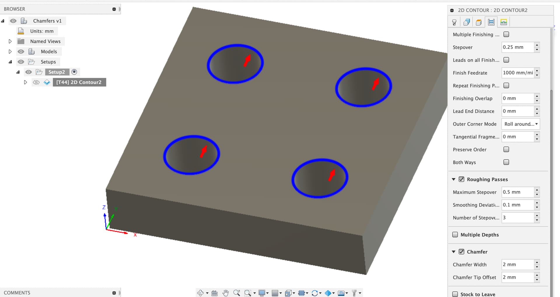
It’s a toolpath ordering issue, Fusion has a range of toolpaths you can use to do a chamfer, here’s a simple model where I’ve used the 2D contour with multiple stepovers to progressively cut a chamfer with a small finishing stepover, which is how I normally do these in metals.
Key thing here is that the contour is not modelled in the CAD (if I do model it then I suppress the feature before moving to CAM).
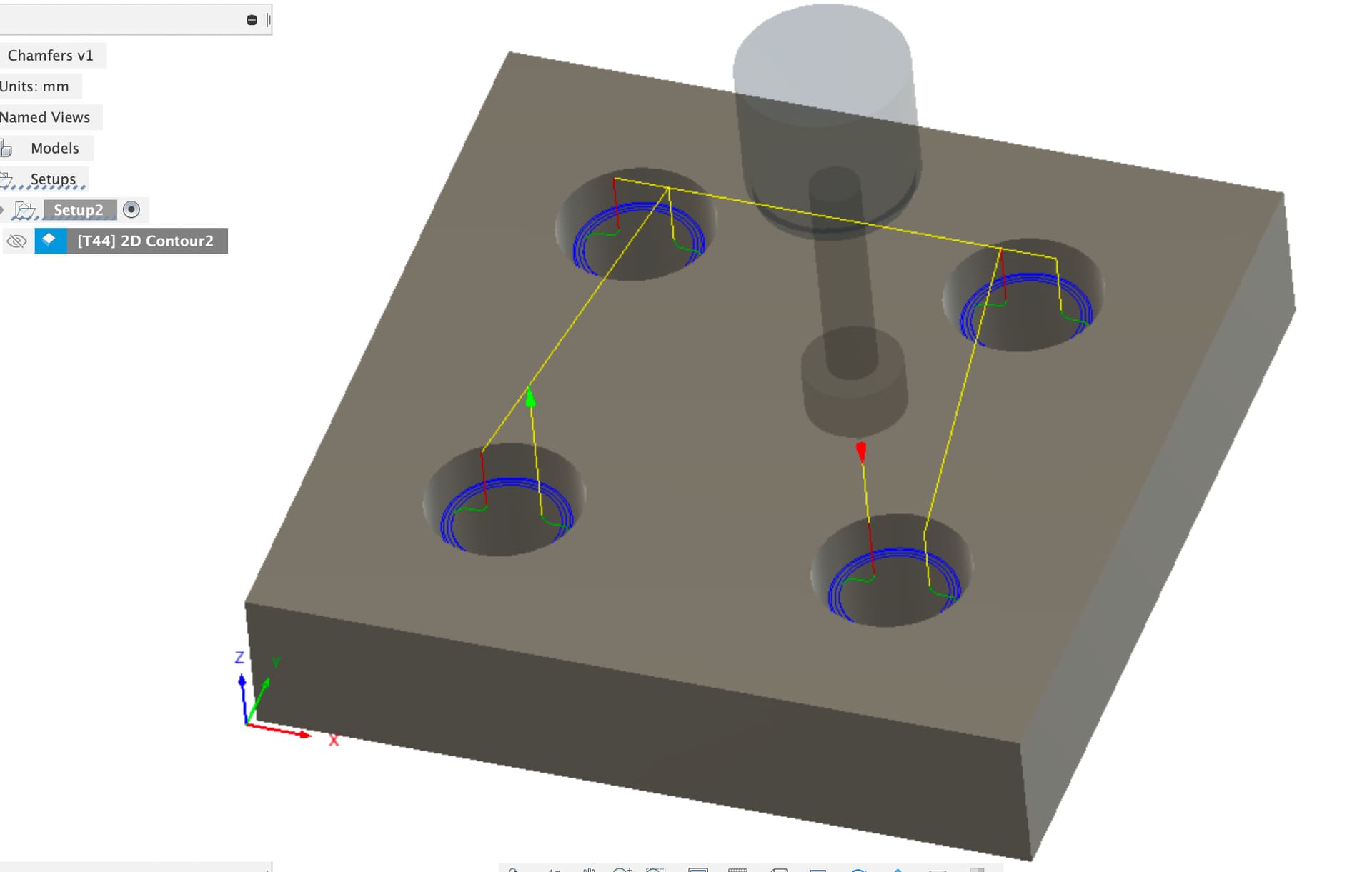
This 2D contour moves contour to contour doing the multiple passes in each location in order rather than depth order which the toolpath you’re using seems to favour.
Griff
(Well crap, my hypometric precursor device is blown…)
6
That is not what is happening here.
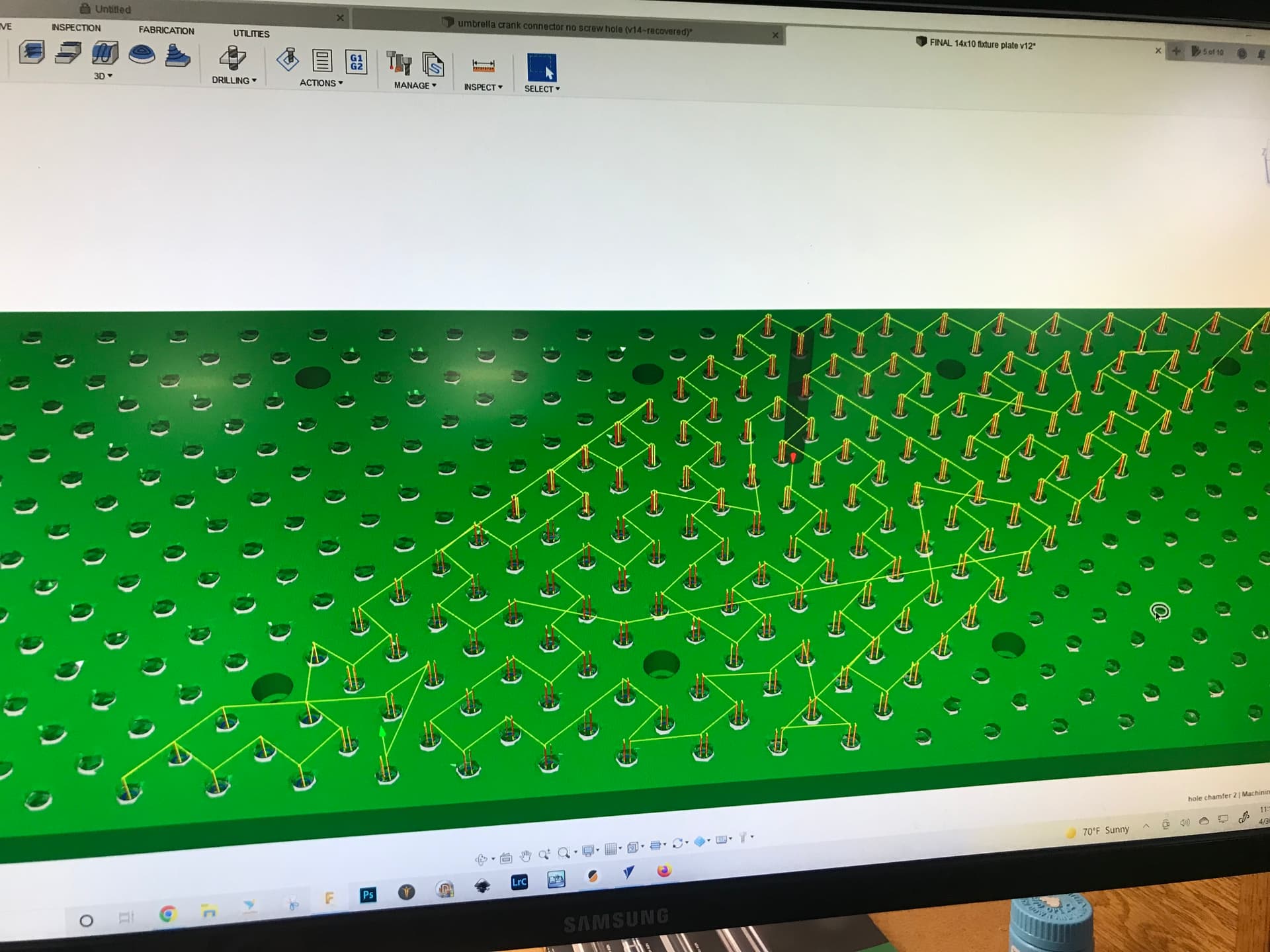
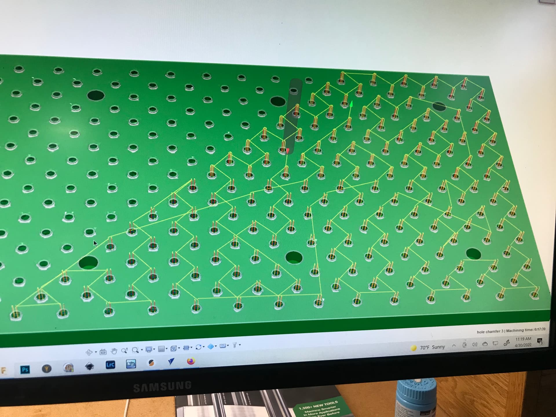
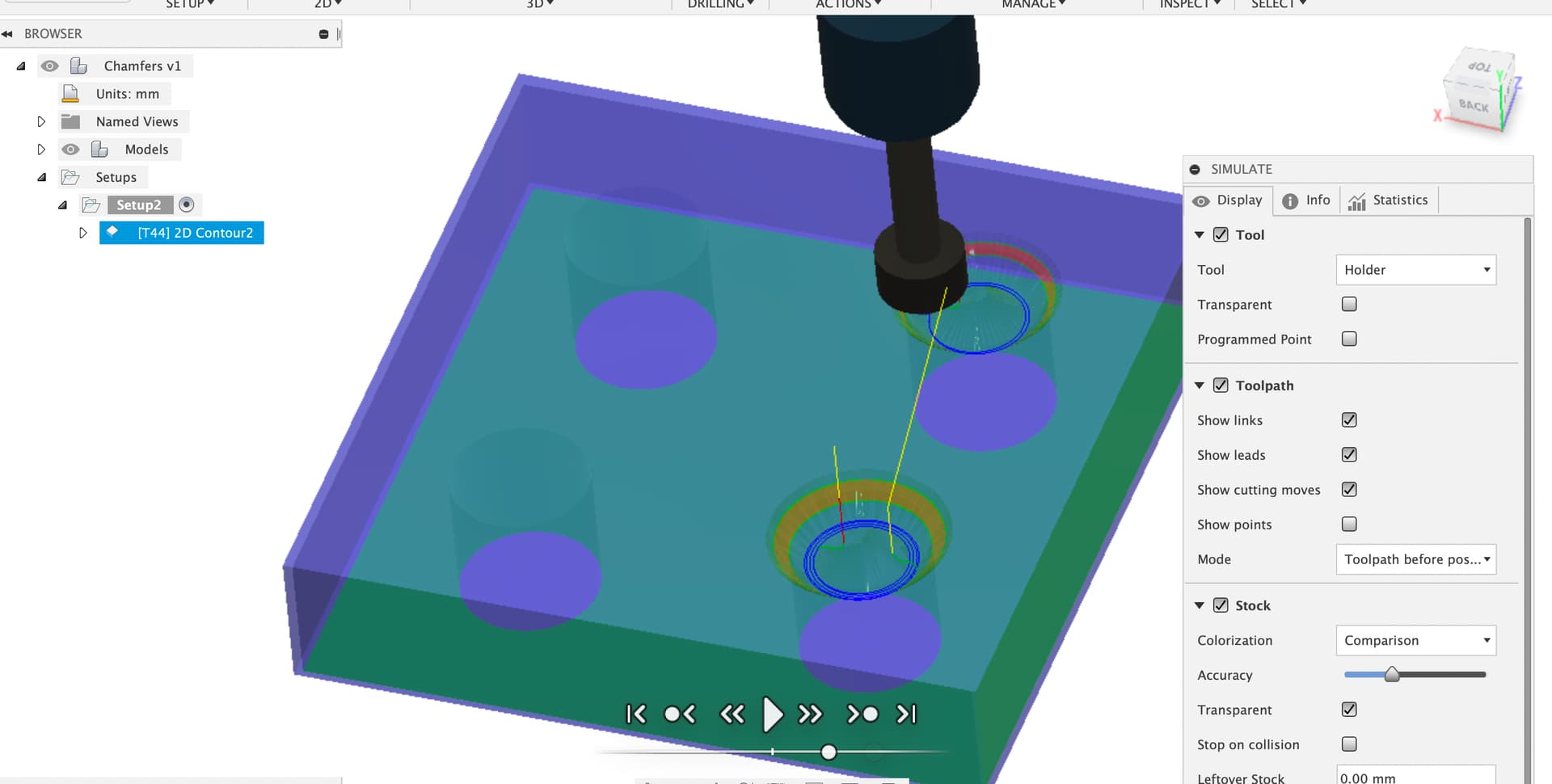
I individually select each contour (PITA), select 1mm wide chamfer in the chamfer toolpath. When the tool path runs you can see from the first pic that most of the contours complete at a single depth. Then they suddenly transition to three “pecks” to complete each contour. Depth of each “peck” is the same, distance around the diameter is what changes. So, each chamfer is complete when the spindle moves to the next.
Thanks Liam, I will check this out. I know there has to be a better way to cut a thousand chamfers that doesn’t require selecting a thousand contours!! Using a spot drill instead is one.
There’s a couple more options which might be worth trying.
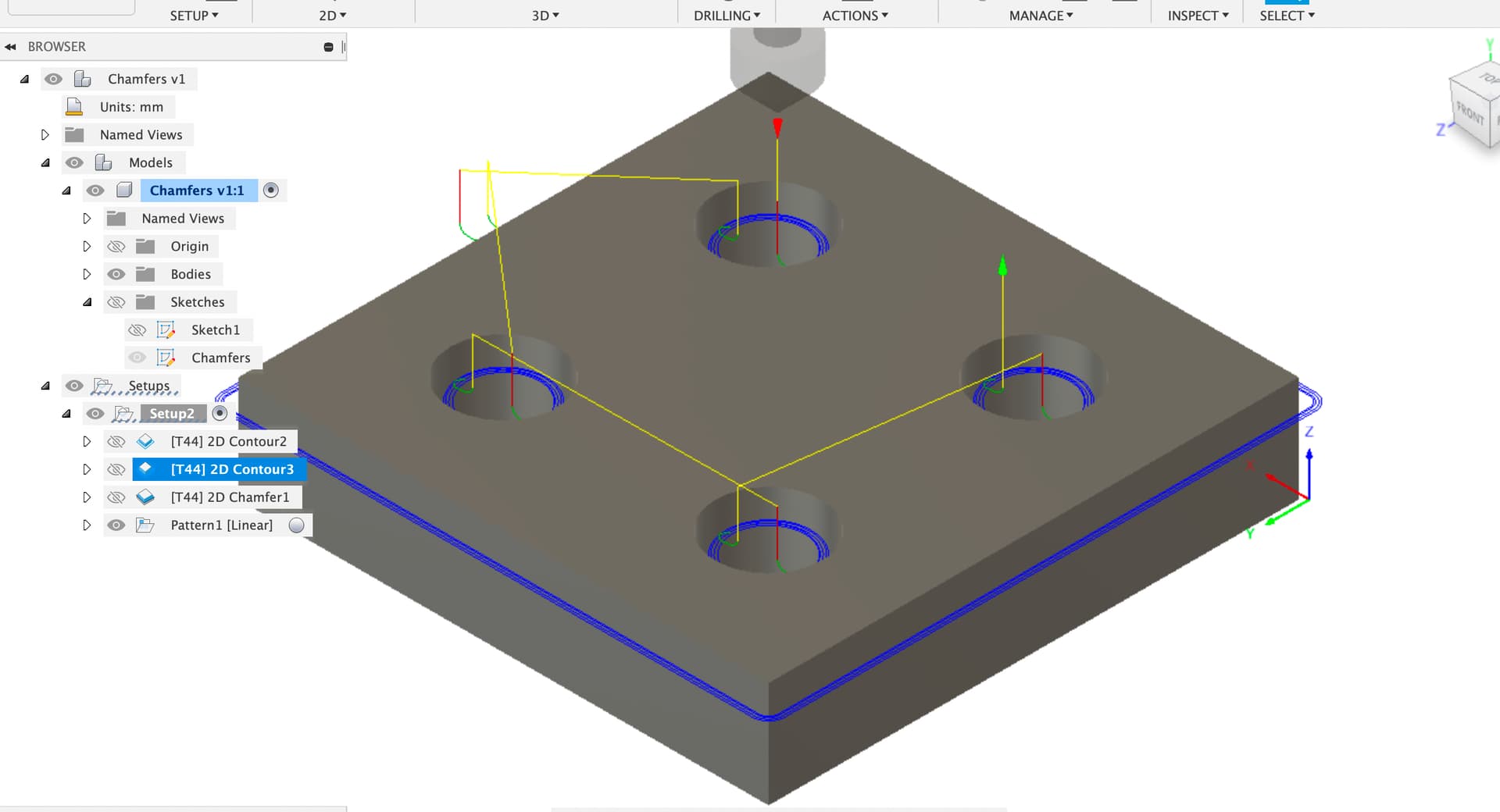
First, you can select a sketch as the ‘contour’ in many of the 2D operations, rather than selecting body edges. When you select the sketch Fusion tries to figure out how to do all the lines in the sketch as the contour. This sketch is just made on the top surface and the body projected into it.
This is a bit flaky, if you leave out the outer (as I did here) then it machines outside the holes, not inside. Allowing the full body to project gives a ‘working’ toolpath but we’re getting chamfers on the outer edges whether we want them or not. You could move the outer contour out but this is still smelly.
This should ensure that Fusion does the same thing n times rather than changing for some holes and not others.
1 Like
Griff
(Well crap, my hypometric precursor device is blown…)
9
I ordered it from 2L
2 Likes
Griff
(Well crap, my hypometric precursor device is blown…)
10
Now this is very helpful. No reason to model and then manually select each contour to chamfer. I was not aware of the pattern option within the tool pathing. Not surprising though as I use 0.1% of F360’s capabilities.
Thanks for the continuing education.
I still wonder about my original question about why F360 changed up the tool path from a continuous contour to a 3 part partial diameter cut?
a) Try reducing your tolerance for the chamfer toolpath. As in make it larger. Sometimes contours get chopped up if the precision is too high.
b) You really need to use patterns. Not only do you have fewer things to click on to select holes, but calculation times are faster. This is more important for things like adaptive toolpaths that take forever to calculate.
3 Likes
Griff
(Well crap, my hypometric precursor device is blown…)
12
Indeed. The reason I split the original path in three was because it took longer and longer to add a hole contour.
I’ve now added Patterns to my repertoire.
I just got my hands on my first 1/2" 90 degree chamfer tool for large chamfers and the thing is crazy heavy. The 1/2" tool has 4 times the amount of carbide as a 1/4" tool of the same length. If I ever damage it I could probably sell it back as a blank for a stub mill or use it as a missile .
I bet using a large spot drill is going to save you so much time on those hole chamfers. 1 peck and done.
I second the pattern option and I hope one day they add a suppress option to it where you can chose to ignore parts of the pattern like how the pattern tool can in the design work space.