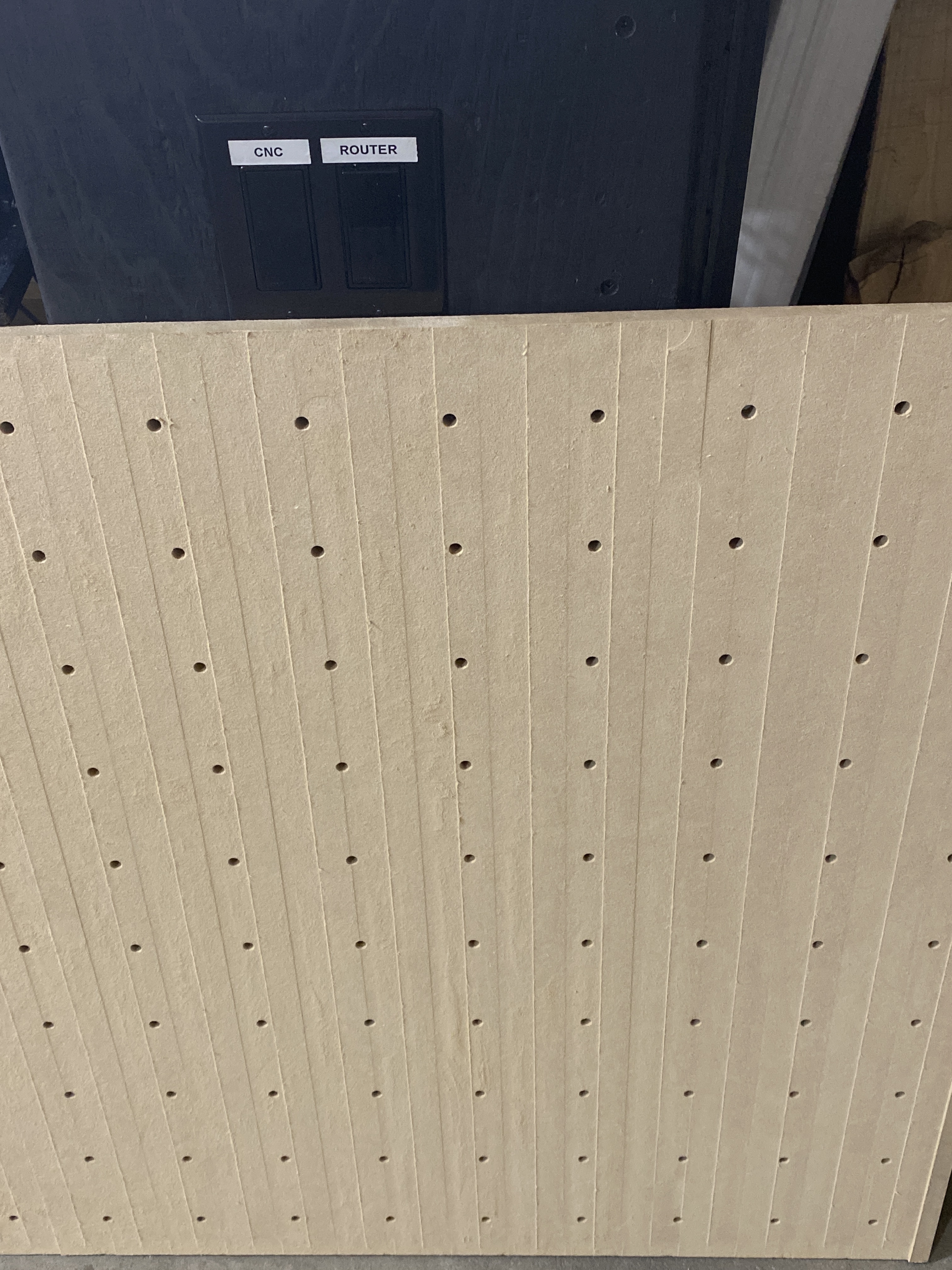
I’m surfacing my wasteboard and, I’m getting a strange pattern. I believe I need to tram based on my previous issues but I need help figuring how to tram for particular problem.
First issue is the zero axis. I have an nc file that set to 0.5mm and the file has been confirmed to be accurate by someone else. When I set my zero on the bit zero I end up getting a depth around 2mm. This makes no sense and I’m left to think I have a faulty bit zero? I did the paper method and it worked for zero but when I did it again with bit zero it dropped 2mm again. Bit is tight and marked with sharpie. It didn’t move.
Second issue for tramming. I have my tool path run vertical passes up and down. On the first up pass it looked normal but then as it came back down I could see a small line (enough I could get my finger nail in it) as it went back up it matched the down line perfect but then as it went down again it was not even anymore. Then again on the way up it matched the down pass. This repeated itself the entire wasteboard. I also noticed the north side was 0.25mm thinner then the bottom after I was able to measure with a set of calipers. As the passes got closer to the end they were less even period. I can’t see my router and z axis being that off. And the 2mm plunge is driving me nuts.
I would check that your grub screws are tight on all the pulley gears, and it looks like you are using a wide surfacing bit and you are badly in need of tramming. It really shows the wider the bit is. I use a dial indicator but there are other ways. You can get a pretty good idea using a 123 block how straight you are to the wasteboard.
Tramming I’m aware. Would you say it’s in need left right or front back? Also the grub screws on the pulleys? For the depth problem? Can you show me which screws you are referring too? Everything is tight and checked.
Grab and wiggle parts see if anything is loose. Check the V wheels for proper tension. The stepper motors have pulleys with teeth on them that sometimes come loose. They have 2 little tiny grub screws in them with Allen wrench heads. One of them should be locked into the flat part of the stepper motor shaft.
If you are losing steps on your Z up and down height, it could be loose grub screws or you might be skipping steps due to too much force being applied on your tool paths.
I think your stripes are front to back, that would be a left to right tramming issue that is making those lines. But it could be out front to back as well.
I purchased this gauge set to tram my machines: Gauges
You can make your own,
Winston has a very good video on how to tram your machine on Youtube.
I have seen people tram with do it yourself parts. Also can use a 123 block place it under your Z, use your fingers to twist the shaft till it is resting on the block. Check which side is crooked.
Very min step over to save time. If all is tram it shouldn’t matter but I’m definitely not squared to my wasteboard. It’s the deep plunge of 2mm that’s got me lost. It’s only supposed to be 0.5mm.
Everything is tight. Belts are tight, v wheels tight, nothing wiggles. Very level and square. Tramming is definitely needed I’m just lost on the z axis issue. Like I mentioned I zeroed with my bit zero and it plunged 2mm deep (1.5mm too much). If I set zero with paper method it works. It’s my bit zero that’s off and I don’t get why. It works for 1/4 bit for the holes and countersinking but when I switched out to 1” surfacing bit the zero isn’t accurate when I use the bit zero.
Does the large surfacing bit impact the Bit Zero plunger on a flat surface with no issues?
I know others had to work around the center of large surface bits not properly hitting the plunger on a flat spot.
I presume you have a BItZero v1… I’m not sure the hole in the BitZeroV2 is an inch wide… (maybe it is?)
Some surfacing bits are not totally flat on the bottom. If yours isn’t either, how are you lining up a 1" bit so that the very lowest portion of it touches the BitZero first, and when it does so, the BitZero doesn’t move or rock at all? Seems pretty tricky and easily a source of a 1.5mm error.
A bold prediction I will possibly eat later: something has to be loose.
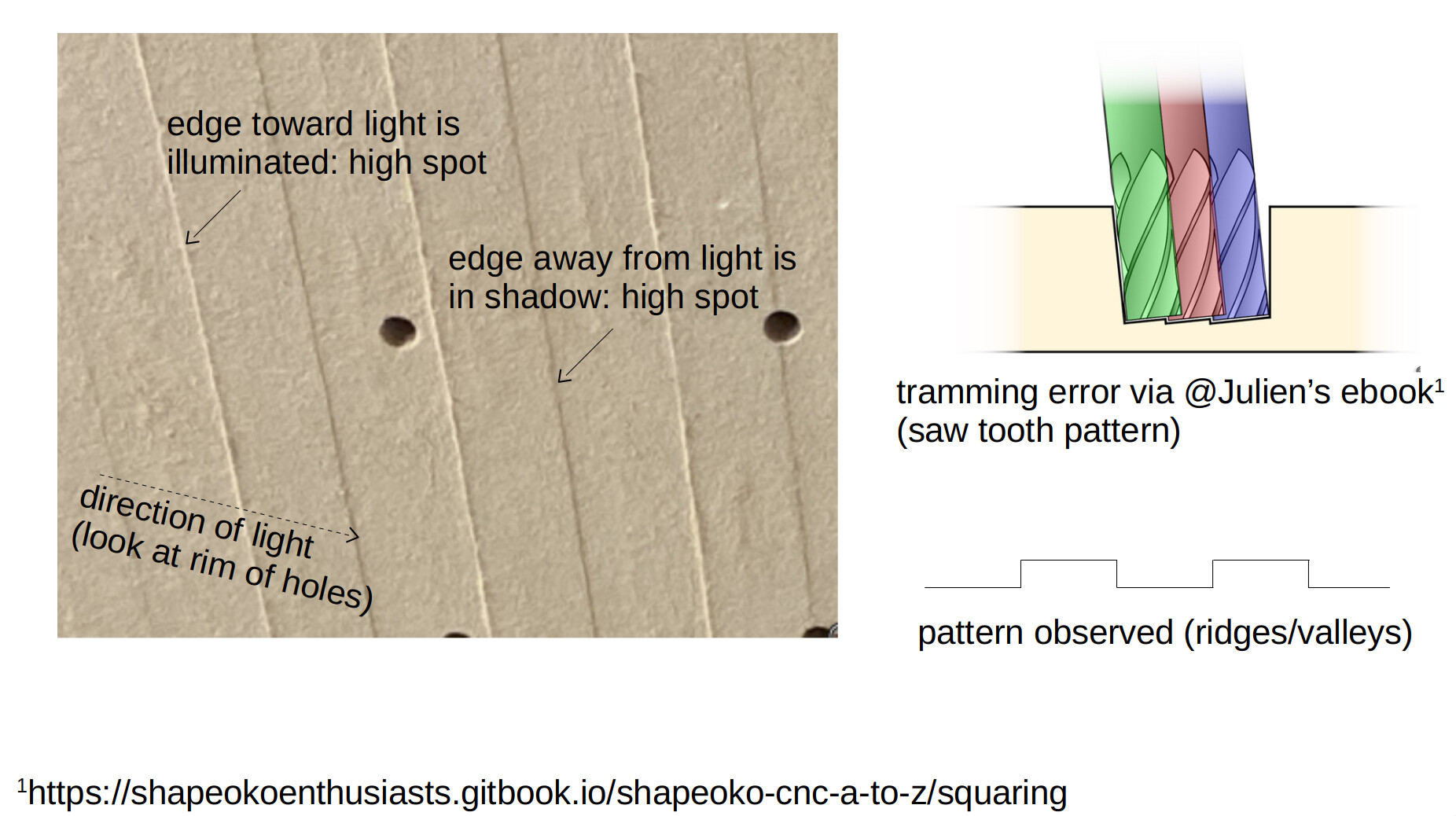
Look at the pattern of your cuts. It’s alternating ridges and valleys, not a saw tooth pattern that typically comes from tramming error. That’s what I see anyway. Here’s an illustration, with an excellent reference drawing from @Julien 's ebook.
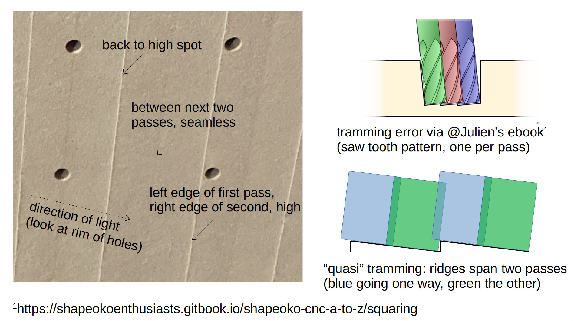
Looking at the right of your picture, you have what resembles tramming error (one side high), transitioning into the ridge/valley pattern as you go left. That said, note that the pattern spans two passes, which doesn’t make sense to me. Tramming comes from a fixed error in the router not being normal to the surface, so the bit should cut the sawtooth on each pass. In yours, the edges of two passes appear to create a seamless transition:
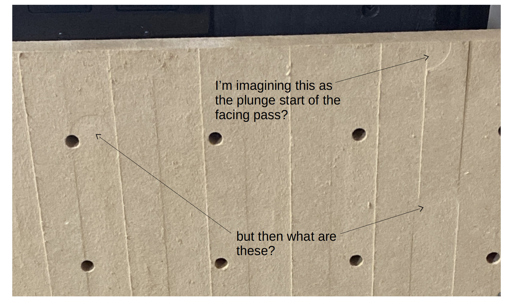
And for a final observation, note the “indents” in the board. Unless you were changing origins, this is absolute evidence of something shifting/getting “sucked down” mid pass:
Given this evidence, I envision that in addition to potential tramming error, something is also moving up/down as you traverse the wasteboard. I’m racking my brain on how this could arise from some weird combo of crazy tramming error and crazy out of parallel on the e.g. y rails, but am coming up empty at the moment.
For some things to check (I know it will feel like you’ve checked everything… just humor us ):
I found my z-axis carriage v-wheels were loose upon my first setup, probably because I forgot to go back and tighten them. With the machine on (Shapeoko motors, not the router) grab the router and just kind of pull it around a bit (left/right, back/forth, up/down). Do you see movement in the x/y belts or changes in z belt slack (like a “pucker/droop” that develops, or jiggle between the whole carriage and the x rail), or “clunks” (I had v-wheel that would rock back and forth due to an imprecise spacer once)?
can you rotate the router in the spindle mount?
facing the machine from the front, can you torque the spindle mount clockwise/ccw and get it to move (wondering if the spindle mount could be rotating on you as you go back and forth)
I’m pretty sure you should have better tramming results than this just by having used a square against the router mount or router body to the wasteboard; can you post a pic of that?
take measurements with a caliper (or decent ruler) from the wasteboard to the y rails at each of the corners, which should be a reasonable gauge for “the wasteboard plane is parallel to the plane the router moves in”
while facing, you could apply light pressure to the router mount up or down and see how easy it is to mess with the depth of cut. You’ll certainly see a change, and don’t shove on it, but I don’t think you should be able to move it whatever that ridge/valley offset is (can you measure that, btw?)
Obviously lots of guesses, but such is the game with a complex toy! Hope something in there is helpful.
Bit zero v2 doesn’t zero the Z axis in the hole. It zeros from the surface, which shouldn’t be an issue with the 1” bit. It hits flat and the second it touches it turns red and goes back up. By all accounts it’s zeroing correct but it plunges around 2mm instead of 0.5mm
I may have missed it in the earlier posts, but if you zero Z only make sure to have the BitZero placed fully on top of the stock, not overhanging the corner. I believe some versions of CM have a misleading illustration when probing Z only.
You sir are a fine gentleman! Thank you for such detailed response and help.
The random plunges and weird ridges was my error as I had stopped and started the machine a couple times trying different things.
As far as wiggle, movement, and slack. There really is none. My v wheels are tight. They spin but not freely, the belts snap like guitar strings. No shake no wiggles.
One thing that I noticed is that I seem to have z depth issues in 2 different ways. Let me explain:
I made my wasteboard in fusion 360, I created my holes with the boring tool path and set the depth to plunge 19.06mm at 1/4” passes. The mdf is 19.05mm (3/4”) so in theory the bit should have went 0.01mm through into the factory wasteboard. This didn’t happen. It was approximately 2mm short and didn’t go through all the way. The same nc file had a 1mm counter sink around as well but that tool path worked better. I used a 1/4 flat end mill. (201). Now since I had this tool path not go deep enough by approx 2mm and then the surfacing tool path go 2mm too deep there has to be a correlating issue. I’m just too new to understand what is happening. The tramming issue is understandable and since I’m using a 1” bit I know it shows way more when you have a tramming issue. I genuinely think my bit zero is off or something since I’m getting 2mm too deep on one tool path and 2mm not deep enough on others. I’m attaching my nc files for review to make sure I didn’t screw that up but I’ve been told they are fine. Possible the bit zero is wrong? Or still gotta be a z axis issue?
So the first thing to test is whether your zero is really zero.
Use a regular 1/4" bit and set zero on the spoilboard with the bitzero as you did before.
Now get a piece of paper and put it where the bitzero was and slowly jog down in Carbide Motion, use the Increment buttons to set your speeds down low and job down to zero, you should have pinned the piece of paper to the spoilboard. If you pin the paper early or late then you’re not getting a good zero from the bitsetter.
Now find a block of something and measure the height, say about an inch high, put that on the spoilboard with the paper on top, do the same, jog down and read off the zero when you pin the paper with the bit. This will tell you if the Z is moving the correct distance.
Once those tests are done it’s worth moving on to more complex possible issues.
Happy to help. Felt like fun detective work. I get what others are saying but… I would ditch the bitzero for now. Just one more thing in the loop, and your error is not only one of absolute z error, but of something else or you’d be flat.
Explicitly: the “channels” you’re getting in the left are not evidence of a z offset or tramming, but something else. You might just start with some scrap wood vs. the wasteboard. Clamp some piece of plywood or a simple chunk of 2x4 to the wasteboard and surface it with a 1/4 bit after manually zeroing. Maybe put it parallel with the y axis so you get many facing passes to look at the result. Just take something like 0.25mm. Is it flat, does it have “grooves” like your left most pic, or saw teeth (like tramming error)?
Edit: and could you markup that original pic with the sizes for reference? Like given a 1in bit, what are the widths between those cut lines we’re seeing? I’m trying to understand what I’m looking at with respect to where the bit was on each pass. Those are 1/2" wide (50% overlap)? Above you said “min step over” but I think you might have meant “max step over.”
This might be completetly irrelevant (and iI’ve had a long day) but is the wasteboard being properly held down and definitely not flexing during the cutting process?
Based on the directional nature of the errors, I would try to lift the bit (instead of lateral wiggling); if it does wiggle vertically then find what’s loose.
 ):
):