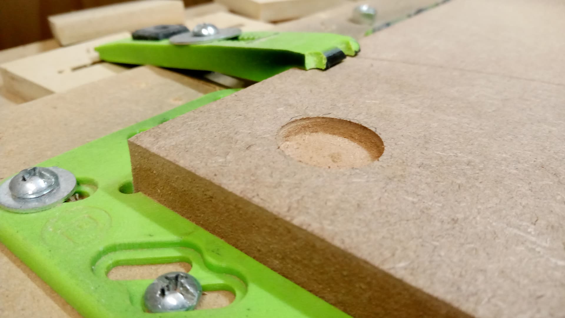
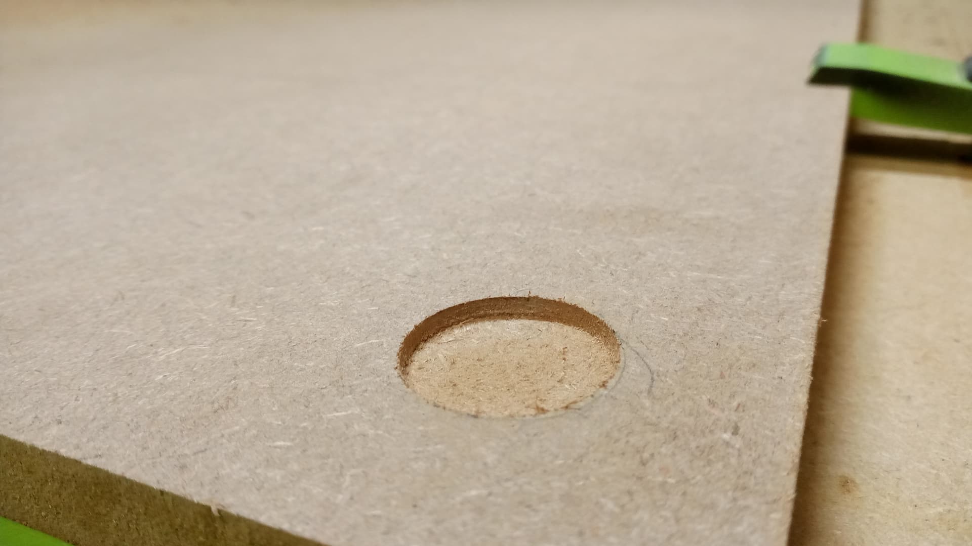
Hey guys, I’ve got a brand new, pretty darn flat of MDF yesterday. Threw it on the Shapeoko and wanted to pocket some shallow .2 depth pockets.
On the West side, you see the pocket went to the .2 depth, but when it comes over to the East side, I see it do the first pass in the air, second hits the material and the third is in the material but still does not make the .2 depth. I threw my Square and level on the shapeoko and my table and everything seems level and square…what could cause something like this?
Possible causes:
- lost steps — unlikely w/ a Z-Plus unless the dust shoe hit something or something is mechanically interfering
- uneven wasteboard — tram the MDF filler strips to ensure that they are all in plane w/ the gantry movement
1 Like
I don’t think my wasteboard is that bad, but…I guess I could plane it down and see what happens. I don’t have the means for the tramming process, I dont think. Dont you have to have some gauge or something for that?
I just bent a piece of rod and chucked it up, then swung it against a piece of leveled glass on the bed during assembly, then I marked all the slats w/ a pencil and flattened each slat w/ a separate toolpath, repeating until they had all be cut to the same depth and all the pencil marks were gone.
Would a gross test of level be jog to the left side of the work surface. Set the bit some distance from the top surface. Then jog to the right side. The distance from the surface top to the bit should be the same.
2 Likes
Yes, that would work — If you have a pair of precision rods, chuck one, then use the other as a go/no-go gauge by jogging the machine down, then lifting it up until the rod just barely clears it.
1 Like
You need to resurface your
.
1 Like
If you have the BitZero can you not connect the ground wire and instead of automatically “Probe” Z zero just manually lower the Z axis until the red light lights up and then manually set Z zero to the top of the Bit Zero in the first location. I’d also use the 0.025mm increments just before making contact with the Bit Zero. Then jog around and continue to manually lower the Z-axis (0.025mm increments prior to contact) until the red light appears on the Bit Zero and see what the Z value is in Carbide Motion. If the wasteboard is not level you’ll observe varying Z-values (not Z=0.000). Once one validates the spoilboard is flat/level to the gantry then I’d turn my attention to the stock as I’ve personally observed 1mm +/- .5mm on different materials from the store which I used to pretend was consistent thickness (other then rough cut lumber).
2 Likes
I just noticed that my Top Left Vwheel is spinning freely not sure how or why, but I wonder if that could have something to do with it? How do you tighten the top vwheels? I know the bottom ones have that special nut thing you have to turn, but what about the top?
It should work to loosen all the hardware, then push down and hold on each plate and re-tighten the hardware, then adjust the lower nuts:
Ok…tried that and it’s still spins freely
ok. Im uploading a video to send as well
This topic was automatically closed 30 days after the last reply. New replies are no longer allowed.