So I am a total newbie still. I have been doing some carving on some smaller detail pieces and I have been using smaller and smaller bits. i have a .024 for some small pocket stuff. As i want to get smaller than that, I have heard that I can use a v-bit for that. HUH? Really? I thought V-bits were only for V-carving. So my question is how do I set the depth of cut on a V-bit? If I am using A 30 degree bit do I set it as a pocket or a contour? Someone said the V bit wont go to deep enough to go across the dimensions of the carve. Is that what i mean? I guess basically, I want to cut a fine detail toolpath that wont go beyond the boundries I want to engrave.
So lets say I want to cut a shape, that is .01 wide. Can I use a 30 degree bit that is a .125 diameter? I guess I don’t understand. I try to set that toolpath in Create and the simulation appears that I am not cutting anything. Doesn’t even show the toolpath or movement.
Sorry for the long question, I feel I have made it to confusing.
so no a vbit is not smaller like that if you use it as a normal pocket or contour.
but if you vcarve the corner, the top of the corner will be “sharp”… just not all the way straight down… there’ the angle on the way down.
You can do an interesting hybrid but it;s not perfect: You can do an advanced vcarve (so main pocket with a flat bit, and then the vbit does the contour and the corners) followed by a inside contour of your normal flat bit. In all places where the flat bit can get to, it’ll be perfectly normal straight (90 degree or whatever you want to call it) but in corners… it won’t be, but the top of the corner will be sharp.
also note that most vbits are not “infinite small” in their point if you put them under a microscope… there’s a flat bottom at some level. they’re tiny. but almost never perfect… well at least the budget ones I end up buying.
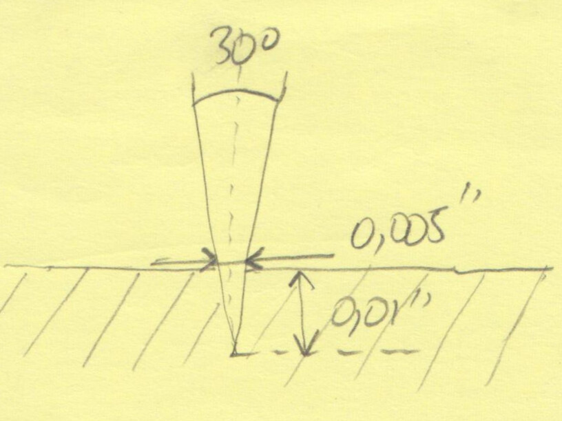
I’ll add that CC does not properly preview a contour cut when selecting a vbit as the tool, so this probably added to your confusion. But even though the preview is incorrect, the actual generated g-code is ok. So if for example you draw a circle, create contour toolpath using “no offset” for offset direction, select a vbit from the tool library, and enter a max depth of say, 0.01", you could run that and this would result in a cut that “engraves” the surface of the stock down to 0.01" depth, with your vbit. Which if you are using a 30° vbit, would actually leave you with a v groove that is 0.005" wide
Theoretically you can engrave an arbitrarily narrow groove by reducing the depth of cut, but as @fenrus noted in practice all vbit have a limit to how pointy they are at the tip. Also, the cut will be more and more sensitive to uneven stock surface, so it will become increasingly difficult to get an even depth across a large area.
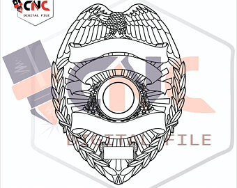
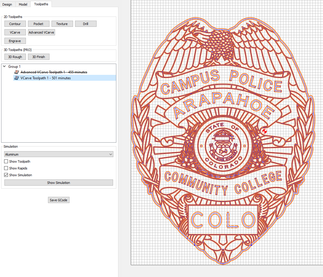
So lets say I want to engrave something like this. all those fine lines in the eagles wings. Would I use a v-bit and just set the depth super low? or would I use an end mill? This isn’t what I want to carve, but it’s a good example of what I am asking.
Advanced v-carving is interesting in that you can limit how deep the vcarve toolpath operation is going to go regardless of the selected vectors.
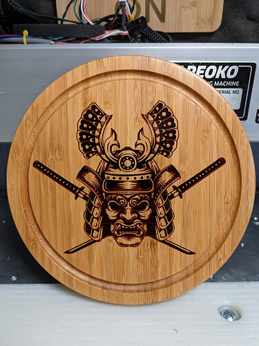
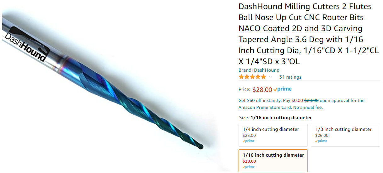
With a 20 to 30° vbit, one can carve pretty fine details. I keep illustrating this with my favorite v-carved piece so far, apologies to those who can’t stand seeing it being posted again and again
I used a 25° vbit, and then black epoxy to fill the grooves
BUT, and this is paramount, the quality of the result is directly linked to the quality of the input image. You will need a vector image, not a bitmap image. If you can get a vector version (svg, dxf) of what you want to engrave, it’s all good and you will just need to inspect the vector file at high zoom levels to make sure it has clean curves all around. If you only have a bitmap image, things get a bit harder: you will need to convert the bitmap image into a vector. There is an “image tracing” feature in CC that will let you do just that, but the results of the conversion depend on the quality and constrast of the input image.
Regarding the example you posted: I believe the grey & orange “CNC” part in the background is just a watermark, so if the file you actually got once purchased was the black part only, image tracing should work ok. And you could maybe get the vector source file itself ? (I often go to Etsy and search for svg files, and purchase them to use as a base for my vcarving jobs)
Once you get a clean vector file, you should be able to create a v-carve toolpath that cuts inside the black lines, and with a small angle v-bit, it may produce the level of detail you are after.
Julien, The image I posted was exactly as you stated. I just copied an image from etsy to use an an example. So, if I understand you, given that the image is an actual SVG without the watermark, I could carve that as a V-carve, or advanced V-Carve? I suppose I could just experiment to find out, but that would likely end this nice conversation.
Yes, given a clean SVG file, you should be able to use the vector for a vcarve toolpath, if it has lots of closed vectors. If it is made of open vectors, you could still create “contour” toolpaths with “no offset” option, for a single-line engraving.
A regular v-carve toolpath will do if all of the closed vectors are narrow enough that it is never wider than the vbit max diameter.
If there are larger closed areas, that’s when advanced v-carve is needed: it will then v-carve along the edges, but pocket out the middle of the area for a flat bottom at the specified max depth.
It’s hard to provide definitive answers though as the “v-carveability” of a vector really depends on its content/design.
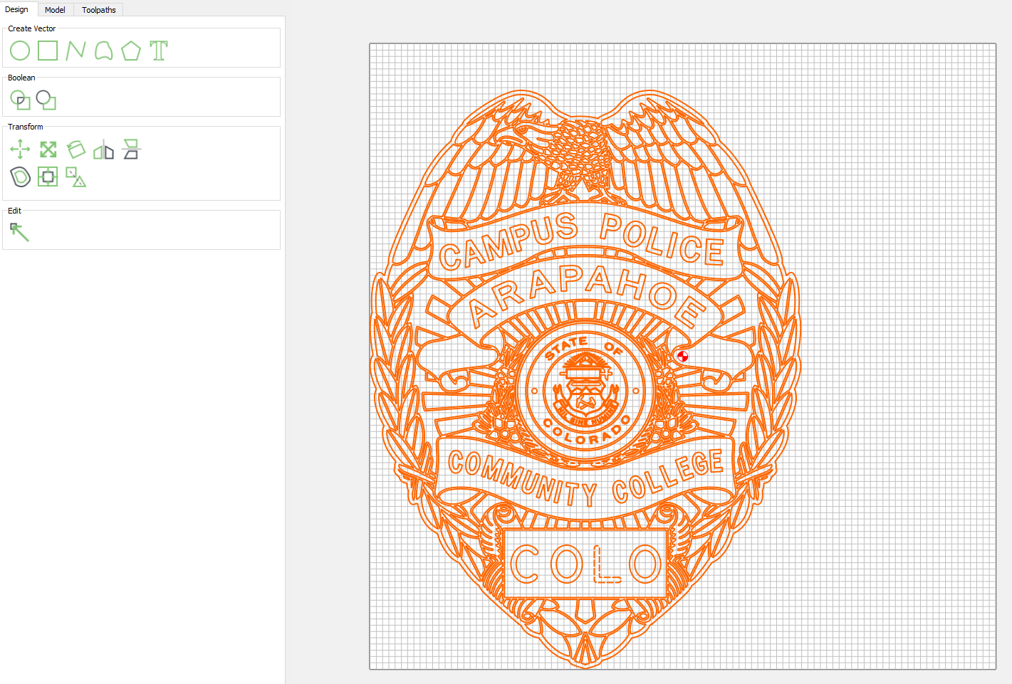
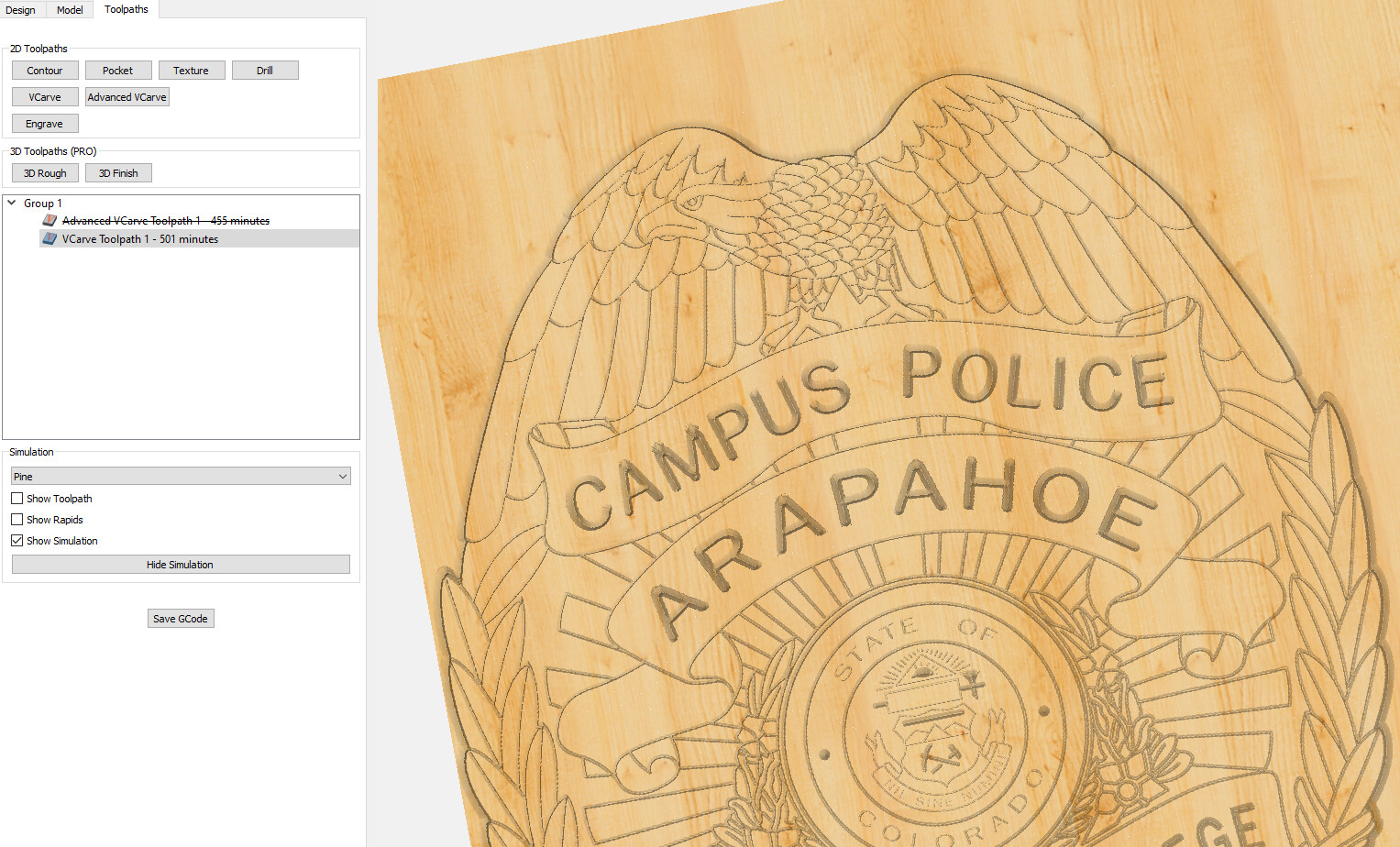
Googling around led me to find a vector version of (a variant of) that image, which I imported in CC,
For a regular vcarve, when no feature is wider than the tool diameter, “max depth” only matters if it is shallower than where the vbit would have gone if not limited. I did not even pay attention when I generated those screenshots, it had it set at 0.25", which essentially meant that the toolpath went as deep as it needed for the sides of the vbit to “touch” the sides of the closed vectors (which is shallow than 0.25", everywhere, so my max depth was not useful in this case)
Yes I have read through some of it. Honestly I am so new to all this, much of it doesn’t click for me. I am more of a hands on learner. If I can do it once or twice, I am good to go. Thank you for all your help.