Power-strip-mount

This WAS going to be for the current challenge (“I have one word for you- plastic”), but material supply got in my way. I can’t use a low surface energy plastic, and that is all I have on hand, and I am waiting (and waiting) for an order from over a week ago to show from less that 15 minutes away. So, I got it done with a finish grade BC plywood. Plywood is basically plastic. What? no? ok, then. This is just a project.

Banged this out in about an hour.

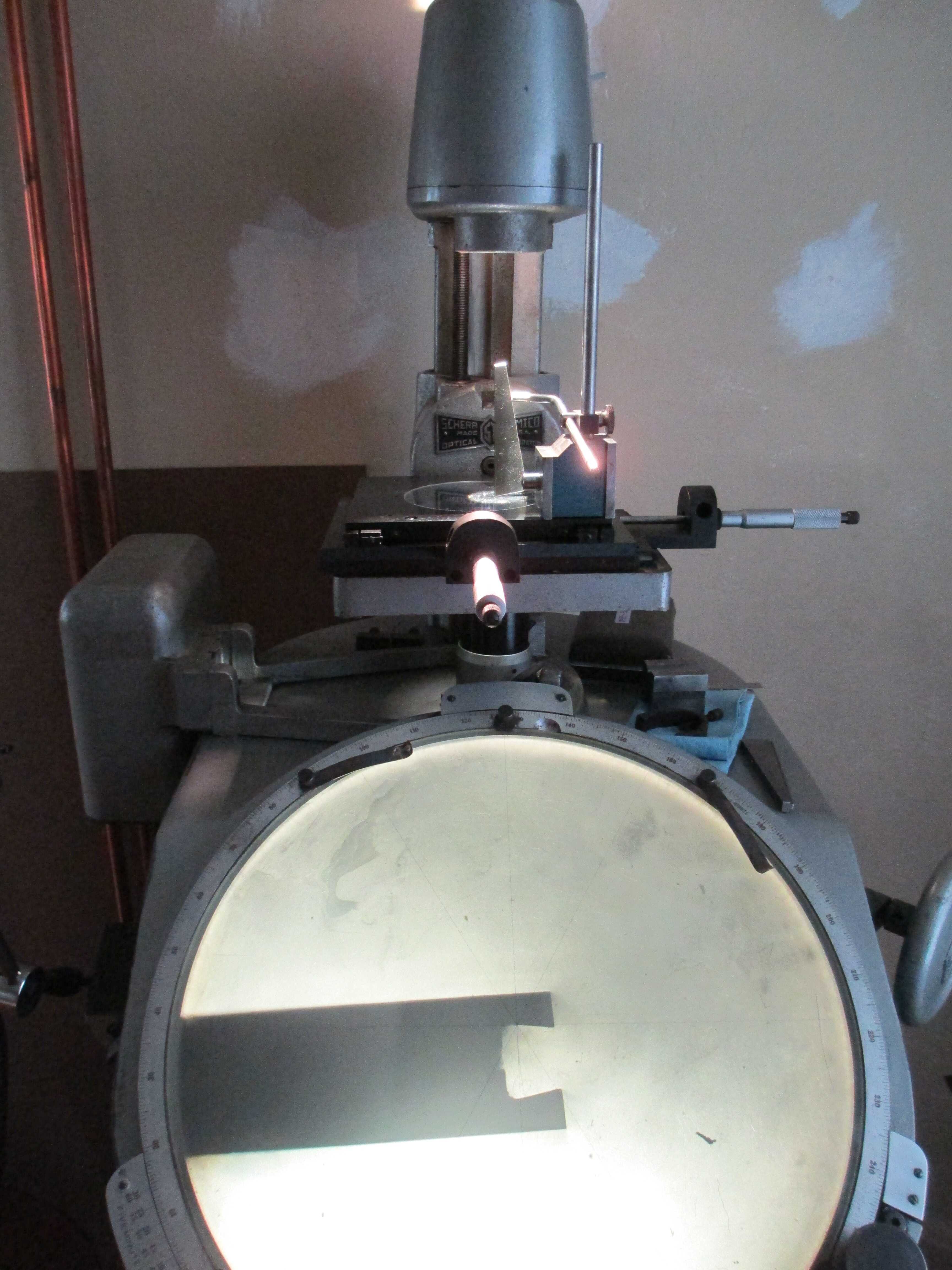
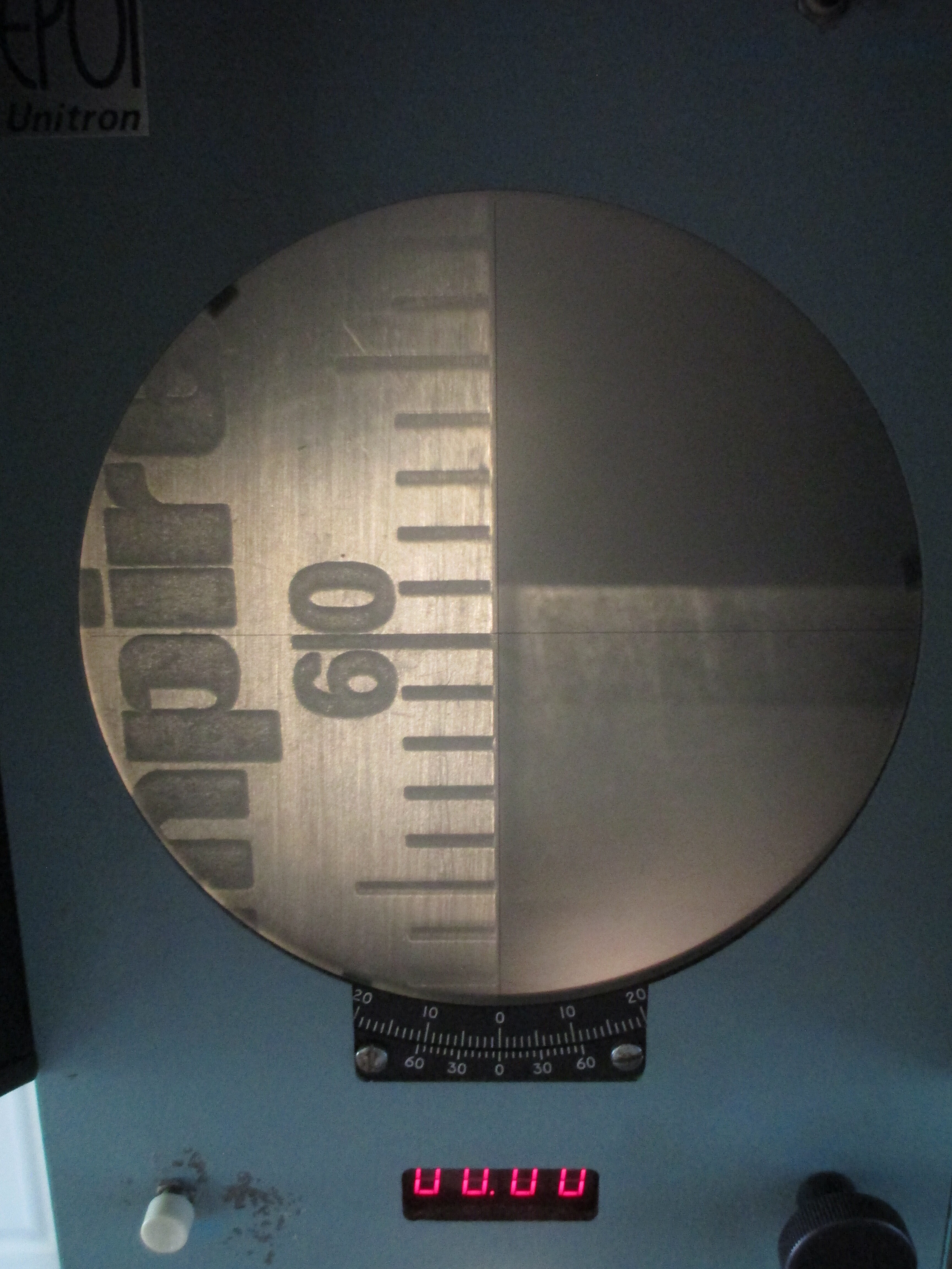
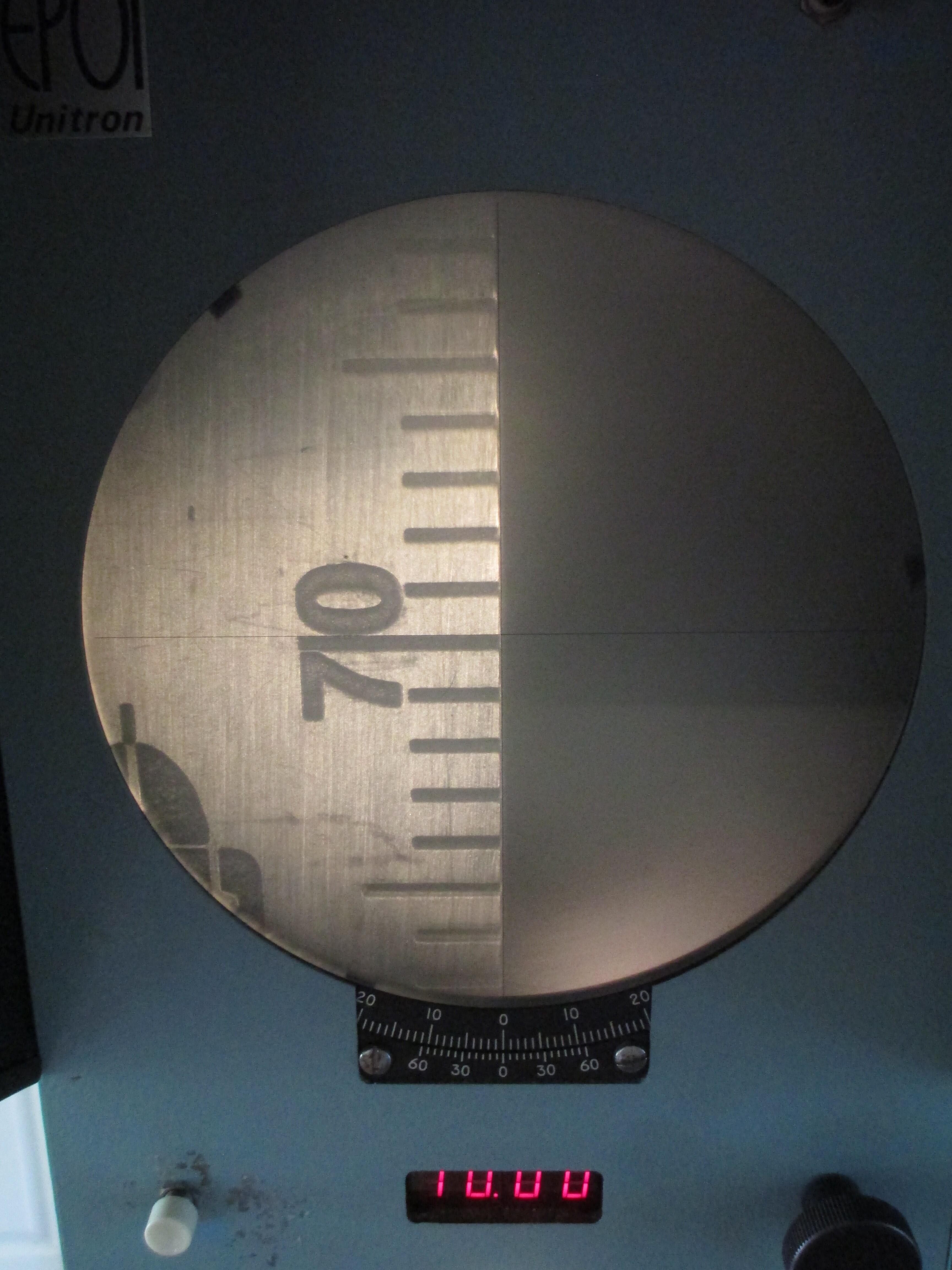
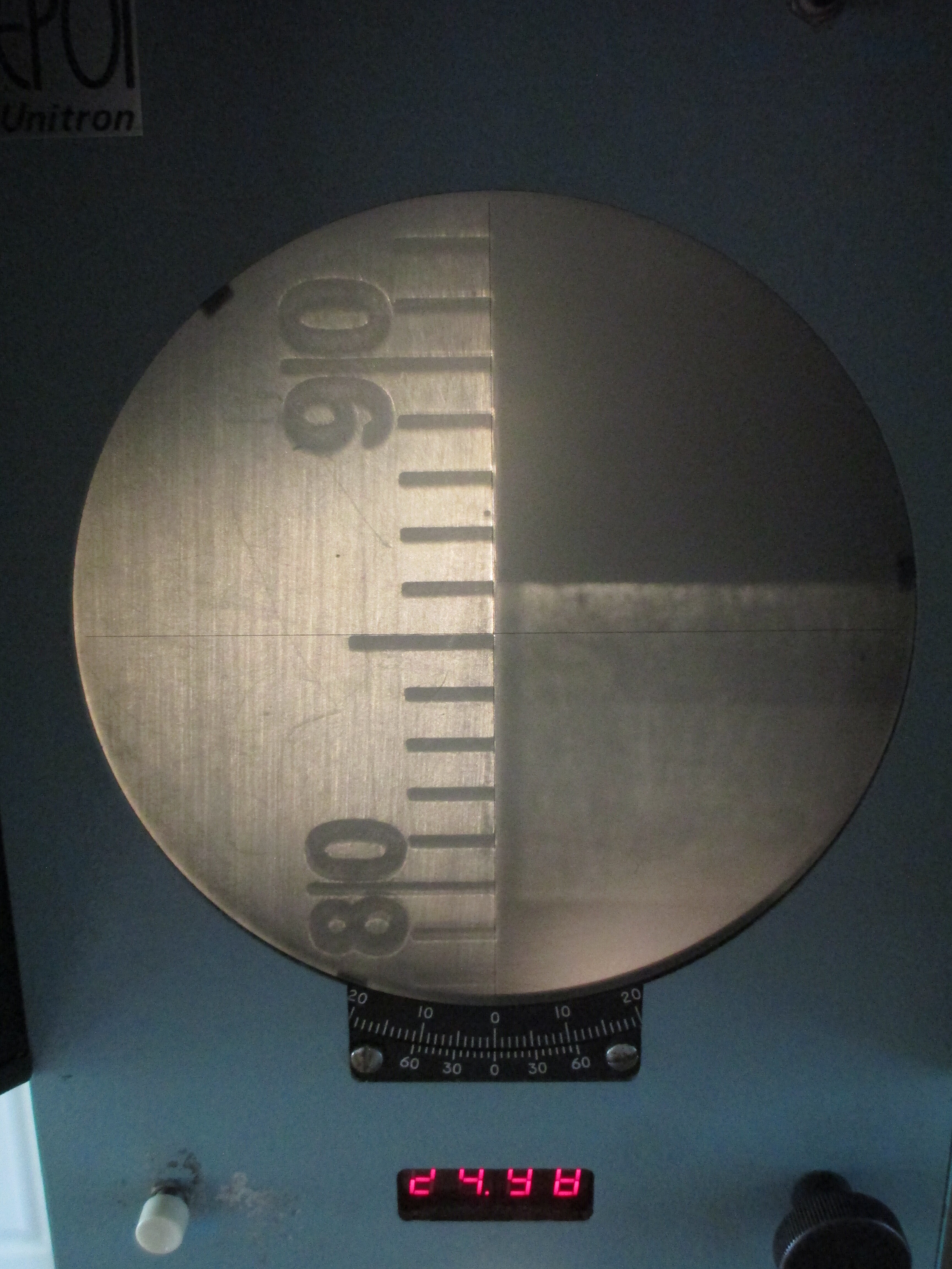
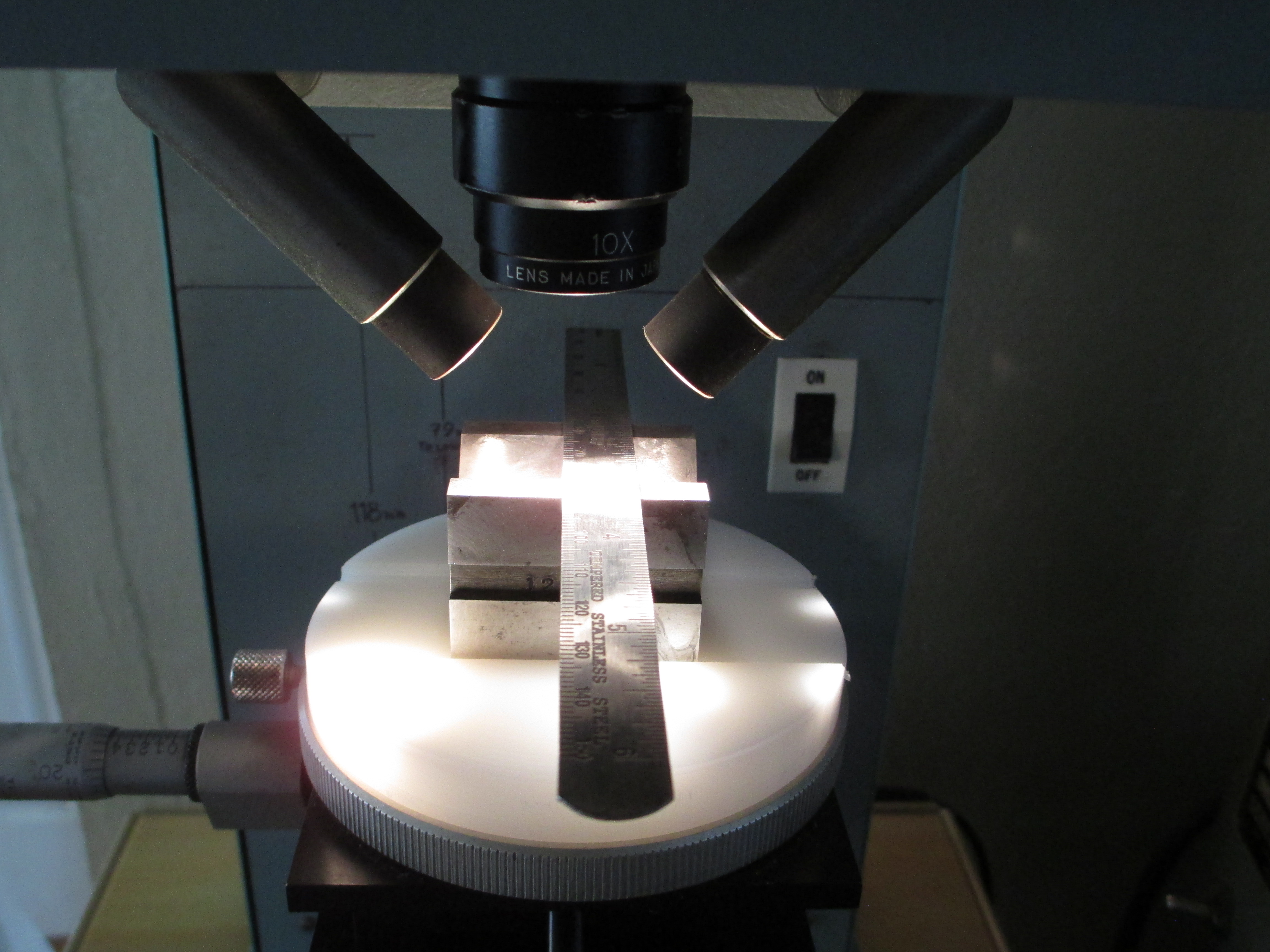
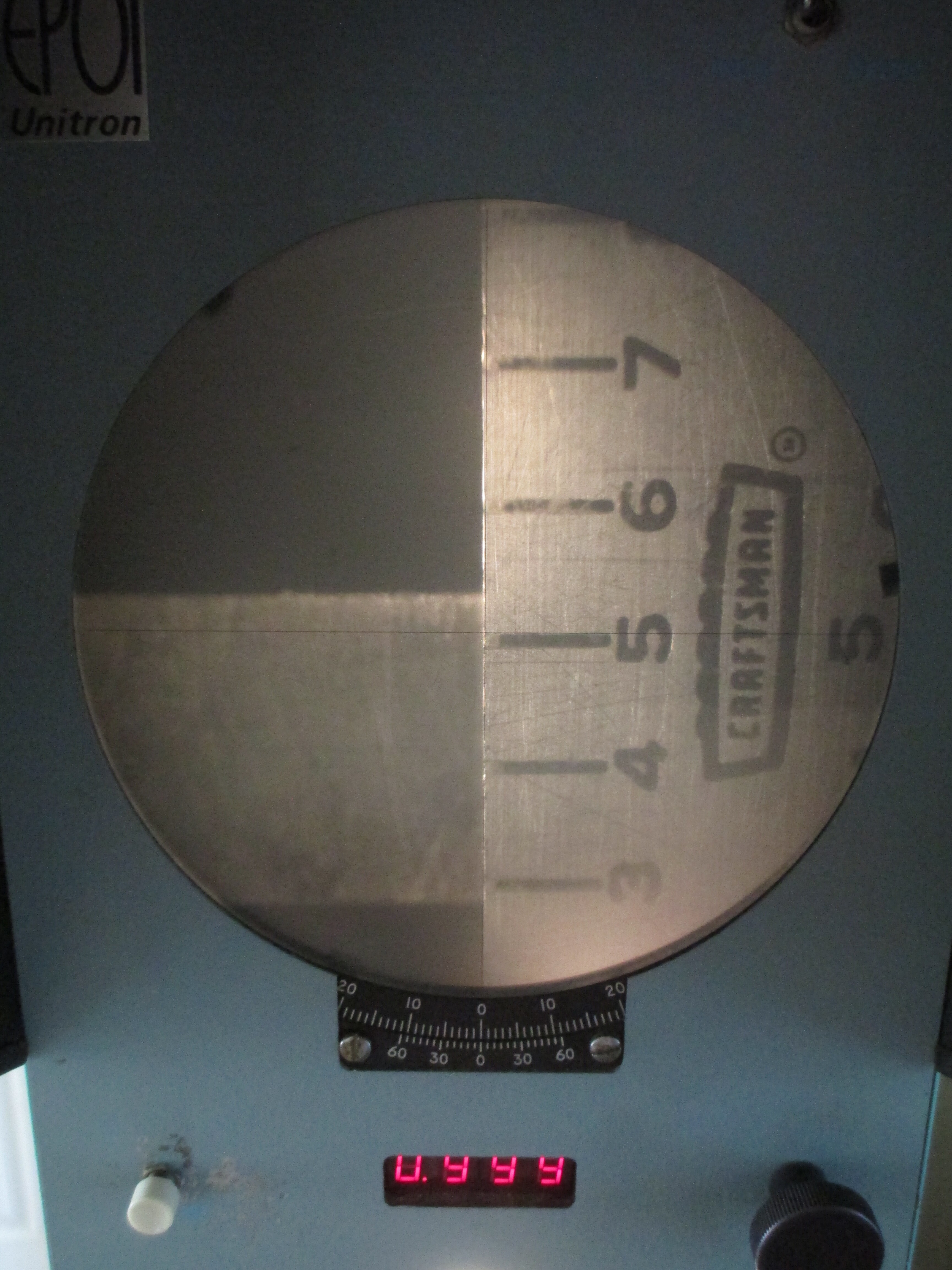
Meet my measuring station. More accurately (pun intended) the comparators. The main sdtation is at the surface plate, in a well lit part of the shop, rather than in an unlit corner of the dining room (the only place where I can a) fit the gear, and b) turn the dark on even on a sunny day)

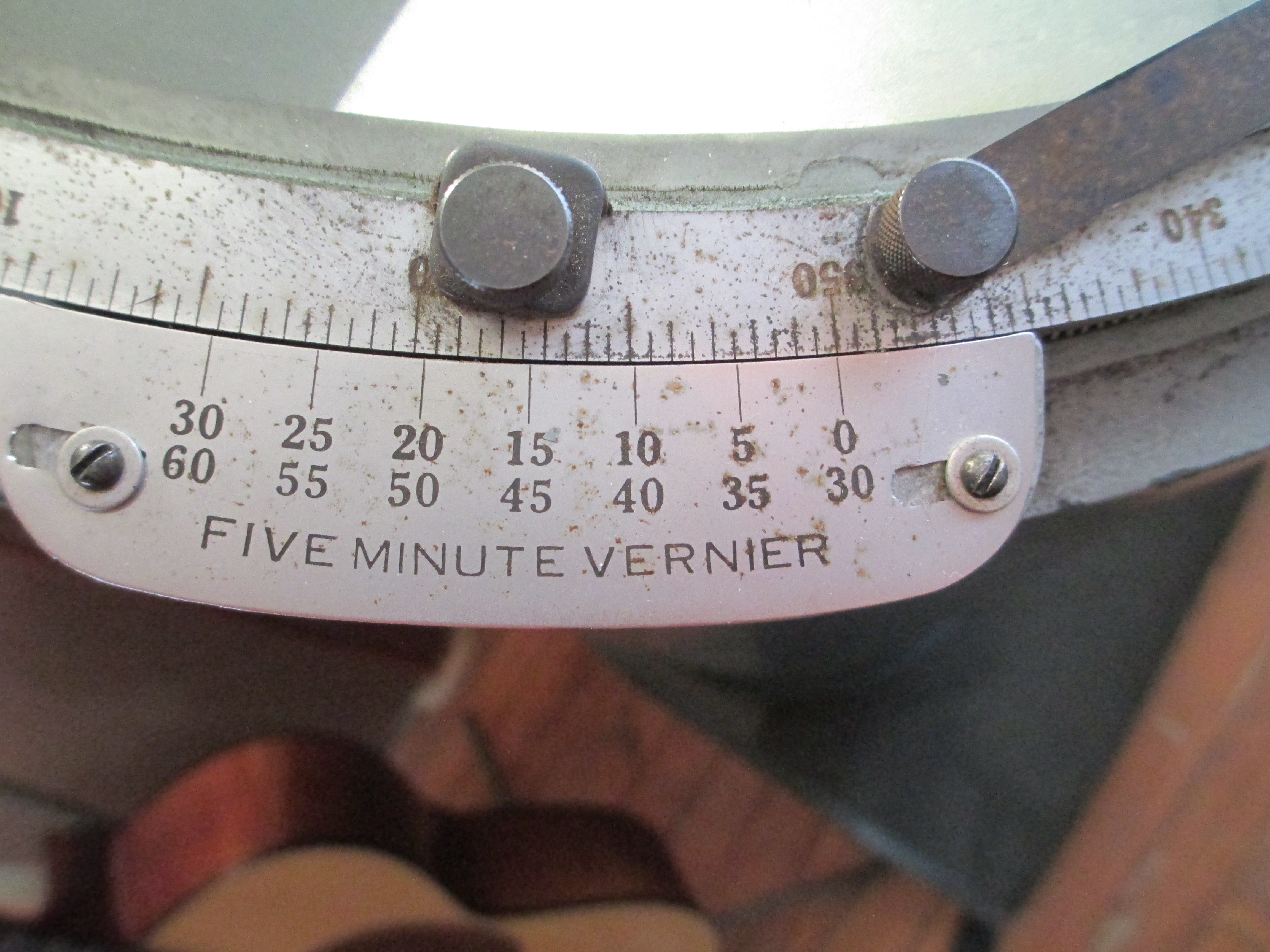
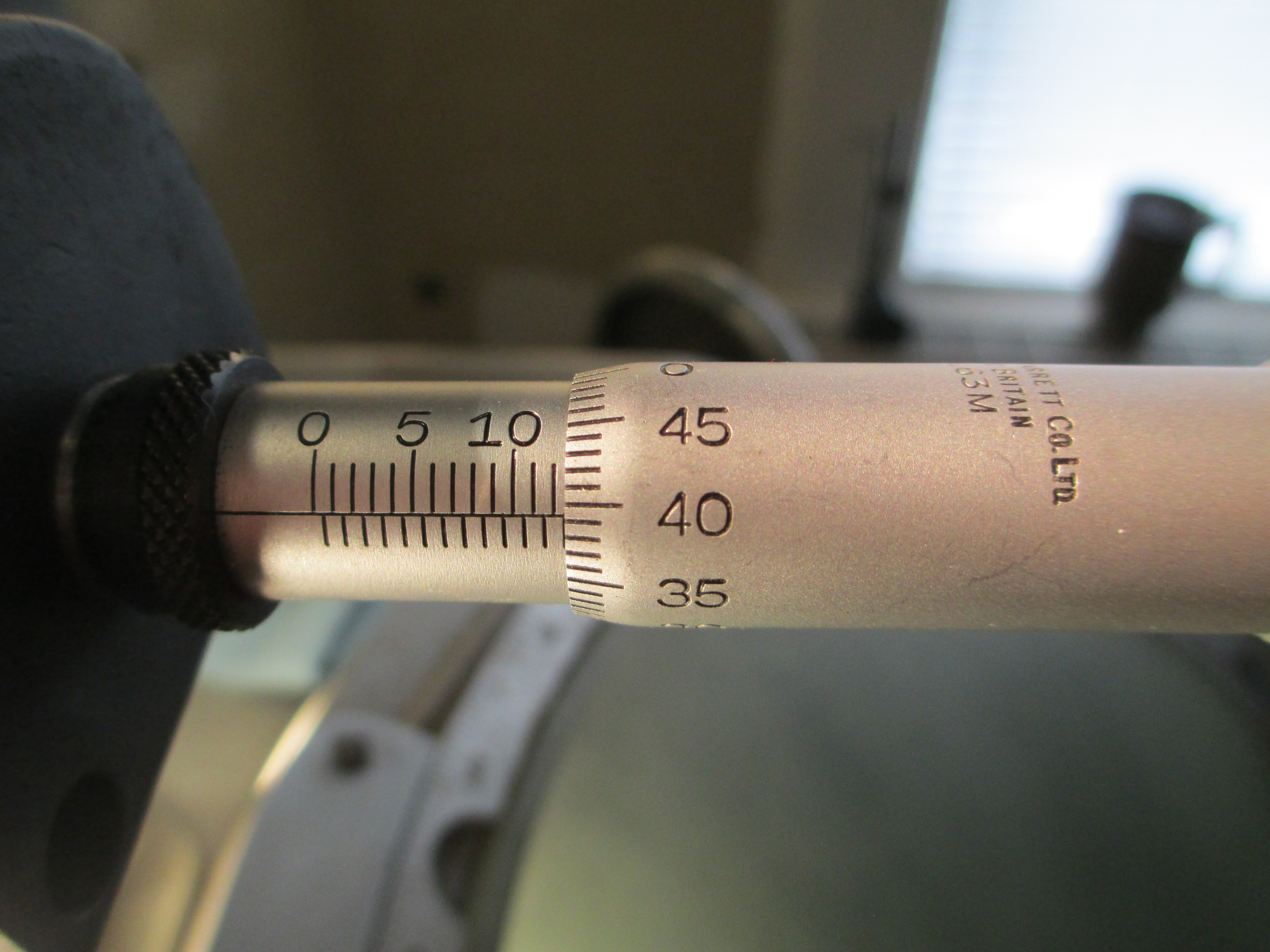
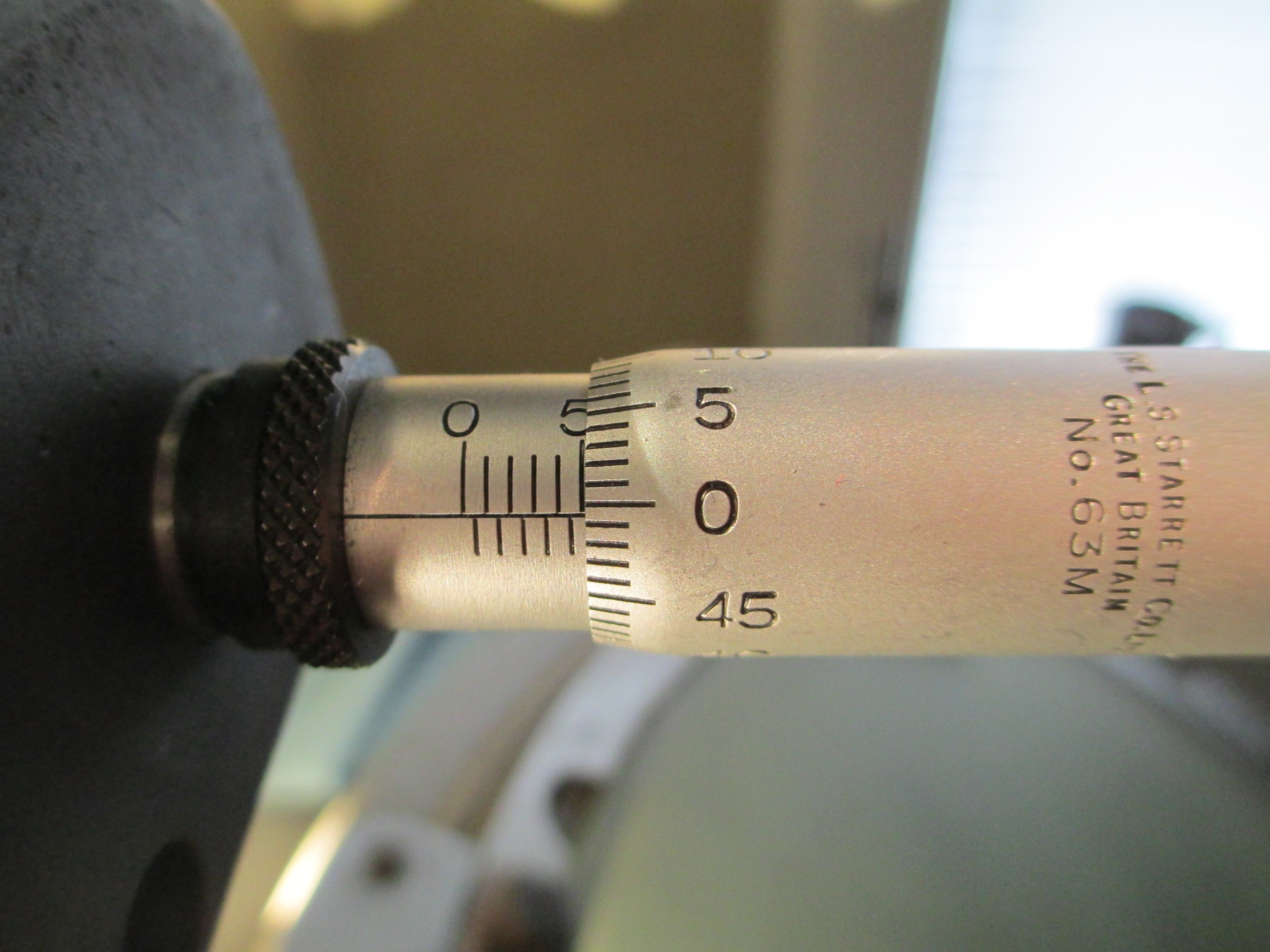
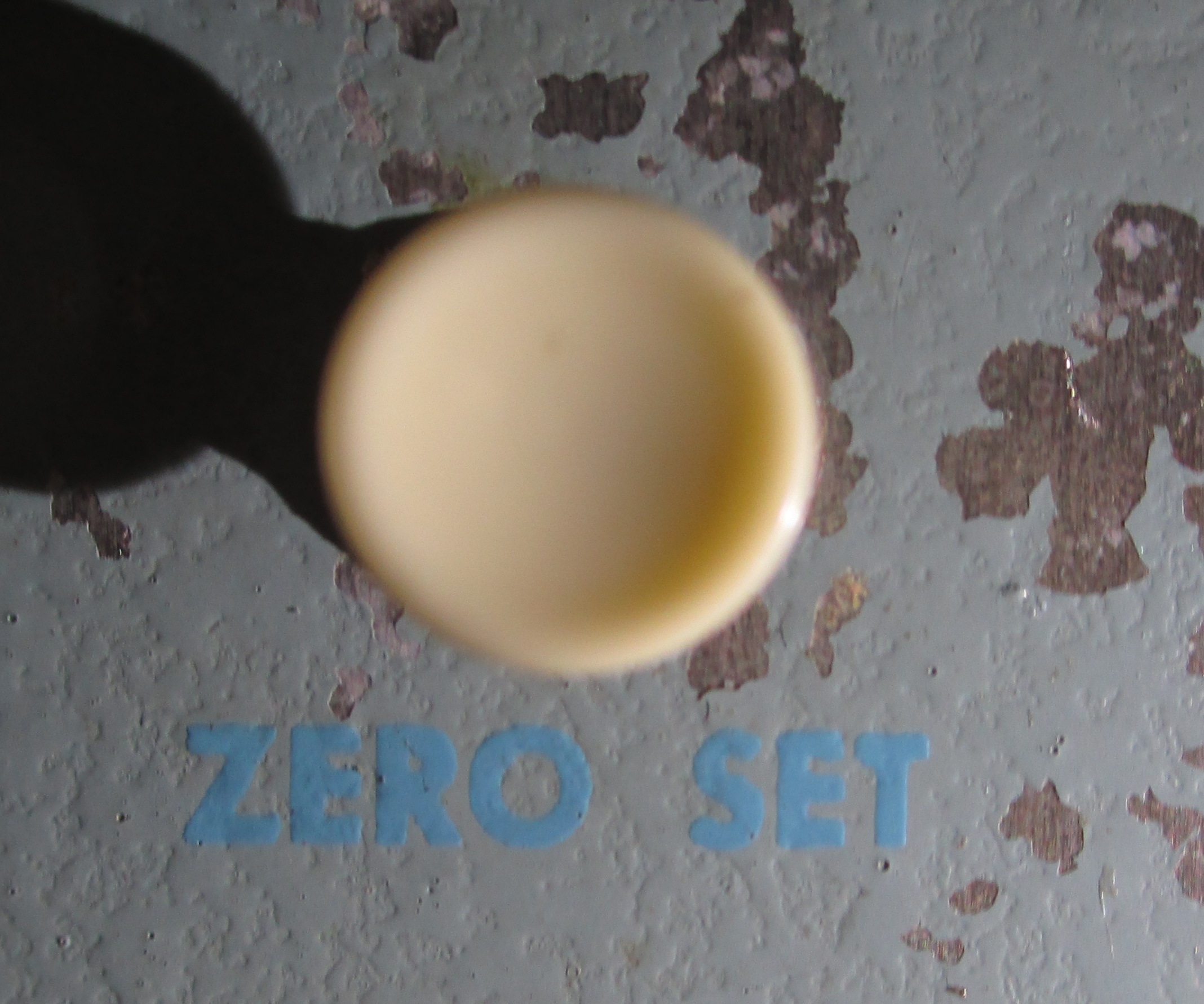
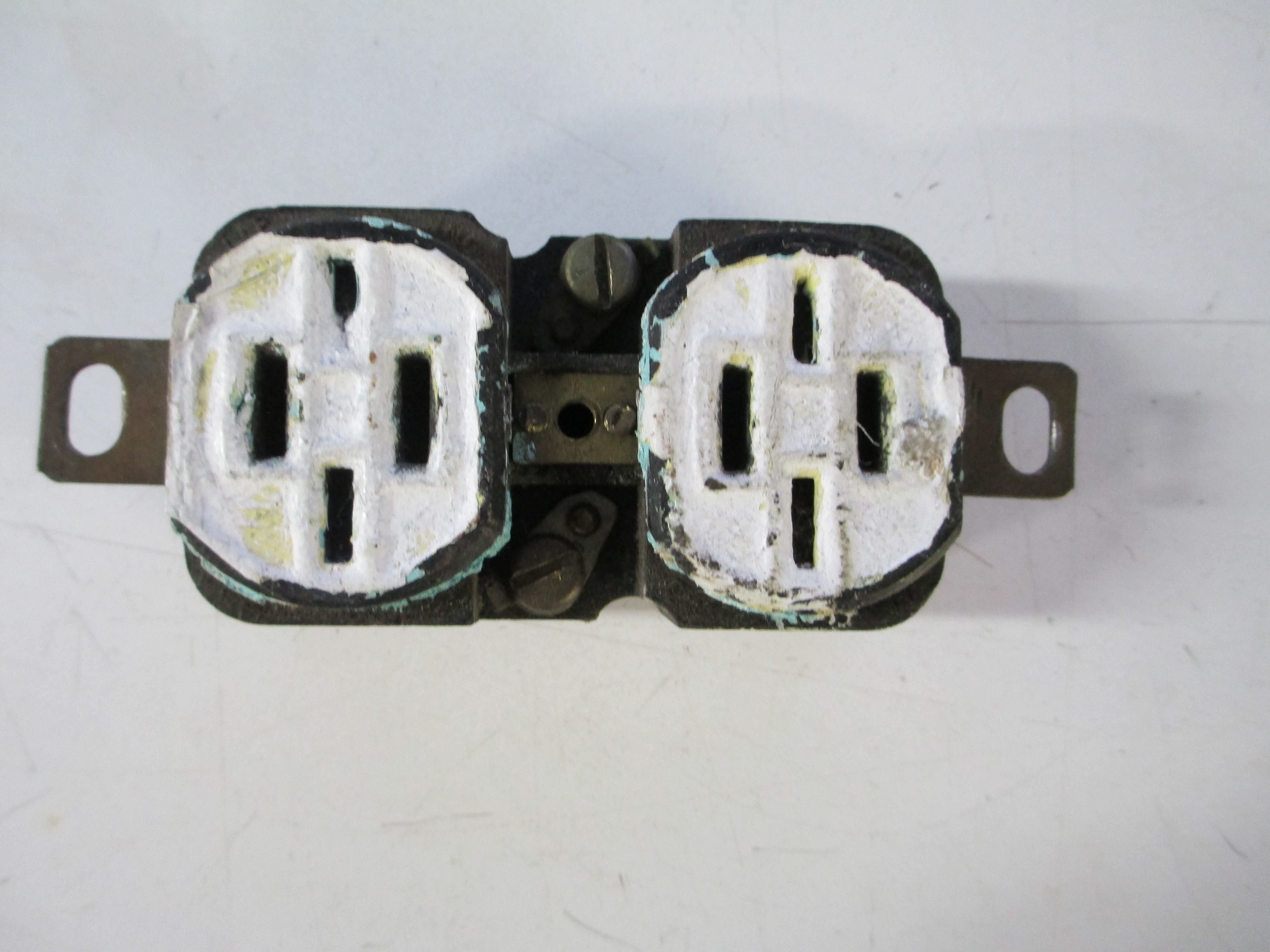
You will note the two optical comparators- a 14 inch S-T (recently upgraded to a lamp that is still made on the telecentric illuminator) and a six inch EPOI projection comparator, also called a measuring projector, or the trademarked “electromike”. The EPOI unit has an interesting history, if anyone is interested, buy II will leave that to the appendix. Key points: they both require 120VAC power. I live in an old house. When I bought it less than ten years ago, the entire house was on two circuits on bare wire knob and tube (not all was originally bare, but by that time it mostly was), and most of the outlets looked like this:

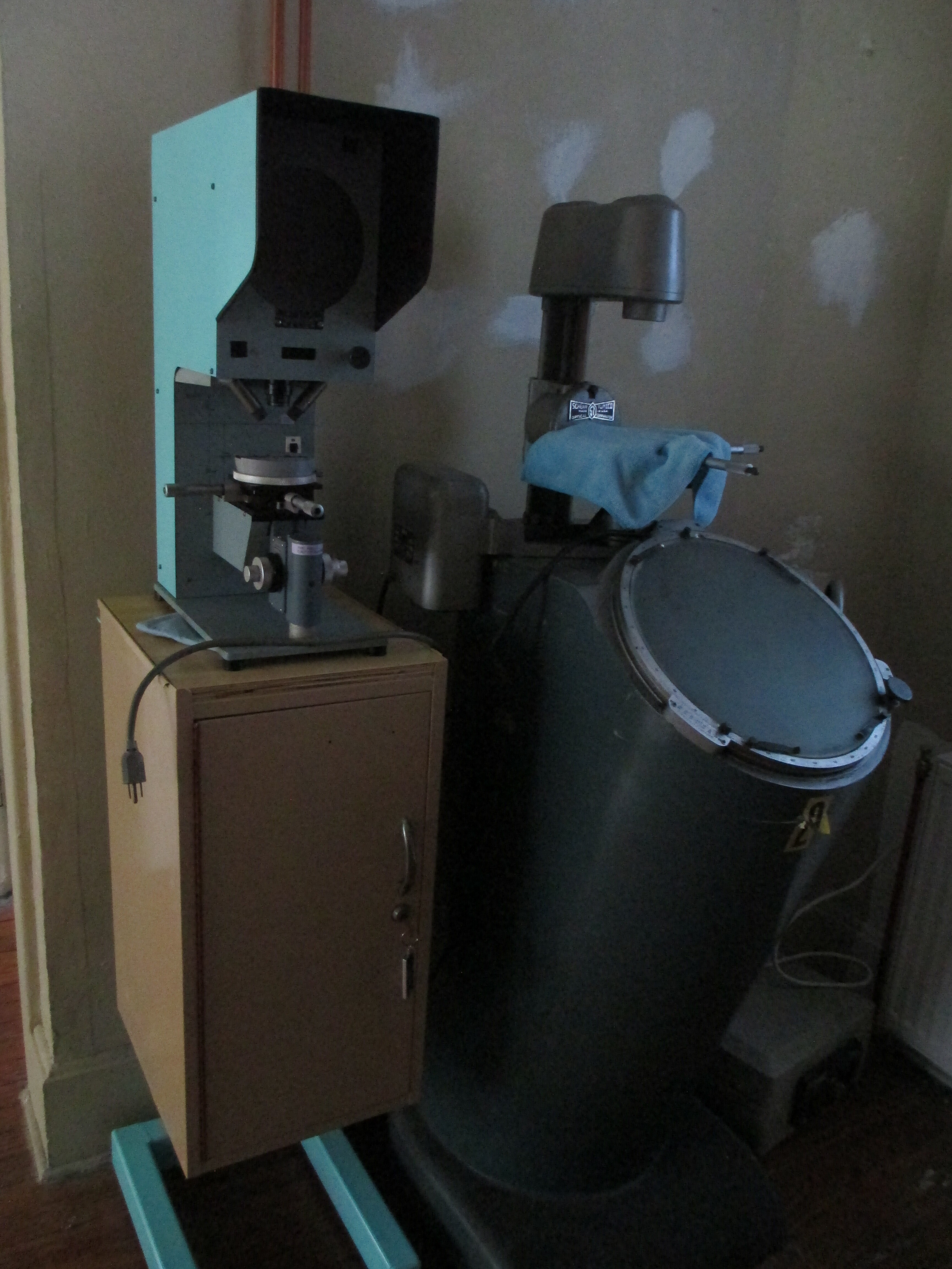
Things have been upgraded as much as practical since- modern wire, grounded outlets, GFCI’s where appropriate, and so on-, but there are still many fewer outlets than needed in some places, and no practical way to expand (60A service, don’t-cha-know). So power strips are a thing. I prefer them mounted securely, but don’t like holes in the walls, so, when possible, I make mounts to attach them neatly to other structure. Lally columns in the basement, or, in this case, the back of the S-T comparator. It is stable (I put a column under the floor to stabilize it), steel, and grounded. Steel means magnets for mounting, so I can put it out of the way easily, but easily get it accessible when I want to.

Unfortunately, the 1950’s chunk of measurement infrastructure has a round back.

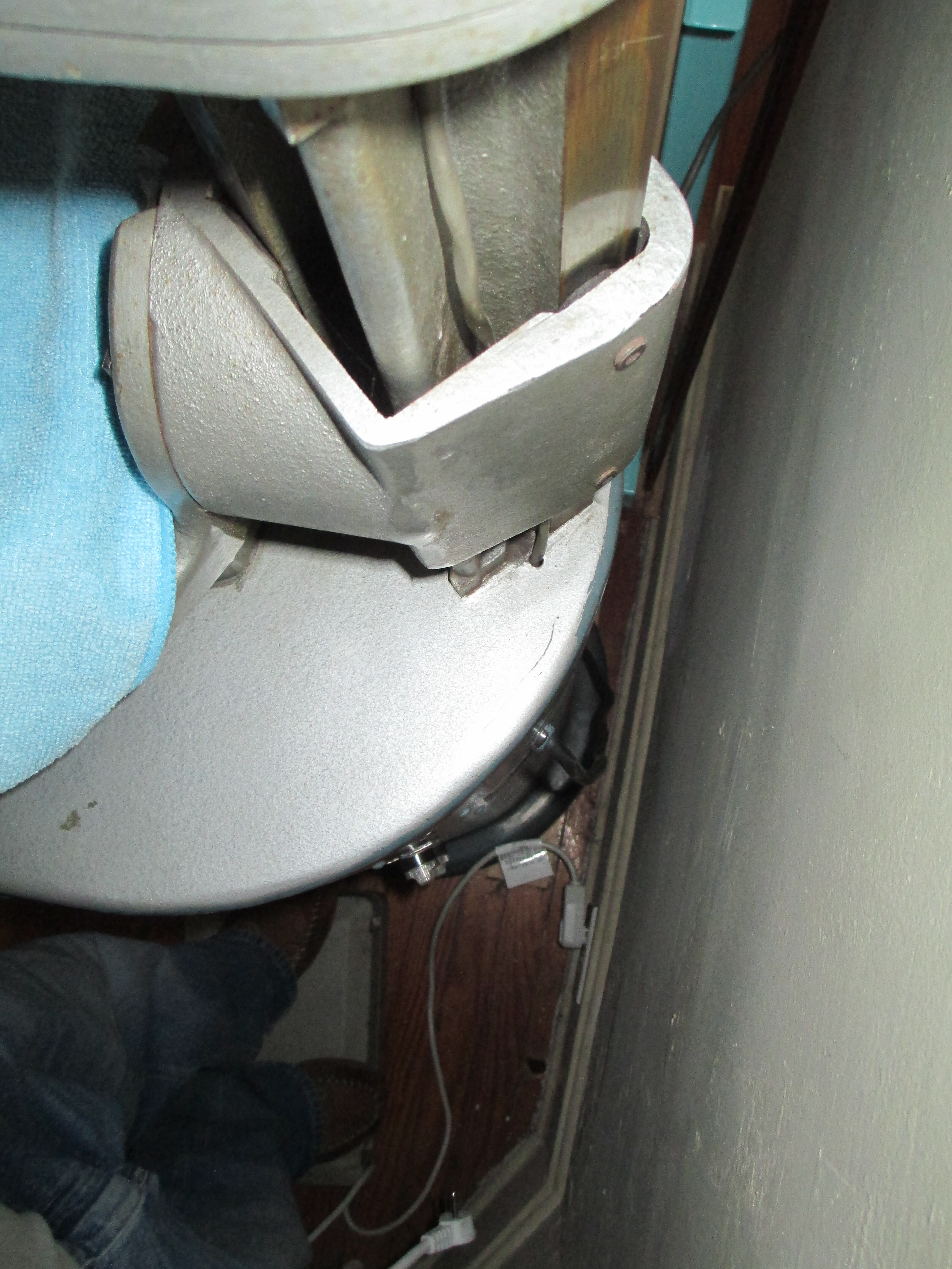
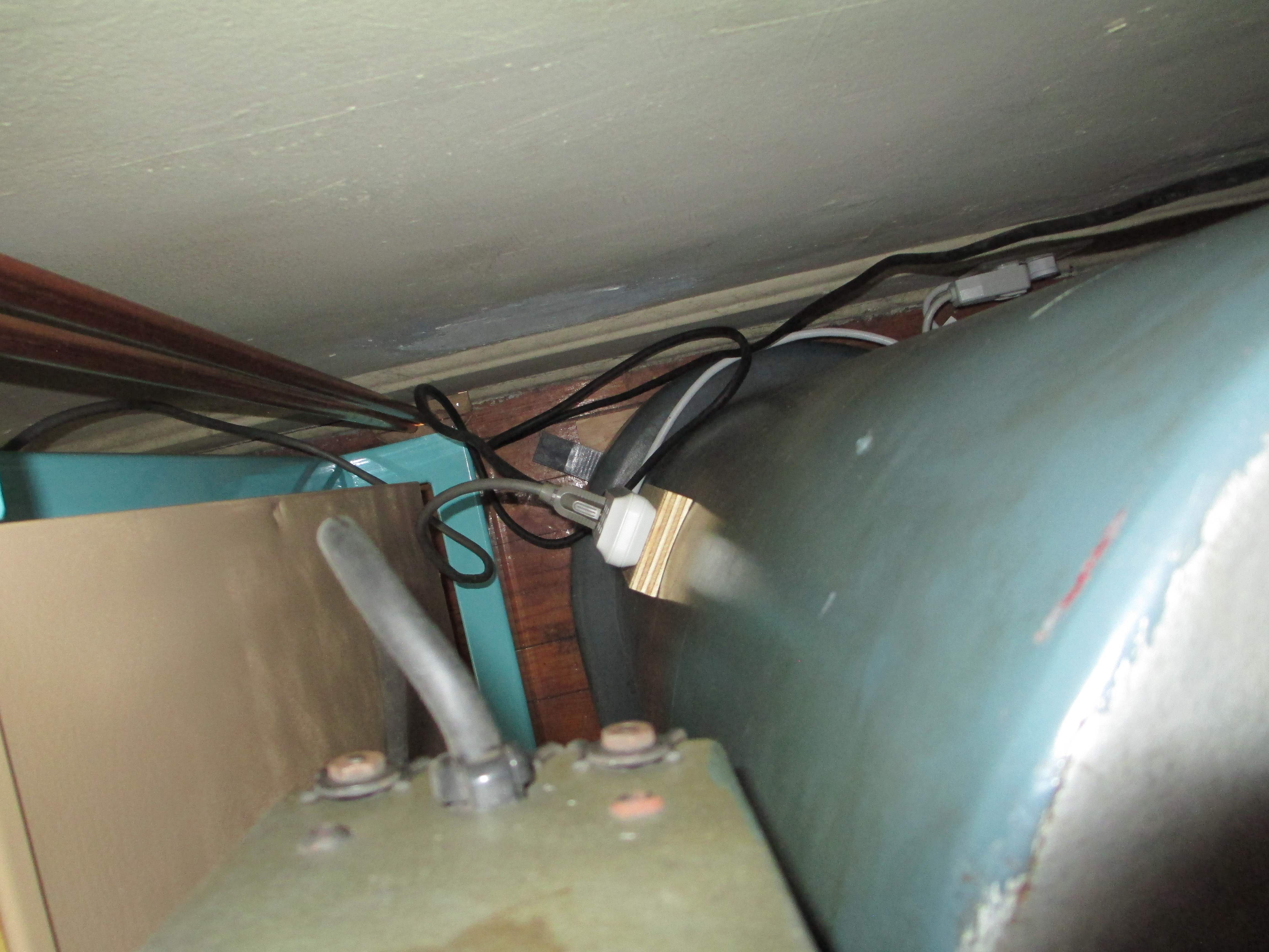
You can also see the one (single, only) duplex outlet available. It is shared with a dehumidifier. The next nearest is either the other side of a doorway or through a floor.

This means a power strip, and this necessitated (in my mind) making a special mount for the power strip. Some people would think “3D printer!”. I think “twelve hours and $10 in plastic for a prototype that may need to be redone. Machine that bugger!” The power strip is 250mm long, so the Nomad is sufficient at 200mm. Magnets are on hand. Lots of magnets. I have screws. Lots of screws. I have epoxy.
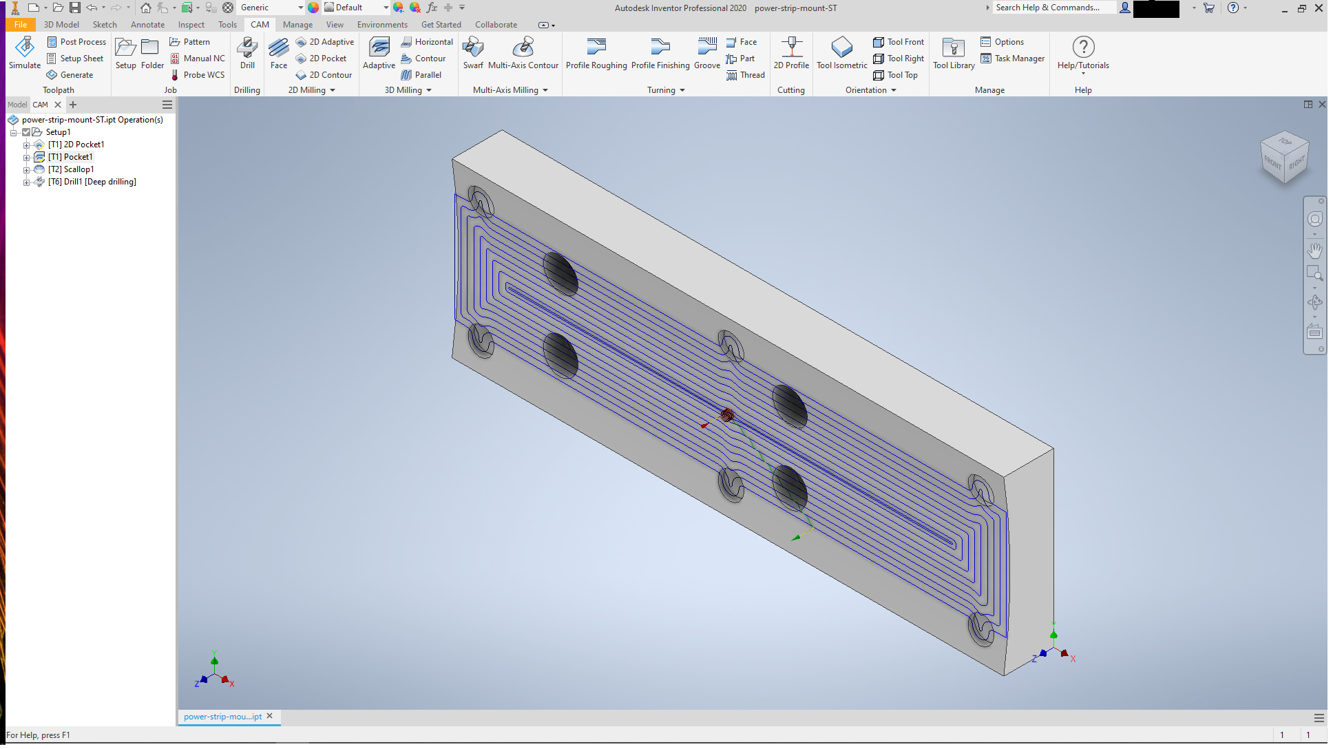
First, the model:

A block of wood:

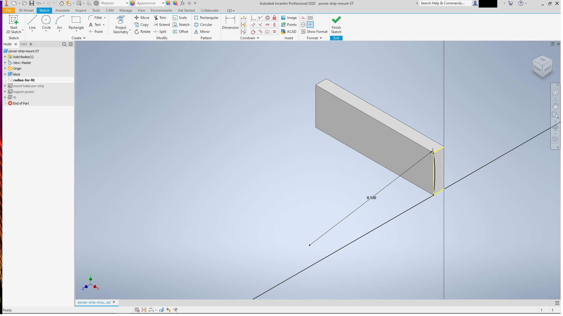
with four holes for the #6 screws to hold the power strip. Counterbores for the washers and nuts

Six magnets should do. Rare earth 10mm dia, 1.5mm thick.

The bores are deeper than the thickness of the magnets, since the last step is fit to the radius of the back of the S-T comparator. Some depth is taken by that. The bore axes for the magnet pockets do not match the normal to the final surface, but are close enough.

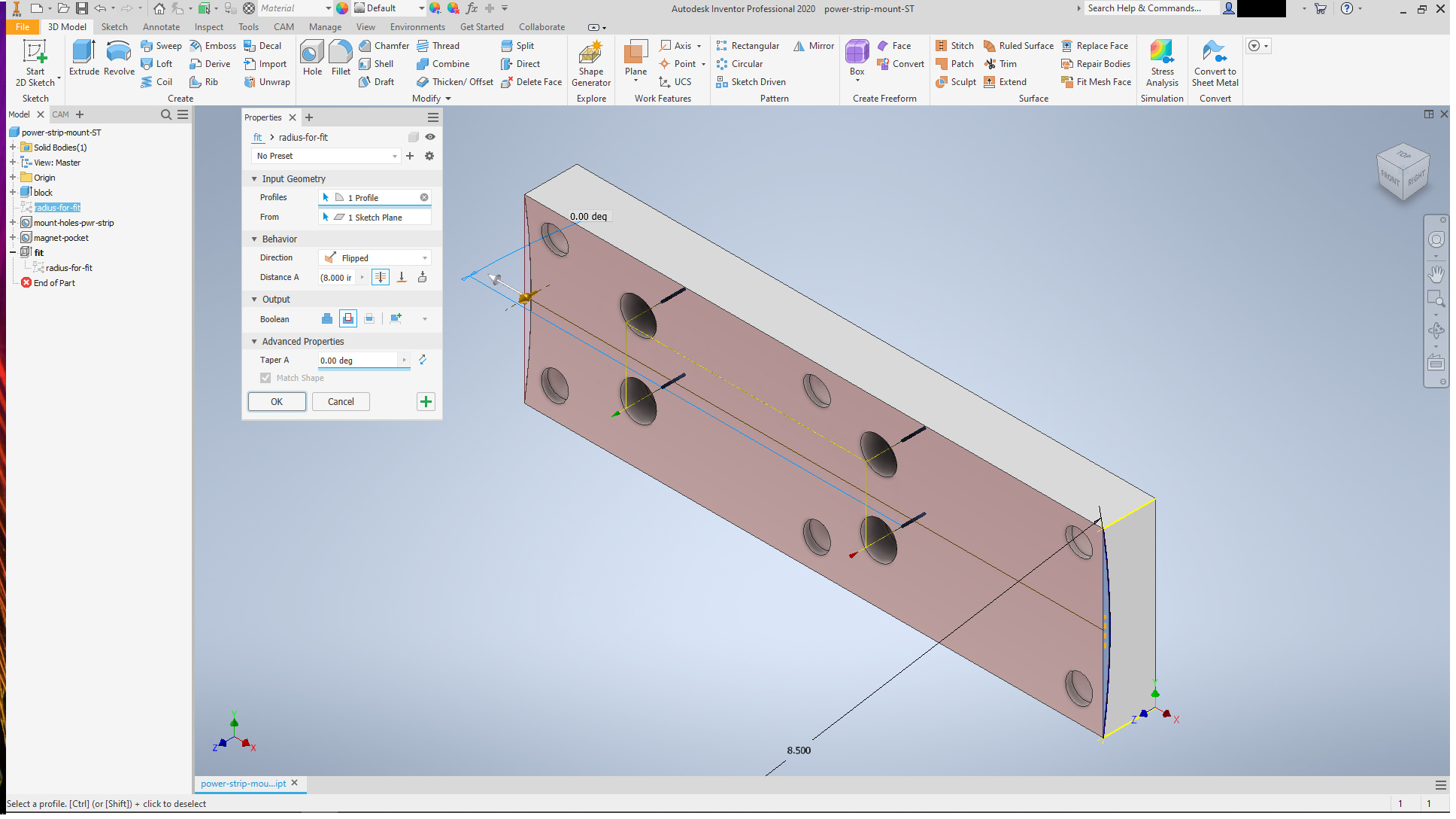
Machining on a 3 axis machine is easy, but due to the pockets for the magnets not matching the surface, assembly took a couple extra minutes.

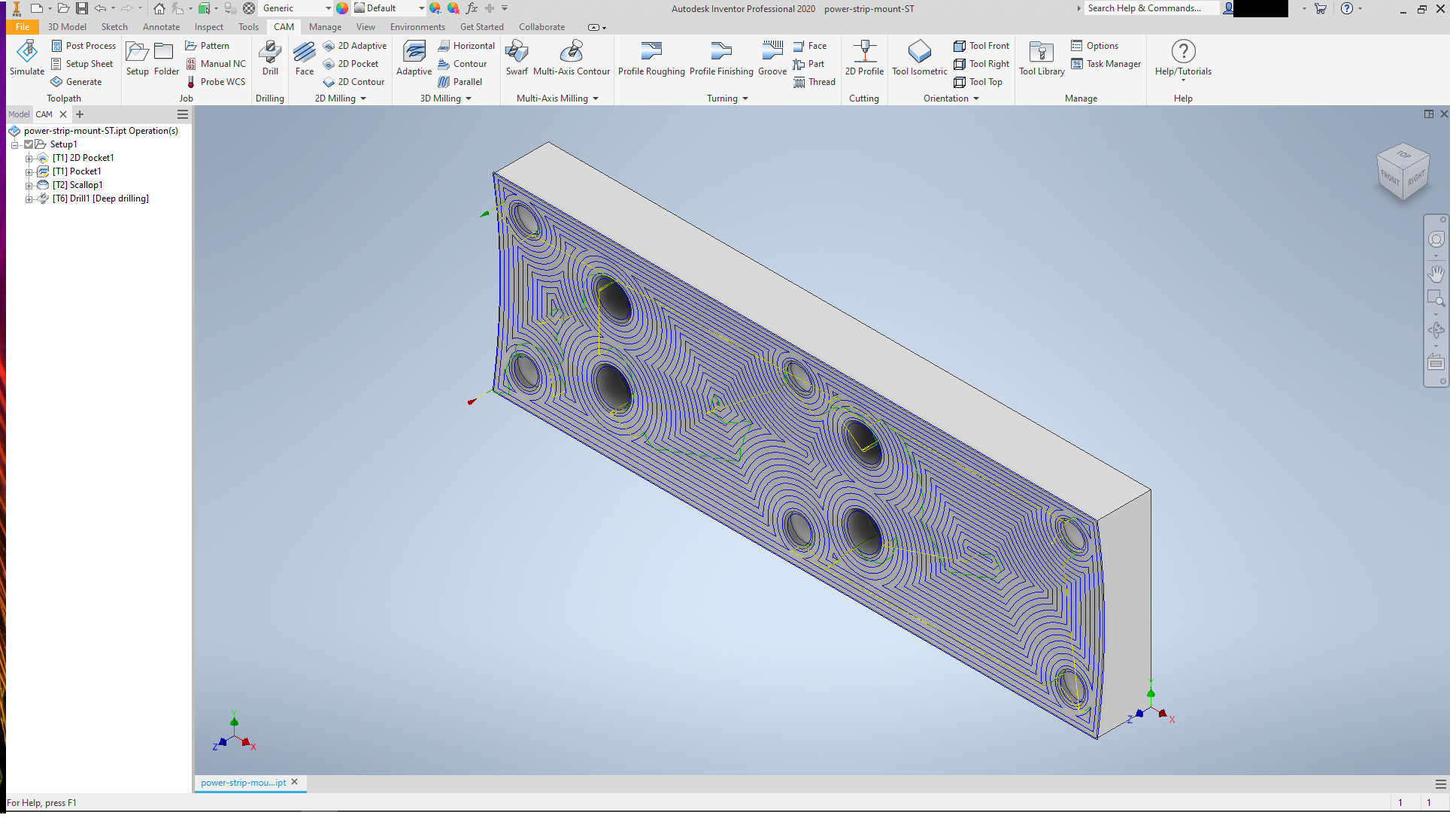
Machining was done using three tools: A square end bit for most of the work:

including the roughing of the contour to fit the comparator, followed by a 3.175mm ball end for the final contour (I chose the strategy for ease, but it looks cool, no?)

and pilot drilling the screw holes

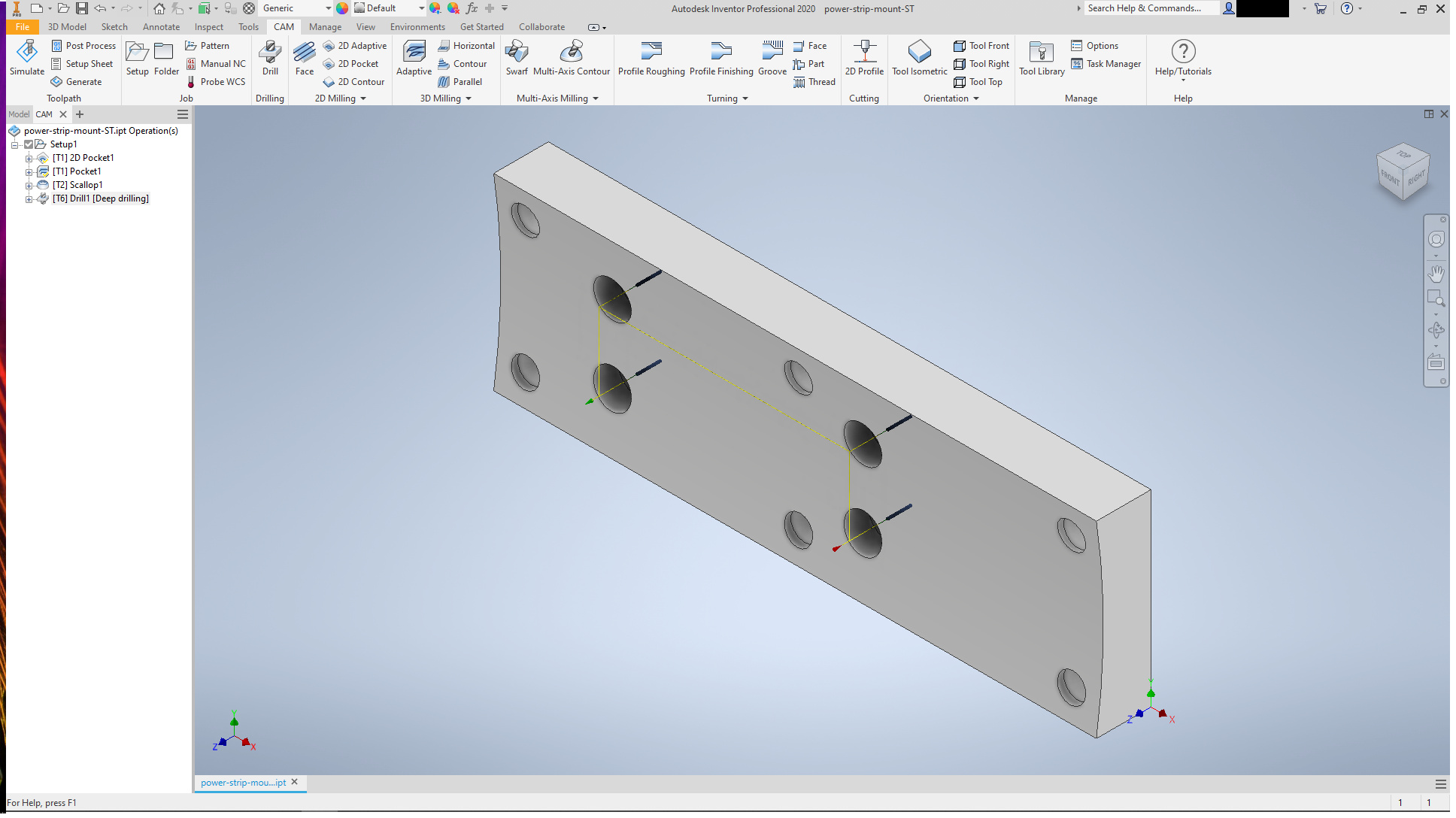
The final drilling diameter (3.7mm clearance holes) is a bit large to drill with the Nomad, and a bit small, at this depth, to pocket using a 2.3mm mill. So I used the drill press to finish them.

To do the machining, I pocketed the well used waste board (it is almost a month old. I am nearly down to the mounting screws at the front, and will need to be more careful for large parts soon)
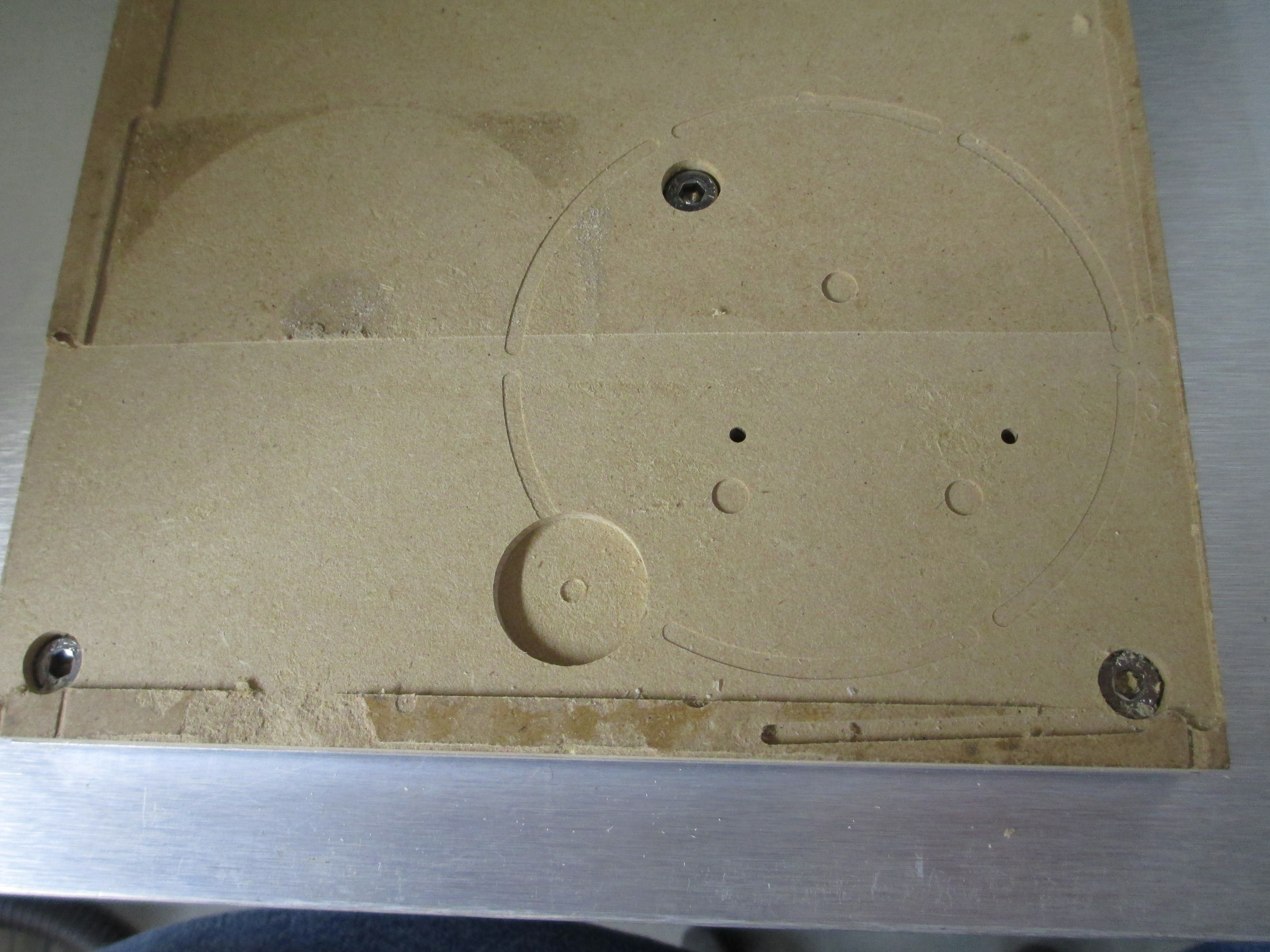
using this model

The position left about 1mm on the right, and a good lip at the front, for positioning. The zero for the part and for the pocket were front right bottom so I zeroed once (setting the depth of the pocket by setting the Z in CM), and ran the pocket and the part.

I have no photos of running the part. It only took about 15 minutes, fixture pocket to finished part, so here it is after epoxying the magnets in (this is why I couldn’t use the plastics I have on hand):

The magnets are epoxied in flush to the surface, the screws, washers, and nuts ready for the power strip.

Mounted and test fit:

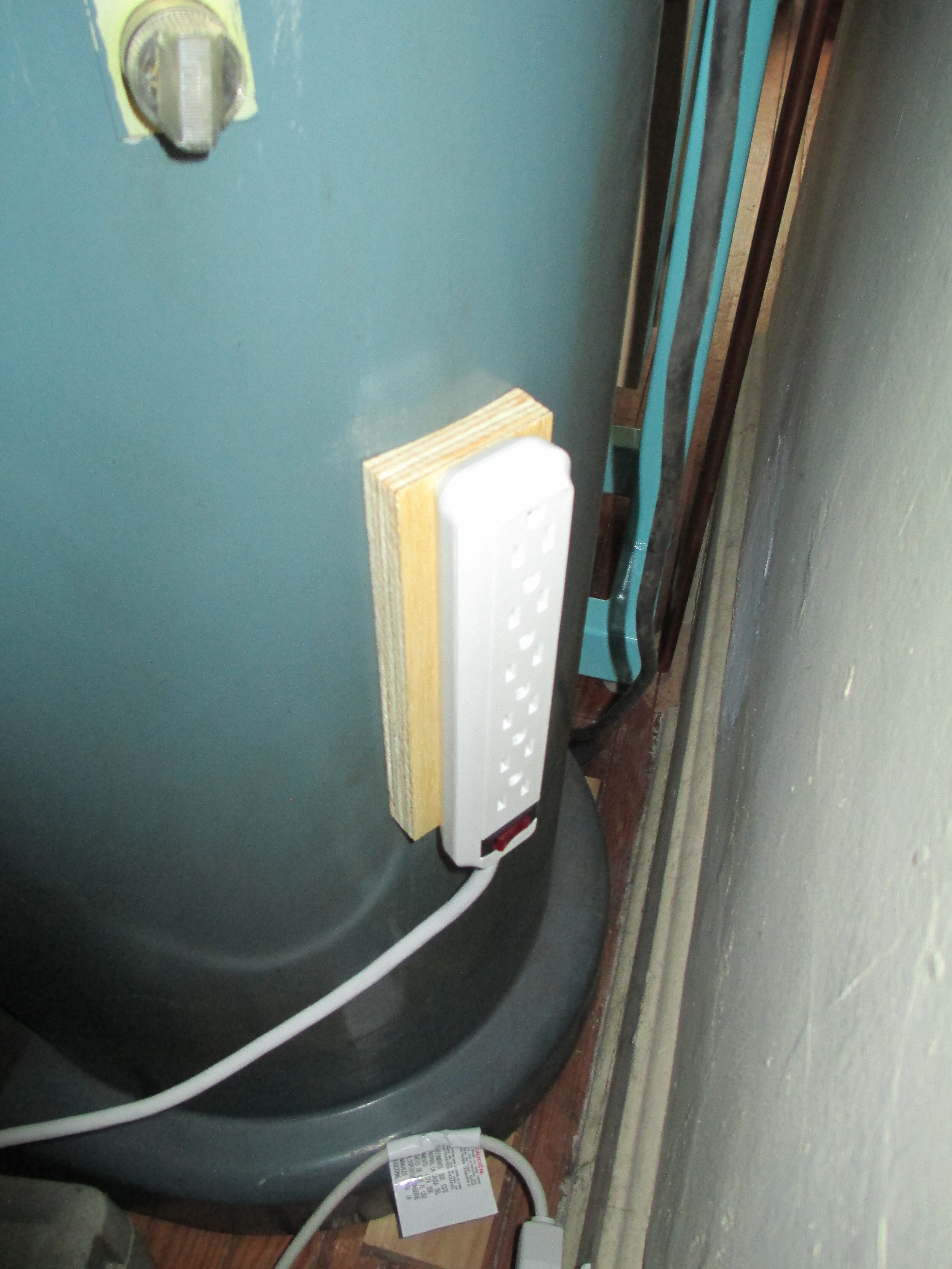
and in final location:

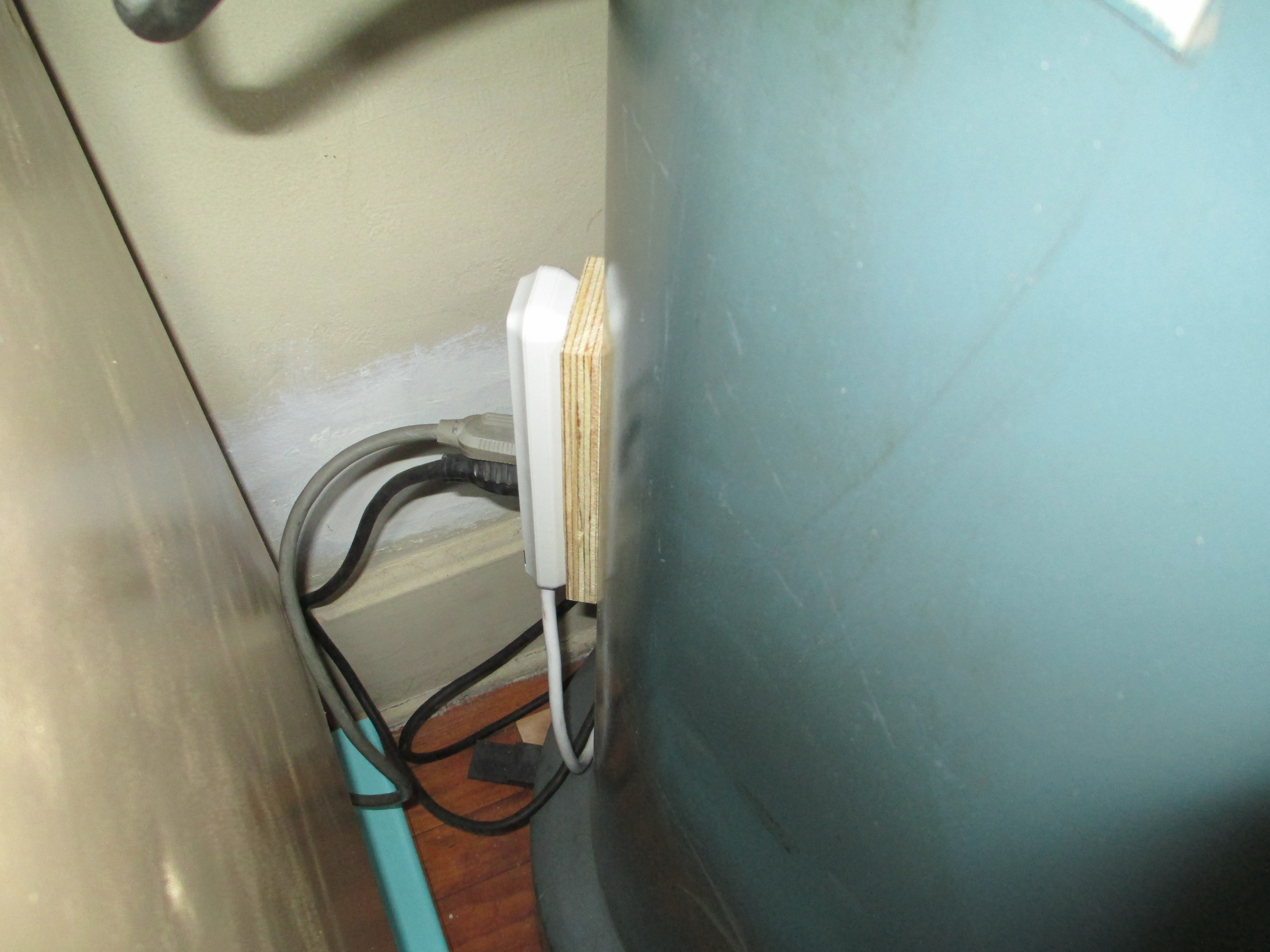
The fit is snug, with no rock. It took one jiggle of the top to get a good seat.

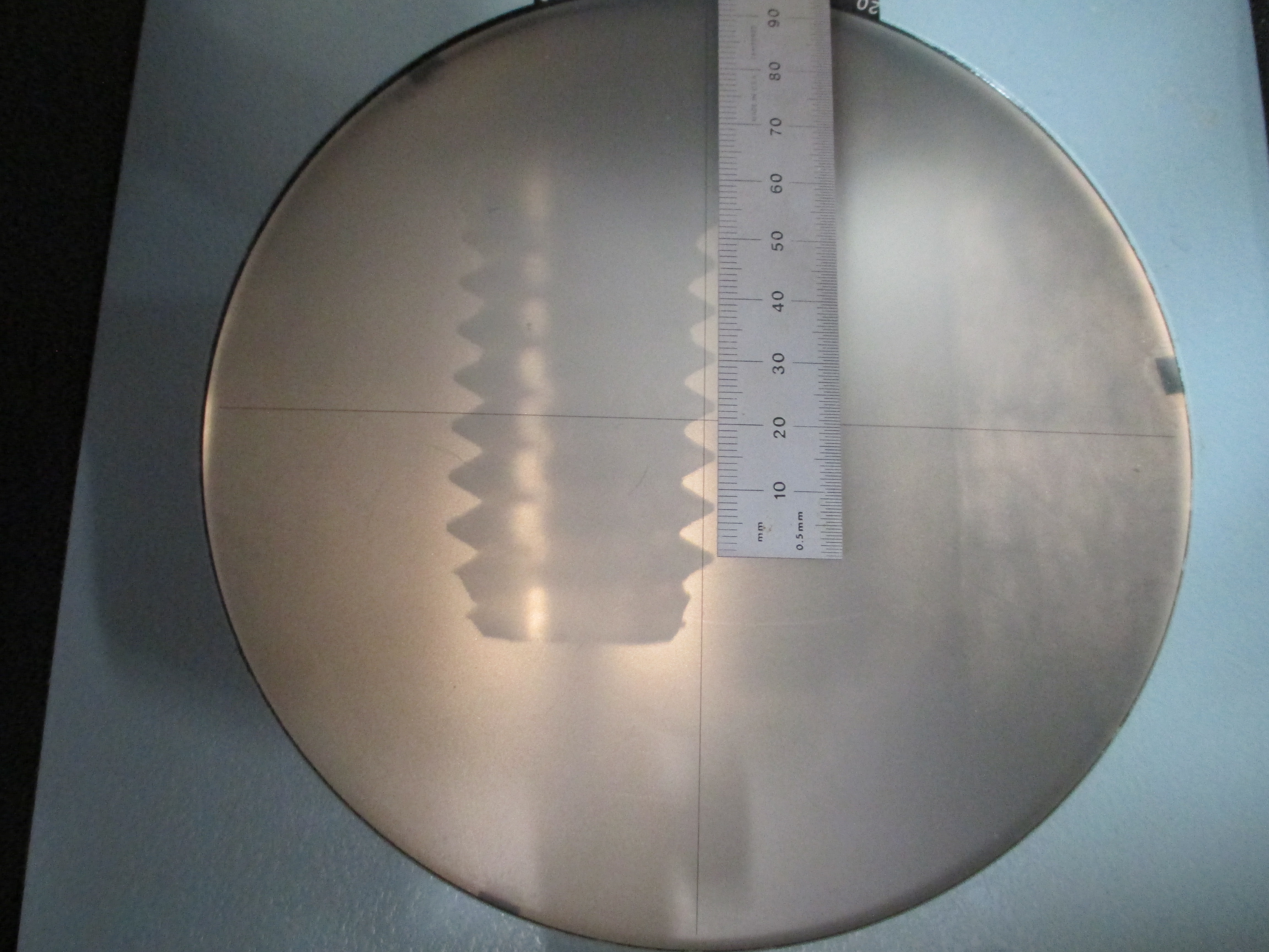
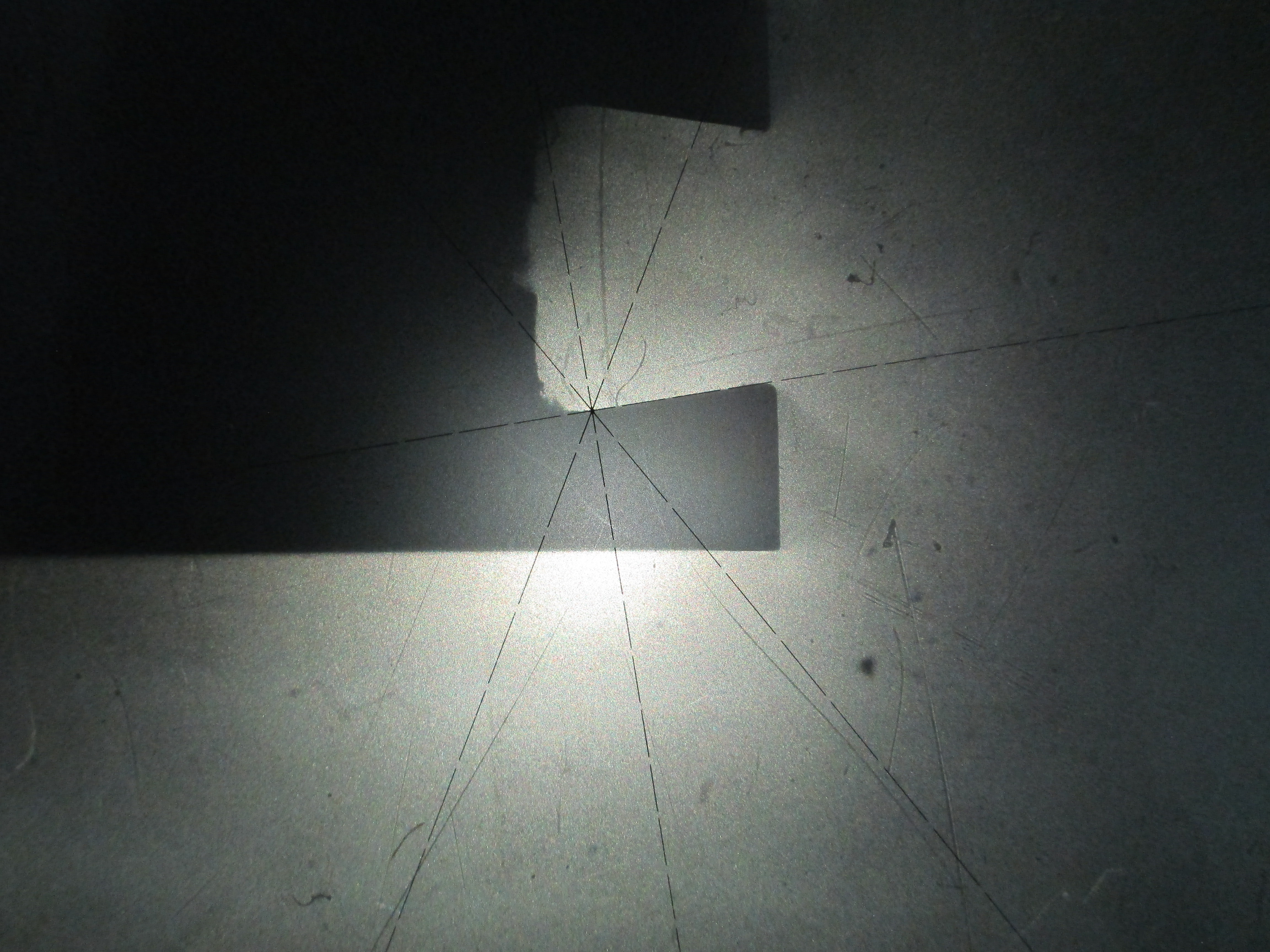
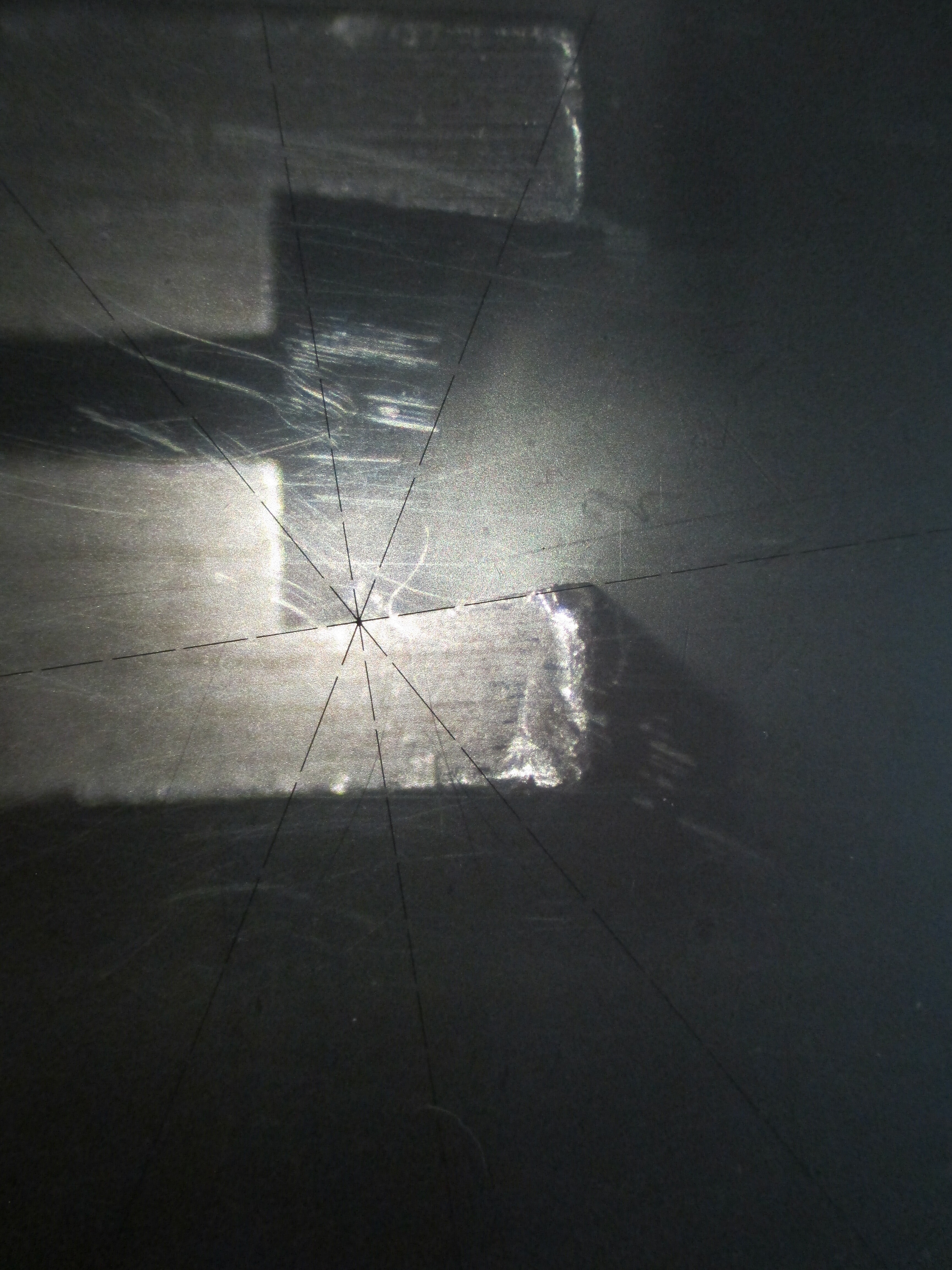
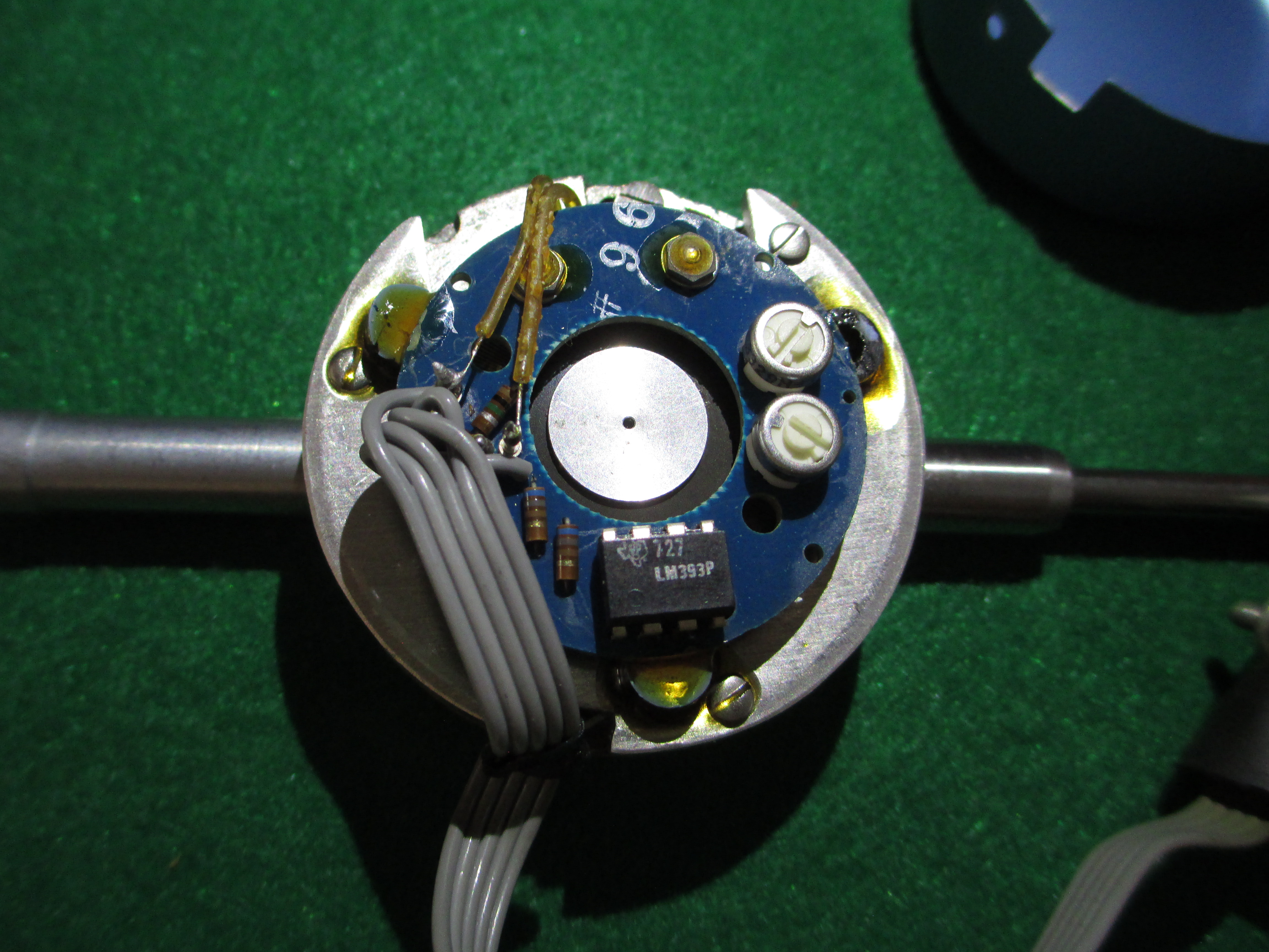
Now the interesting part of the EPOI unit:

I bought it on ebay to restore and use. It is third (fourth? fifth?) hand. It is portble enough to use when teaching. I knew it would take a bit of work from the photos in the listing. You can see that I have done a fair bit already, the most visible thing being that most has been repainted (and the sheet metal has been marked out with dimensions for locating specimens on the sheet metal behind the stage. This also helps with making accessories for holding specimens. That is foreshadowing, hopefully about one days worth, if no emergencies pop up).

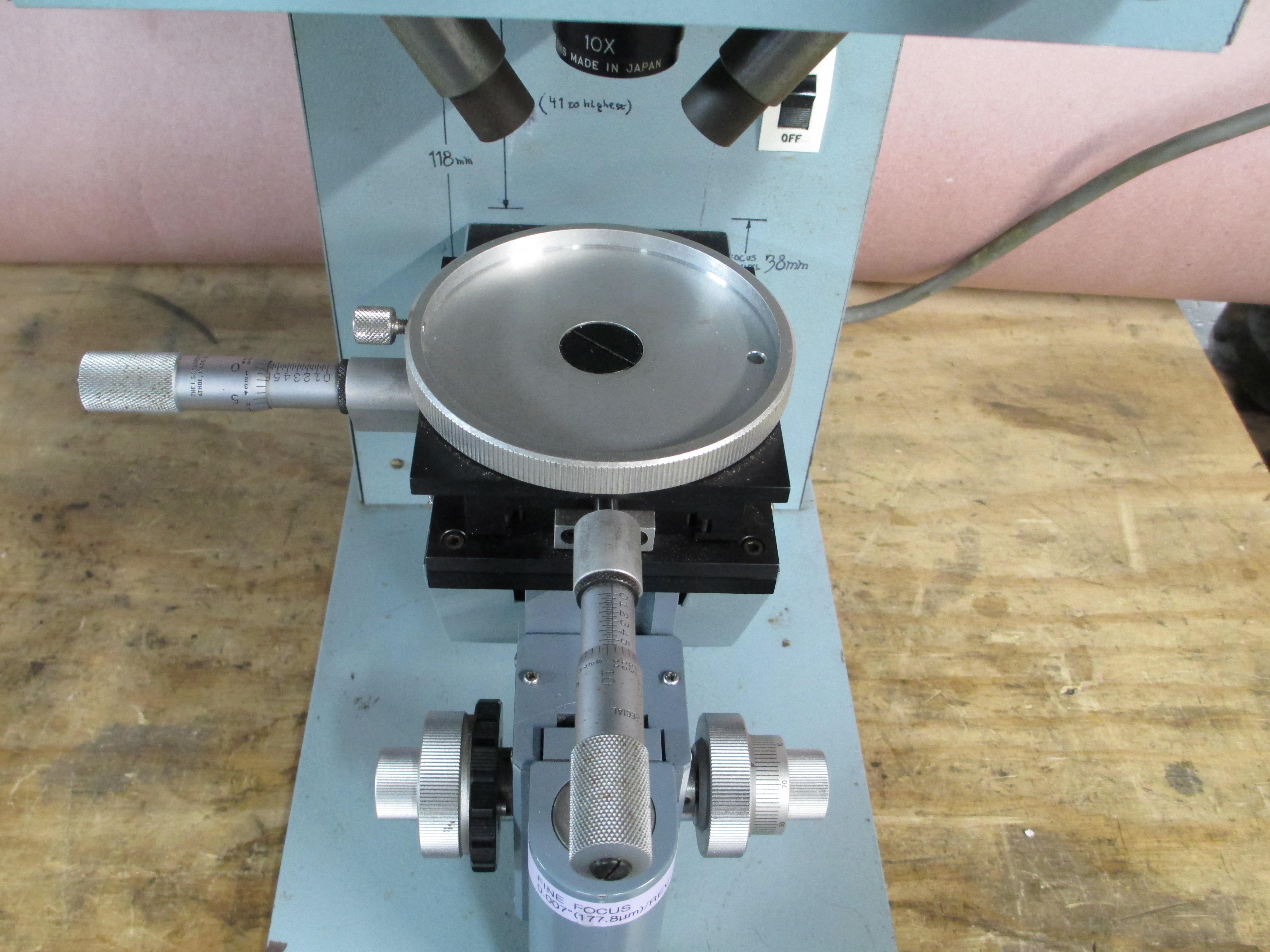
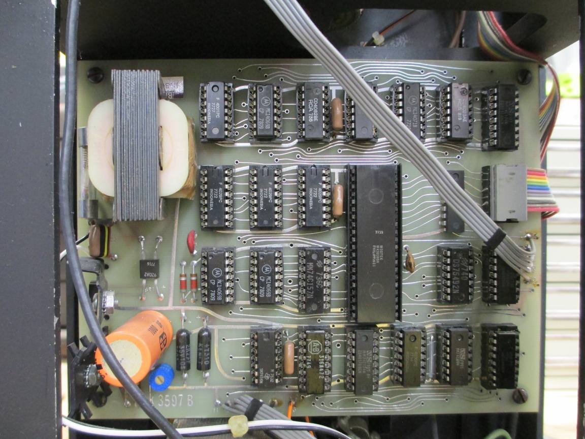
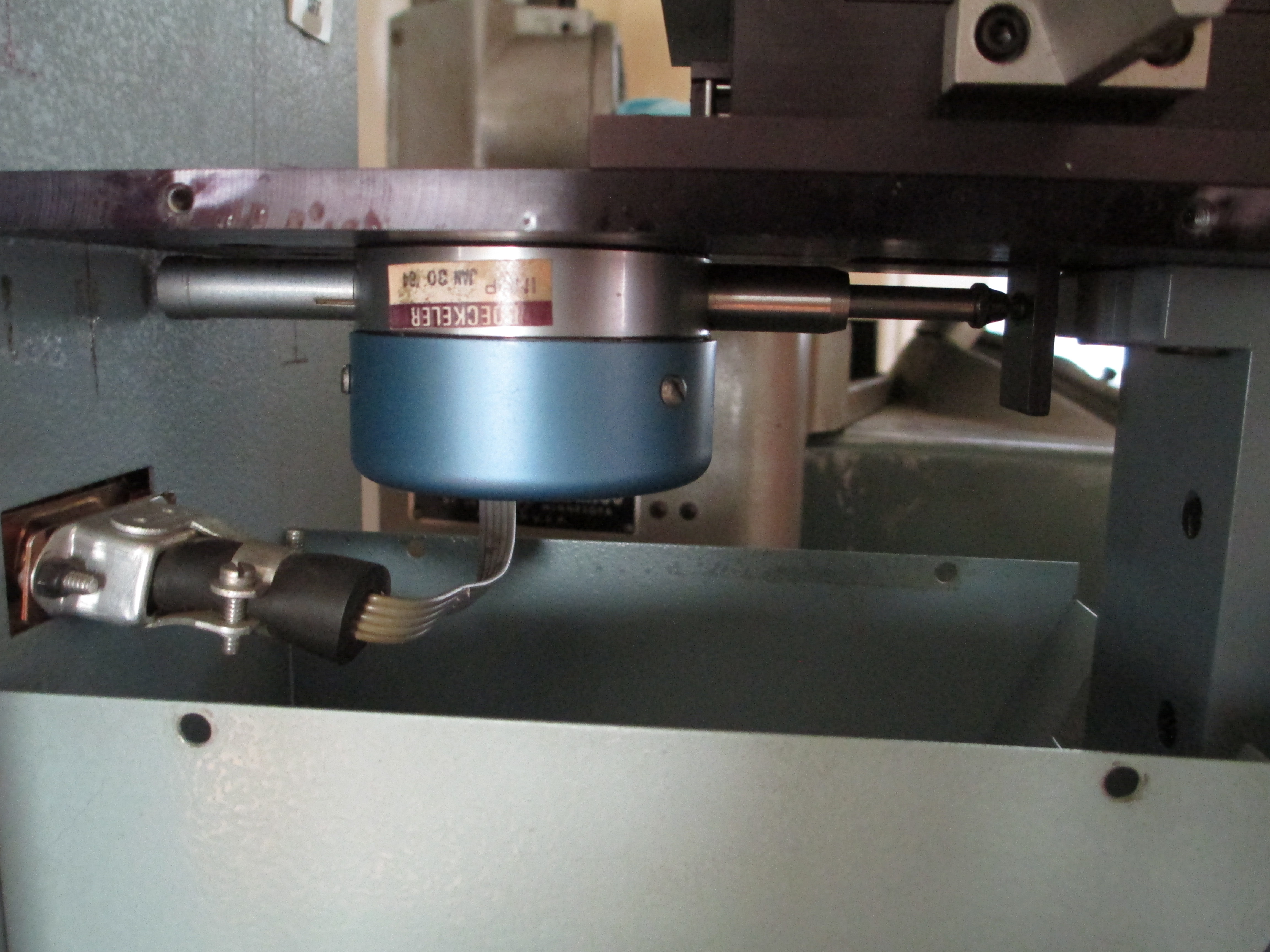
The stage was mounted wrong- 50mm too high, so the setscrew fell on the finished surface of the mounting column rather than in the groove provided for it- and took a two ton jack to remove (the setscrew raised a huge burr on the mounting bar.) The electronic readout was dead (still working on it. 1970’s discrete technology. All 7400 logic. The actual problem is a bad transformer and blown grain-of-wheat lamp in the optical quadrature measuring unit. I may roll my own or use a modern replacement) But it turns out this unit may have a history.

Not a lot of them were made. Ok. A lot were. But they were made in Japan. Some were imported and rebadged by EPOI, and, at the same time, fit with IKL (Boeckeler) readouts after it EPOI became Unitron. Bodge job, but they worked. Some of these were sold to US government labs. Including the FBI lab. This one has an ID etched in the case that indicated that is where its first home was.

The FBI lab used a unit of this model in the 1970’s when they redid the MLK investigation at the federal level. I don’t know if it is the same one I now have, as the serial number isn’t in the report, but it is possible.

I thought that was kind of cool.

It is sitting on a Snap-on (relabeled Kennedy) side cabinet of similar vintage (1970’s) on a stand I made up from box tube and painted to match. The adjusters for the feet were also made using the Nomad (except tapping threads). The cabinet was painted with a color know as “Pandemic Least Offensive that Home Depot Had in Stock”. It matches the shellaced plywood I put on top, so I may keep it.

7 Likes

Very nice write-up !
I’m curious and not familiar at all with the use of those vintage comparators, care to explain how one uses them, possibly with a pic of what they look like in action ?

3 Likes

Short summary: they are general purpose tools for measurement and inspection of parts and features roughly at the scale from about 0.1mm to about 100mm.

In inspection tasks, they often use overlays on the screen for visual comparison to tolerance limits (hence the name comparator). In measurement task, overlays or scales may be used for direct measure, or the micrometers on the stage may be used.

Detail:

(all of these pics were for a series of lessons I wrote up as part of a CAD course)

First, the use of a scale. This is at X10 magnification to a 6" (150mm) screen, so the largest feature that can be handled this way is about 15mm. Here, I was trying to identify the thread for a screw. The EPOI only does surface illumination. It is kind of like an old-school opaque projector.

Here, the thread pitch is about 0.75mm, but not exactly. Turned out the screw was imperial. It was from a different optical tool that has threads in a mix of metric and imperial, standard and unique.

It could have been measured with the micrometers using the crosshairs.

It is more accurate, but not always real convenient. The line-of-sight to the mic scales isn’t great, and I haven’t taken all of the backlash out of this yet (maybe 0.25mm for the y axis, and 0.20mm for the x), as the original provision needs repair. The screen rotates for angle measure, which is a common feature.

Lets see it in use on the S-T 14 inch (350mm). The largest feature for direct measure on the screen here is about 30mm. A little is lost at the edges for optical reasons.

Measuring the included taper on an adjustable parallel, again using surface illumination. This uses a 500W lamp, and is rather uncomfortable to use in hot weather:


The angle is 10 degrees, 0 minutes. Yes, the vernier is slightly mis-matched, but is better than the pictures make it look.

The part was translated using the stage micrometers, which were also used to measure the edge. There is no other easy direct way to measure this edge due to the angled face.


The edge is 7.40mm

Where the comparator shines (pun intended) is profile projection (shadow-graph is another term). The illumination is axial, telecentric, and directly toward the objective lens. The head at the top here provides illumination and the profile of the part is very clear. Telecentric illumination means that the principal rays are all parallel. For illumination purposes, this gives clean edges with (little) glare from light reflected from surfaces making it to the objective. It also requires a lot less power, since the light is direct, not reflected:


This dovetail is near impossible to measure any other way. Telecentric lenses are also used for imaging, as the field distance doesn’t affect the size of the image. Transits and surveying levels use telecentric optics, generally. Compare that (again, pun intended) to the same part using surface illumination:

In this case, it is tough to locate the plane of the dovetail exactly, due to the imperfect edges. The other end was worse.

Setup and fixturing has the same concerns as for machining. Vee blocks, clamps, magnets and stands (at in the picture above), bench centers, and so on are all used. The reason I have the Snap-on cabinet is primarily to hold all of the fiddly bits for these machines. And to raise the EPOI high enough to be easy to use. Also note that the micrometer heads on the S-T are not the original. Those are direct-read to 0.00005" with 50mm diameter thimbles. Unfortunately, the travel is only 1", so a gauge block needed to be inserted (standard method, just like on a jig borer) for larger travel. And inches. I swapped them for 50mm travel, 0.005mm heads. If I need better accuracy, I can put a dial indicator on the appropriate axis, but using the 10X lens, that isn’t really meaningful. With the 50X lens (or 31.25X, to make 1/32" on screen represent 0.001"), more precise measure becomes meaningful.

The pure optical units are still made, still expensive new, and still useful, but the digital machines have mostly taken over. They take less space and, well, digital. Less skill is spent on the device, more on the meaning. Older pure-optical units can be had fairly cheaply. They list high, but tend to sell low. The S-T seems to list for $500 to $1500, or more, on a certain auction site, and this is a smaller, non-premire make production floor unit. They sell for $100 to $200 in practice, often needing clean-up or repair. J&L units list a lot higher, and sell for more.

Mine came from a race team’s engine shop. They were all heavy smokers. After several years, tar is still seeping out of crevices inside, but after the first year or so, the most volatile components were gone and I didn’t need to clean the mirror every couple weeks anymore. A daunting task, as the mirrirs are all first surface. Fortunately, they are not in a focal plane, so they need not be perfect, but scratches are still bad for the image quality.

The curtain that came with it got tossed in the shed. You could smell it outside. The bugs in the shed all died. For practical purposes, it was cloth soaked in black-leaf-40 (40% nicotine insecticide). It was eventually disposed of.

The lamps are the hard part. All obsolete. I converted the profile illuminator to a modern lamp. when the surface illuminator lamp goes, I will need to do that one as well.

These are both vertical units, but there are also horizontal ones. Each type has advantages, but I am already running long.

EDIT: I didn’t not it, but the first photo above, measuring the screw threads, LOOKS like a profile illumination because the screw is in a vee block and things are oriented so the illumination (mostly) reflects from the vee. The vee surface looks light since it a a ground, unpolished surface adjusted so the grind lines provides the illumination I want. Turn it five degrees and it is darkfield. There are a lot of tricks to see what you need, many similar to those used in conventional optical microscopy.

7 Likes

Fascinating! thank you!

Short follow up example of use for measurement using the digital read on the EPOI unit, and why I had to fix it.

This is for the measurement and electronics geeks, especially those with an interest in the history (I finally finished the repairs- Go figure for a 1977 unit: transformer failed and a cap was marginal, so I had to repower the logic board. No microprocessors, all discrete 7400 series, a couple 4000 serice CMOS, and one Mostek BCD-to-7-segment driver. All off-board connections are wires soldered in, so I redid them as well, since the hole spacing on the board matches no connector available today).

As it was when I got the unit:

Previous rework is visible in a few places, but I don’t know how much was the modifications to make it fit this unit. The electronics appear to be most of the guts of an IKL ‘MicroCode’ readout unit (still made by Boeckeler, but several iterations more modern. Boeckeler was a division of IKL, formerly a division of someone else. Boeckeler is still there, but the former parent seems to be gone, and they now own RMC Microtomes. Go figure.).

The readout pickup is an electronic dial indicator (roughly as it was on arrival) for the y axis (only one axis here-- Back in the 1970’s, even this was about $US1000 and still a new thing):

Factory refurb in 1984. No fancy electronics here. Just an slot-wheel where the pointer would have been, a grain-of-wheat lamp for illumination, and quadrature output to the logic board. The same interface as their digital micrometer heads, hence the big hole that serves no purpose here, in the middle of the circuit board

The two white adjustments to the right side of the board are voltage divider potentiometers. They adjust the A and B phase threshold reference levels for the 393 comparator. They needed to be set, as well, and I had the cover on and off about a dozen times to do this. Turns out that if the cover is off, the ambient light is enough to shift the needed threshold. Fun times, back then.

In use:

Here is the funny thing. The shots below make it look like the digital unit is off a little. It isn’t.

Metric:


To measure, line the crosshair with the feature of interest, set zero, move to the next feature, and read the display (or the micrometer head). The edges, location, and width of the marks on the scales have more variation than the resolution of the reader. This also illustrates why the part I put in the contest was needed. Gotta be able to a) get the part in focus, so I made a variety of risers, and b) gotta be able to adjust the angle of the part to line up with the axis travel (I aligned the screen during reassembly so the angle vernier is a match) This is pretty much the case for any comparator, including modern digital imaging units. Horizontal types are easier for many things, since the table and fixturing give you one or both axes once the machine is aligned.

The little white button next to the display sets zero, like on a digital caliper.

Color of the lettering is so close to the color of the paint as to be unreadable in practice. MUCH more contrast here since the camera did contract and color balance. For the unit select switch (top right) you kind of just need to know.

Inch example:


These machines are likely to show up again in Nomad projects, since I realized during work-from-home there are a LOT of general fixtures I should just make up and have. These got a lot of use developing lessons and guides for students.

4 Likes

Gotta love vintage electronics :heart_eyes:
Those snake-like PCB tracks, it almost art!

2 Likes