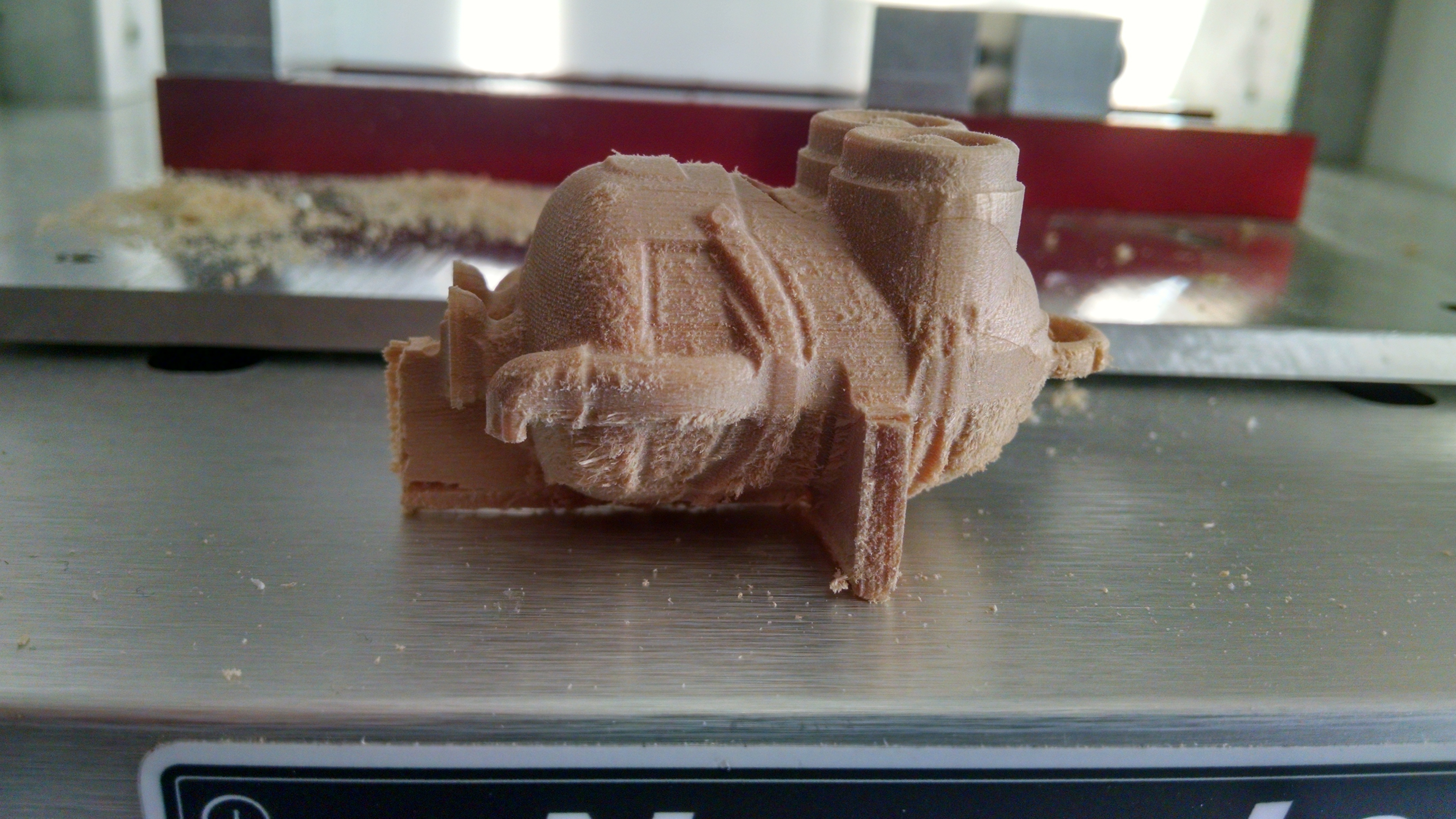
So, I’m making forays into 2-sided machining, and slowly making progress. But my last two attempts have produced something anomalous, and I wonder if anyone else has seen anything like it.
Now, I tried this twice, once with the supports at the center of the geometry, and once at the bottom of the geometry. But in both cases, the supports were cut as if the “bottom” NC file was not reducing their Z dimension at all. Instead of .125" or so, the Z dimension of the supports is nearly 0.5".
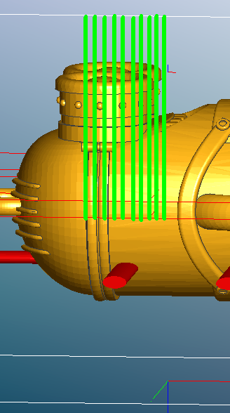
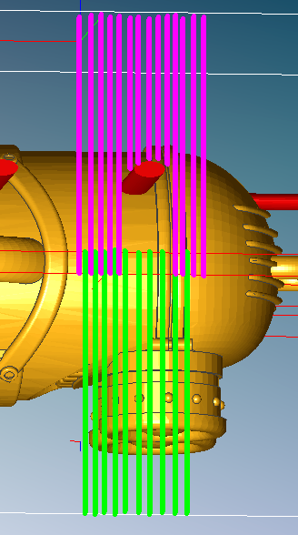
(I just realized, that screenshot is from an earlier version with more supports than I ended up using, but the support dimensions as shown in MeshCAM are correct to the ones I actually used).
I didn’t have this issue on any other models that I’ve tried doing 2-sided machining on. Could this be caused by the model, or could I be causing it somehow in the way I’m setting up the supports?
@SkyeFire, that is a puzzler. In general, it is best to put the supports at the widest point of the geometery (which would be the “parting line” if the part were molded) to minimize shadowing what would be undercut areas. And you need to set the maximum depth to be deeper than the supports from each side. If the supports are much shallower or deeper than the center of the stock, this might mean running the 2-sided toolpath calculation with different max depths and keeping only the top toolpath from one and the bottom toolpath from the other. In your screenshot with the supports, it looks like you are machining just past half-depth, but the supports are markedly deeper than the max depth you’ve defined.
Assuming you are doing the machining with a ball-end mill, and place the supports on the “parting line” around the part (that might mean 2 or 3 trips into the support dialog to specify different vertical positions), you can leave max depth at the bottom of the stock and choose Machine geometry plus with a margin of just less than half your tool diameter (maybe .120" for a .250" cutter). The cutter will machine as deep as the widest part of your geometry, and not quite fall off the edge. I have used that technique a lot on irregular workpieces.
Yeah… the supports right at the Z mid-point interfered with some of the details, so I experimented with lowering them slightly. When that generated the super-thick supports, I tried moving them to the bottom of the geometry, with no real change. I could see why the “shadow” of the supports could create the big supports when I set them at the botom of the geometry, but I got the same effect when I only had the supports set 2-3mm below the parting line.
The roughing was done with a .125" flat mill, with the finishing passes done with a 0.063" ball. The max-depth setting overlapped by about 2mm past the parting line – I couldn’t do full depth, b/c the stock was too thick for my cutter to reach all the way through.
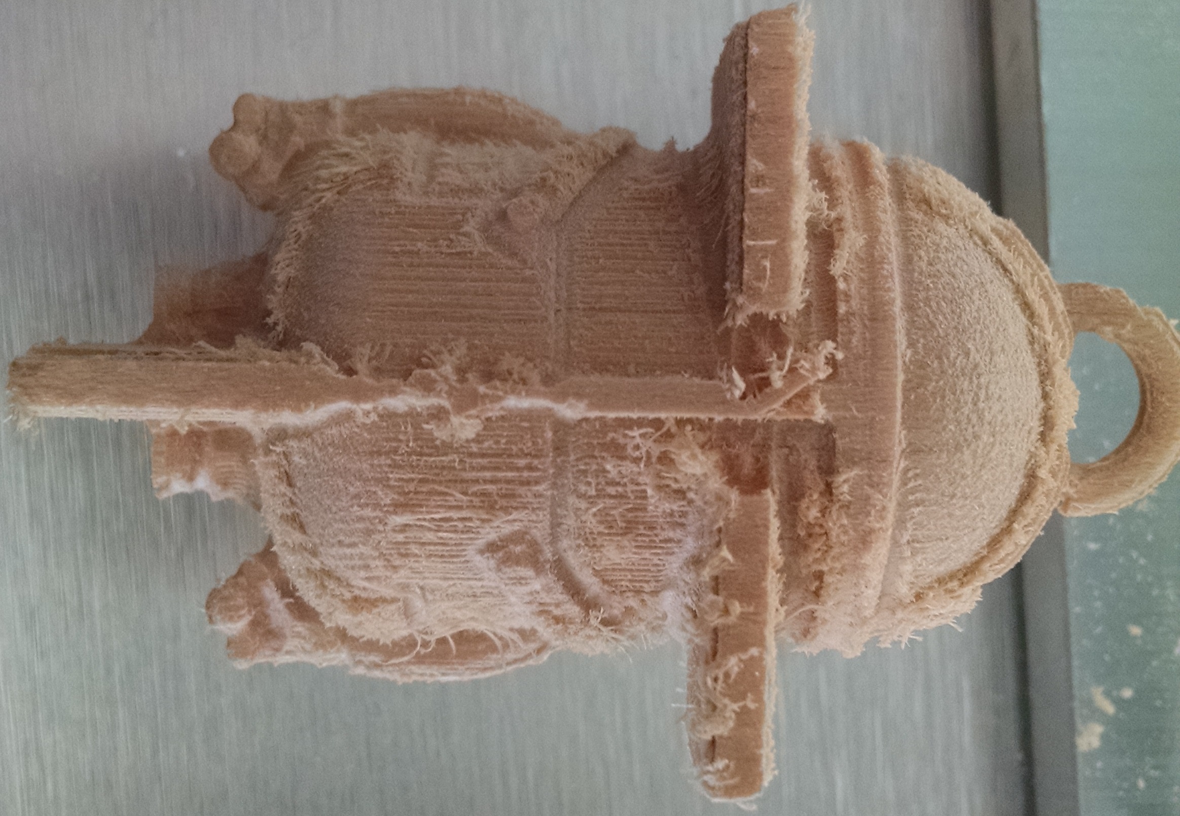
There is the area (now) below the support that was too deep to machine from the top side, and now is shadowed by the support from the bottom side, so it is not machined at all.
That looks about like the effect shown in your photos…
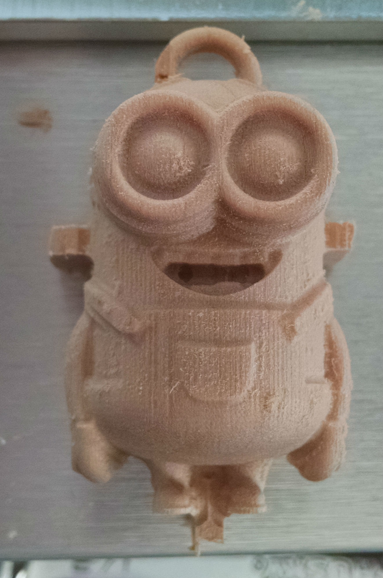
I’ll add that in your last photo in the first post, you must have put the supports at the bottom of the geometry. That is the bottom-most of the geometery at any point, and not the bottom of the geometry where the support will touch. In your model the goggle strap defines the bottom of the geometry. If the geometry is not flat on the bottom, you’ll need to hold the supports up a little from “bottom of geometry”. This is a different effect than the “shadowing”.
Well, it took a while to find the free time, but I’d say you were correct, Randy. A version with the supports at the center of the geometry’s Z dimension avoided this problem entirely.