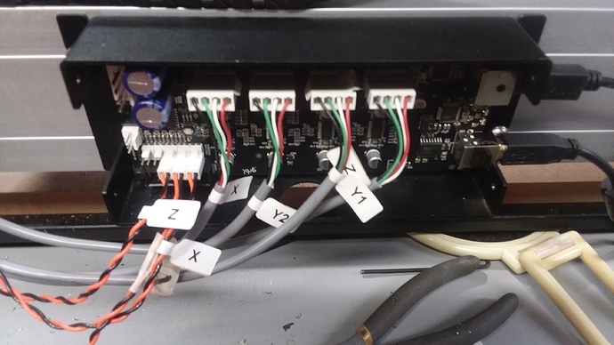
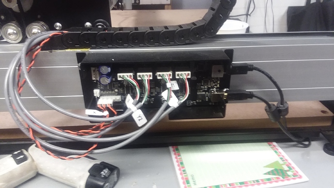
I received an e-mail from tech support saying that I had the limit switches plugged in backwards. Instead of plugging them in on the right side with 4 pins to the left I had them reversed. I was happy to hear that would finally solve my problems. So I went to the shop and switched all the connections started a new session and started the homing process. Z went smoothly and then the X axis started to move very quiet and smooth and then that dreaded noise started about 2/3d’s of the way down. Right now I’m thing that replacing the harnesses is the only solution.
Will I have been trying to call to have this problem resolved but as usual no one ever answers.
No reply to my e-mails either.
I know it’s frustrating, bear with us. I hope I’m not treading on carbide 3D support’s feet, but may I recommend you try the following, so that we determine if there is actually something wrong in the wiring or mechanically, without having to rely on the homing procedure only.
-
I will assume that you have checked that when the machine is not powered, and you move the X axis manually (slowly), you don’t feel any issue, it’s all smooth (if you are going slow enough that is, else the current induced in the motors may temporarily lock the motors and you feel a “bump”)
-
To try and jog the machine WITHOUT having performed homing (FOR THE SAKE OF THE INVESTGATION ONLY!),
- download and extract Universal G-Code Sender (here) somewhere on your PC
- go to “bin” subdirectory and launch ugsplatform executable (the .exe if you are on Windows)
- click “connect” (little plug & socket icon)
- click “unlock” in the “common actions” panel. No need to home.
- go the the “jog controller”, choose a step size of say 10mm or 1inch or whatever
- now click on the left X arrow, and see if your machine moves to the left correctly. Repeat, until you reach the location where you noticed that grinding noise previously. You should be able to use the jog arrows and small step sizes, to figure out if the problem appears at a specific location, or only when jogging a long distance, etc…
- post a pic of your wiring and video here too, someone may notice something odd
TY I will give those suggestions a try and post the results.
I meant to share here. Many eyes…lots of help.
compared to my XL this seems mounted upside down…
(not a huge deal just all pictures in the install manual need to be rotated 180 degrees)
I thought so. I was told that I received a machine tha was built before the updates. There are a lot of pic’s that don’t match my machine
it does not look like your limit switches are in the right order; upside down they should be open-open-z-y-x, an on your picture (bit hard to see so I could be wrong) it appears open-open-z-x-y
This is the e-mail from tech support
Hello Robert, I took a look at your photos and it seems the motor connections and limit switches are plugged into the wrong spots. The board is mounted upside down from what the directions indicate which is up to preference. Here are a couple photos that show where the items should be plugged in.
Thanks!
–
Nicholas Meastas
support@carbide3d.com
Can you tell me or send a pic of how they should be connected?
how determined are you to have the USB / power on the right side?
since if you don’t care it’s trivial to just unscrew the board and flip it over…
that way you should match the documentation again
yes but your board is upside down…
OK so I will reverse the board and then look at the assembly instructions?
that would be my strong recommendation; doing this upside down is… error prone
even if you later want to change it back, until it works I would flip it over so that it matches all our machines and the instructions…
I assumed the letters X Y2 Y1 Z to locate the motor plugs should be right side up not upside down.
Would you know why Carbide 3D would be closed at 3:30 their time? I call and the recording says " We are currently closed" They never answer the phone and leave their customers hanging.
Did you send the $X
Looks like you got the motors in the correct spots (assuming the other end goes to the motor as labeled on the wire), but your limit switches aren’t correct. The board is labeled…can you see the small text on the board?
Same as it says here:
https://docs.carbide3d.com/assembly/shapeoko/s3/#wiring


