Hey all, is there a way to raise and start a spindle before it plunges for it’s first cut? I’m trying to surface one slat at a time on my Shapeoko 5 Pro, I have everything set, but when I run the job after zeroing on the top of the slat it stays there and tries to start the spindle. I also noticed it doesn’t use the BitSetter, it just asks if I have installed the bit while staying on the work and has a Resume button.
When I ran the Hello World program with the marker it raises the Z up, then asks if I want to use the BitSetter or Resume, that’s what I want with this job too.
I think you need to look at the post processor for Carveco. Make sure you are using one that has the BitSetter in the post processor. Look at the Carveco forum to figure out which post processor to use.
Not likely. On my machine when you hit start the router moves to front and requests bit. Then goes to BitSetter, returns to front center and starts router, BitRunner, then moves to first plunge and starts cutting. If I hit pause the router stops running and rises up. When I hit start again the router plunges then starts on the way down and continues to cut.
I do have a BitRunner controlling my router. If you dont have a BitRunner you uncheck automatic spindle control in config and CM prompts you to turn router on/off.
OK, good to know, thanks for the info. I wonder if changing the post processor was all I needed and it will act differently. I will try running it tomorrow. I was using a .tap file, now it’s .nc. Mine was going to BitSetter, then dropping to the zero height I set and going all the way across the bed to the SW corner and then starting the plunge and stalling my VFD spindle.
.tap and .nc files are the same thing. gcode is just text. gcode can be opened in a text reader and is human readable. The only difference between .tap and .nc is the file extension. Now the contents of a .tap or .nc file can be very different based on the post processor used. When you create a CAD file in Carbide Create or Carvco those files are propriety to the company. However when you create tool paths and output them to a .tap or .nc file the post processor interprets the CAD tool path and creates the gcode that the Shapeoko or other CNC understands. So when Carbide Create creates the gcode and uses the Shapeoko Post Processor the capability of machine is used to add gcode commands that the gcode sender sends to the Shapeoko. Things like the BitSetter and other accessories.
Carbide Motion is more than a gcode sender. CM knows what kind of machine you have based on the configuration sent. So CM knows if you have a BitSetter or a BitRunner and reads the gcode and activates those functions and moves the Shapeoko to use those accessories based on the gcode contained in the .tap or .nc files. Those functions are put in by the post processor of the CAD software.
Carveco knows what a Shapeoko is capable of and writes their post processor to utilize those capabilities. So the most important thing any CAD program has the post processor to utilize the unique accessories of your CNC machine.
So it looks like that all worked. After it used the BitSetter is raised up, spun up the spindle, and started lowering as it moved to the southwest corner where zero was set. The only thing I noticed is that there are circles and it didn’t get everything. I set the work area 1" more than the slat, then set the exact size of the slat. Pictures below:
I ended up having to make the vector larger than the slat, and set zero completely off it to get the entire surface in one program. Other things I tried, like adding an extra box on the side to start in ended up leaving a small strip on either the left or right side of the slat. All this seems kind of silly, like it should be more accurate, so I know I’m doing something wrong since it’s a machine following orders.
I’m tempted to make a program to cut all slats together, so I don’t have to set the job up and zero X for every slat.
I have an SO3 with a supplemental spoilboard with 1/4-20 tee nuts. I purposely made my spoilboard smaller than the maximum travel of an SO3. That way I can surface my whole surface. The newer hybrid tables are larger than the cutting area on many of the machines. I think the SO5 is the only one that you can cut right up to the edge of the hybrid table.
As you found out you always need to make the area bigger than your actual slat to get the whole thing cut. If you made the rectangle for the pocket the exact size as a slot the 4 corners would have a little island left. The reason is for a simple pocket the machine starts cutting from the middle and goes out and that is an inside rectangle cut so the corners are not cut. Only on an outside cut can you cut the corners off and that is a contour cut on the outside. The radius of the bit is always left over on an inside cut. The only other solution and it is a bandaid is with the pro you can do rest machining. Rest machining cuts a pocket and you run another tool path telling it the previous size and pick a smaller bit and you get a smaller and smaller corner radius but still a radius. For flattening a spoilboard the rest machining is likely not practical but is doable if you have the pro version of CC.
If you want to make a supplemental spoilboard to put on top of your hybrid table, which you can put on on demand and remove if not wanted, I will attach an older document I made for the SO3 to make a supplemental spoilboard. The principles are the same but you may need to modify the measurements for your hybrid table spacing and if you want to run imperial or metric hardware.
Cool, thanks for that, I will give it a look and maybe make one. I do hate to eat up the bed.
As for the machine getting the ends, it gets the back end fine, but the front it misses about 3/4", the only way I could get it is if I do a gantry shift, which would require me to unscrew and rescrew a few times. Besides that the bed is 49", but the official cutting area is 48.
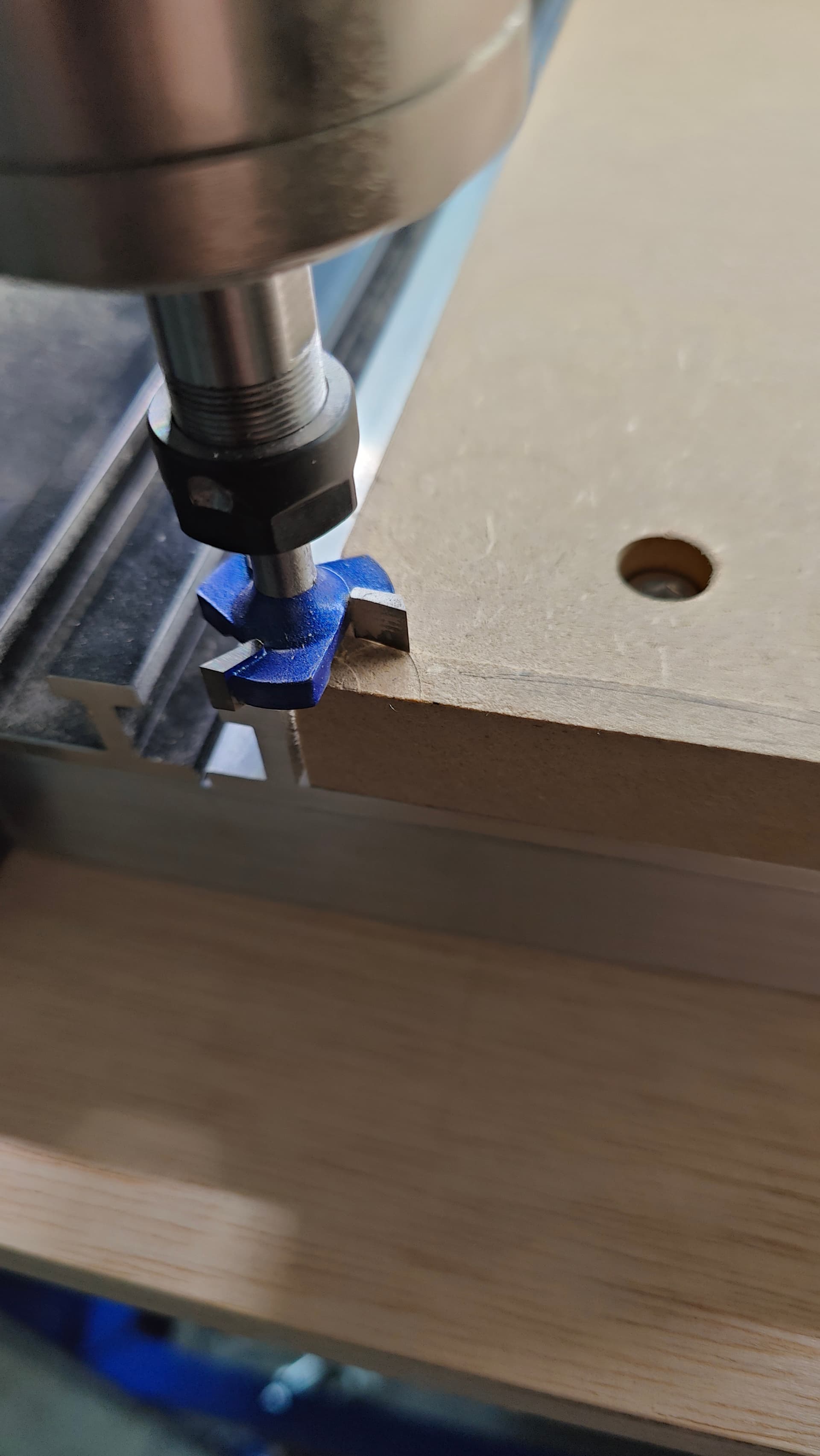
One thing I did discover after hearing a bad sound was that the BitSetter is in the way when cutting the last slat on the right side of the machine. My Sweepy ended up hitting the BitSetter, turning the Sweepy several degrees, and leaving a few inches not cut on that end. I ended up restarting, but used the BitSetter, immediately paused after Z rose, then unbolting BitSetter and laying it off to the side and that solved that issue. I could have moved that slat to another position, but figured the screws could have been tightened down just so, which could make the surface uneven and I would never get it back to how it was.
I will give your article a read, and the next thing I need to figure out is how to mount the VFD, the cord is WAY too short, even if I try to give what little slack there is, I can barely get it mounted sideways (not even vertical) under the edge of my bench. I mean JUST under the end because there is virtually no cord to work with. I’ve ready and heard other people complain about that too, bad design sadly… @WillAdams@wmoy, we need some sort of extension cable for the VFD, like yesterday.