One concern for doing joinery is that it requires the repetitive placement of elements — the new beta:
adds a Linear Array command which makes this easier, so doing a box is that much simpler:
Draw one side of the box:

Draw in a rabbet for the bottom (using more complex joinery across the bottom is left as an exercise for the reader)
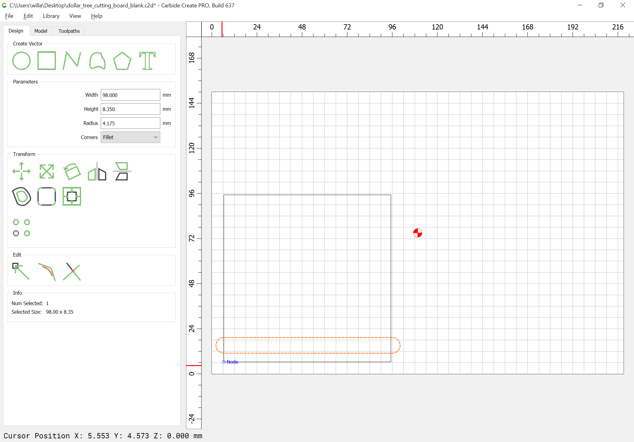
Draw geometry to measure the height of where the joinery will go:

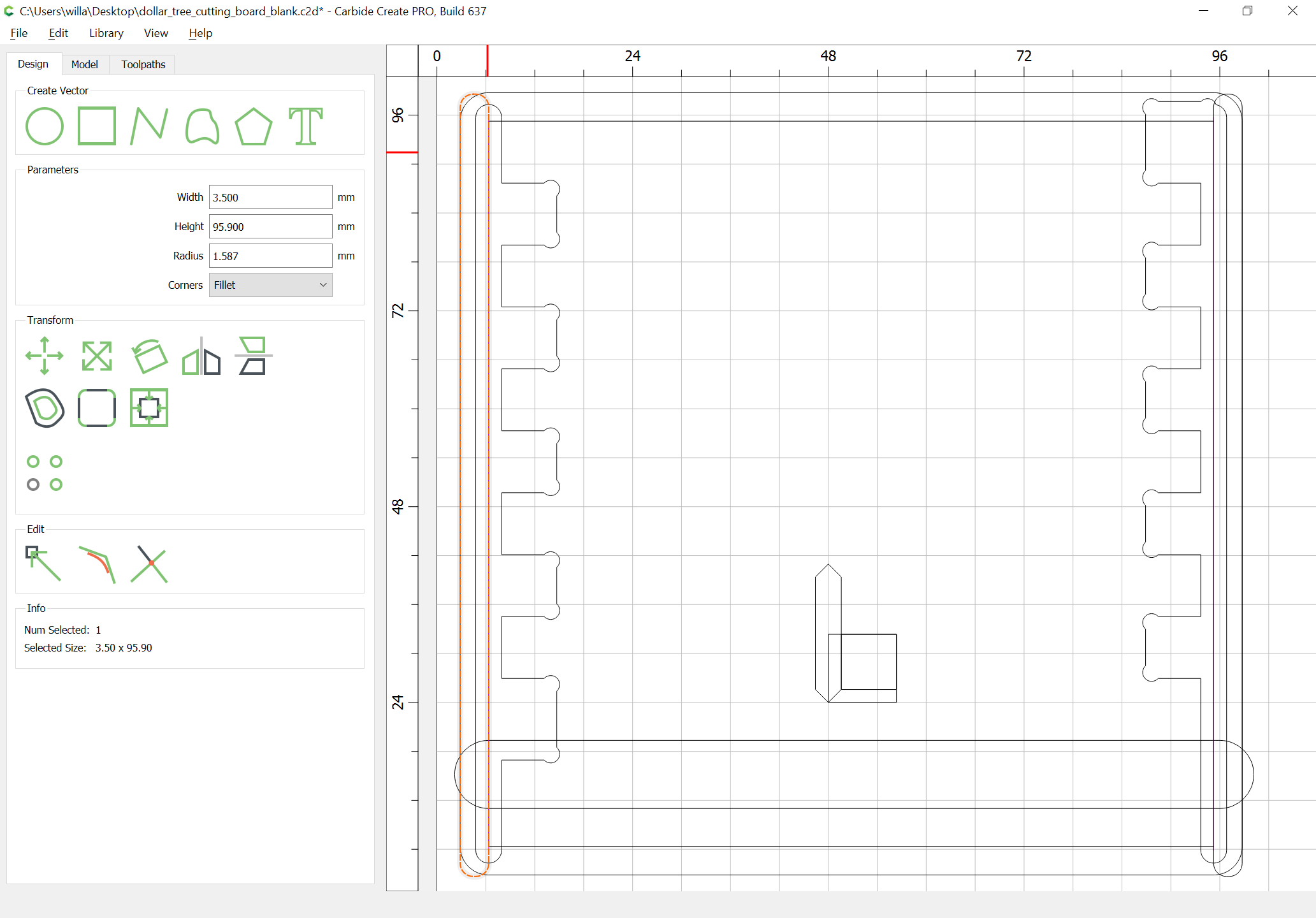
Based on the height, determine how many joinery elements there will be and their size — 10 seems workable so 75.9/10 == 7.59mm for height, and width is the stock thickness, 8.35mm in this case:

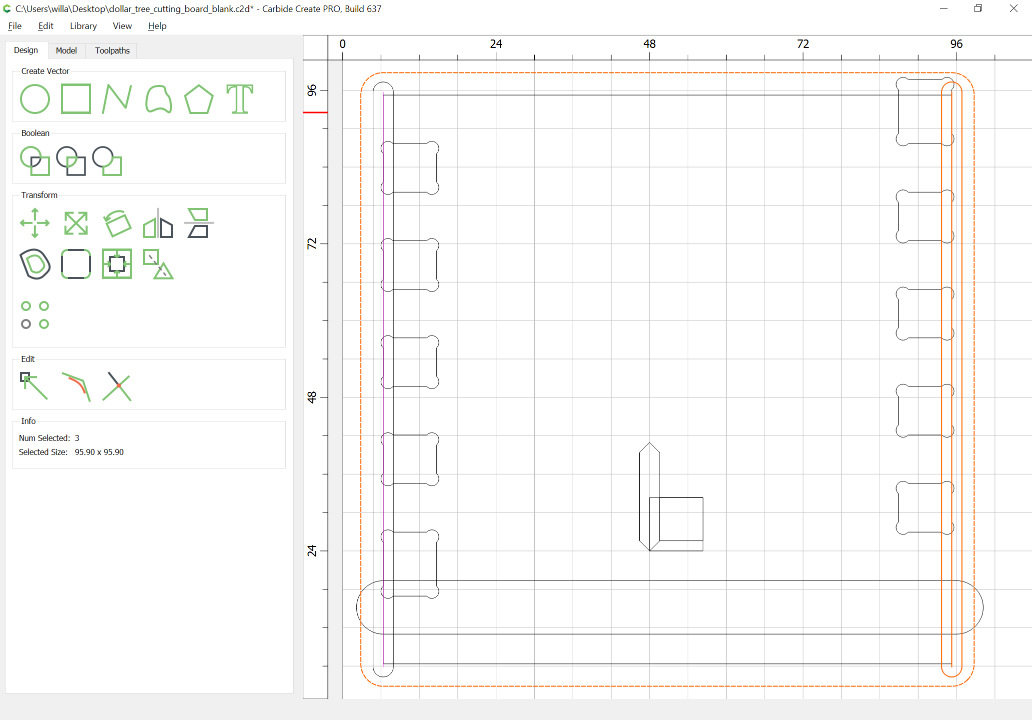
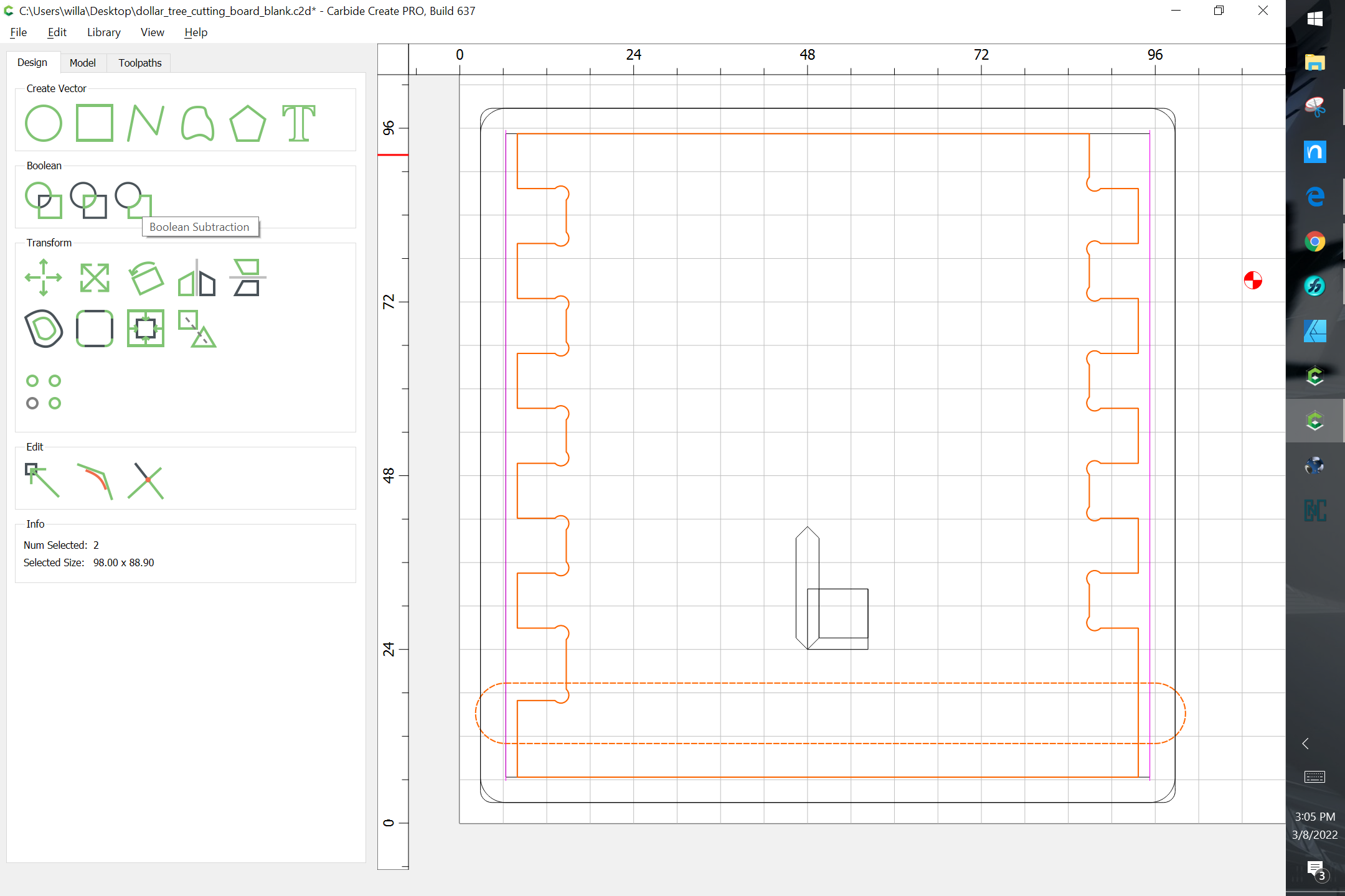
Invoke the Linear Array command:
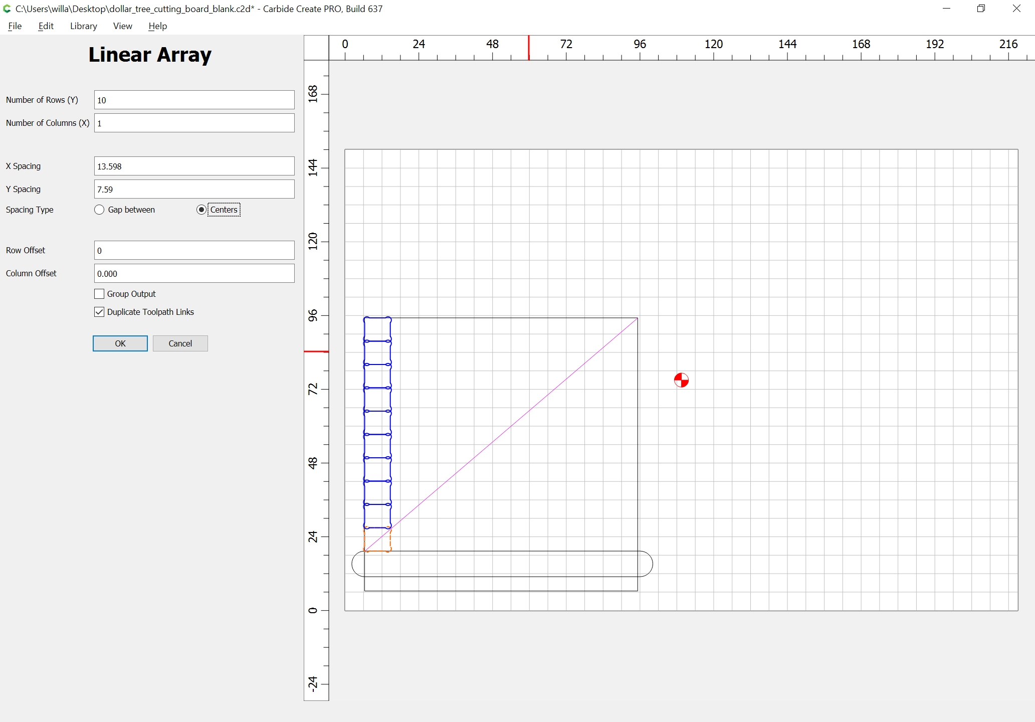
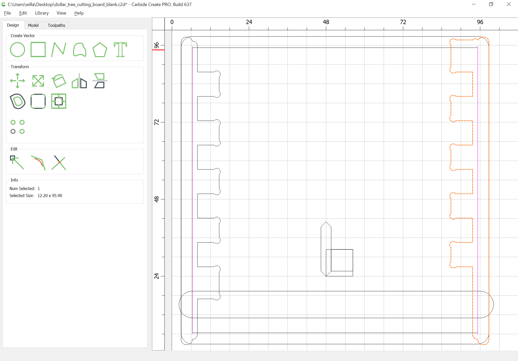
and set the number of rows (5) and columns (2) to create the number of elements needed (10) and set the X spacing to equal
part width (3.5in) - stock thickness (8.35mm)
and Y spacing to equal twice the joint height and the Column Offset to equal the joint height:
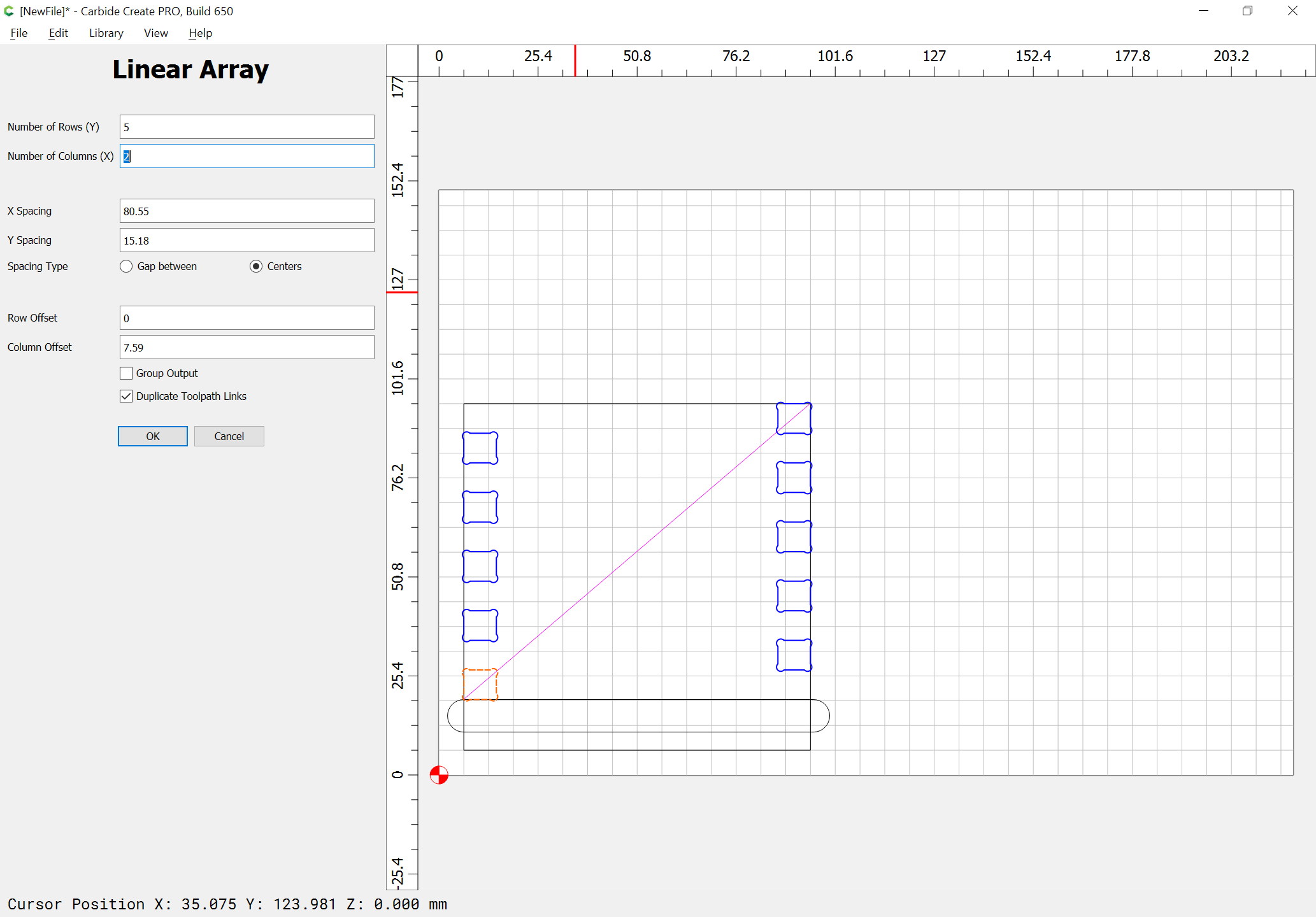
OK

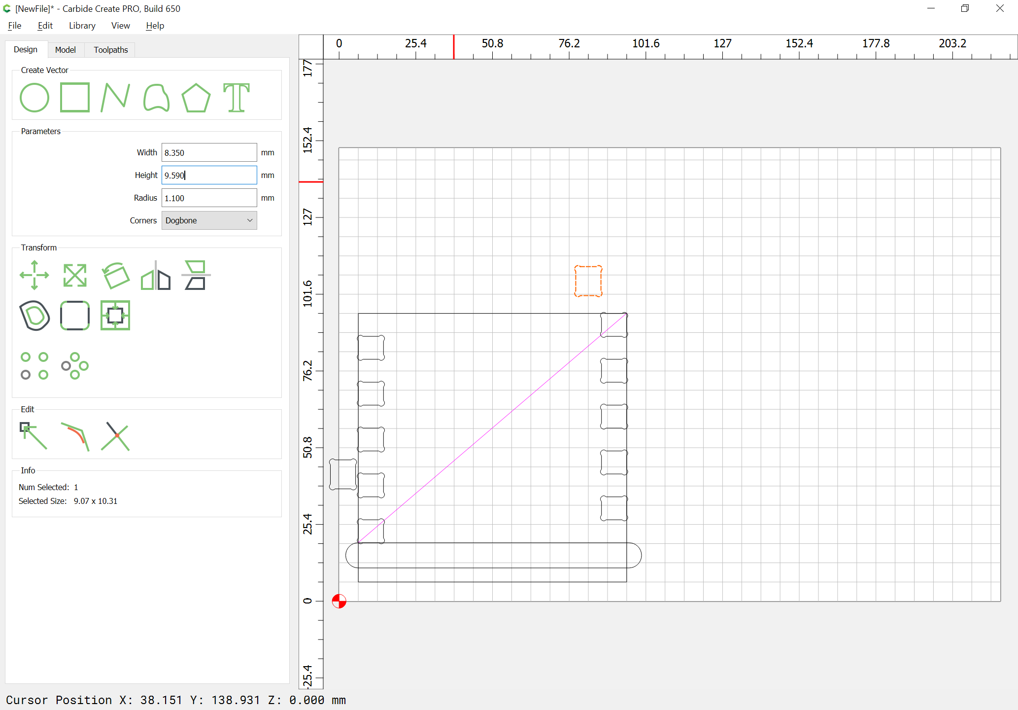
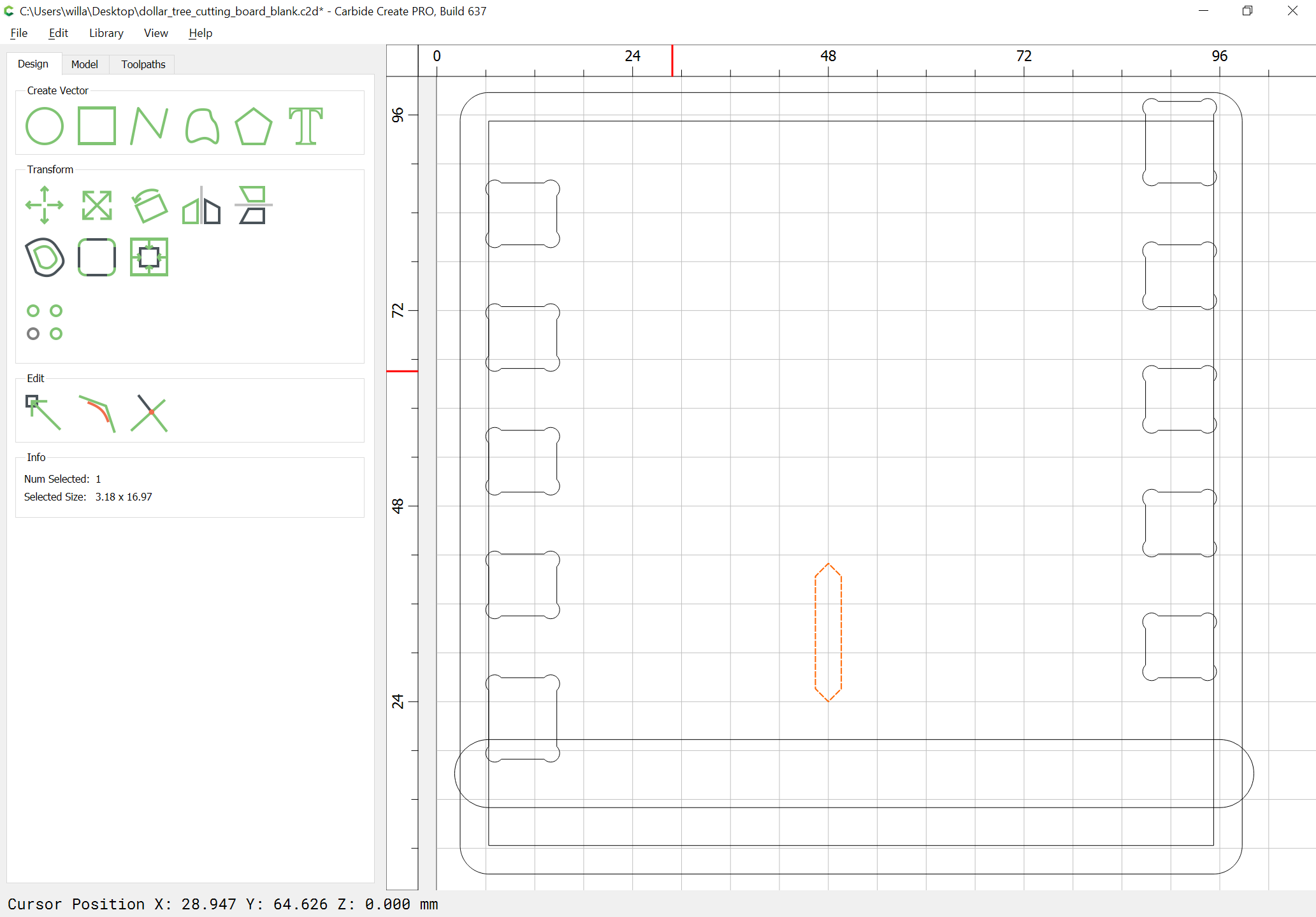
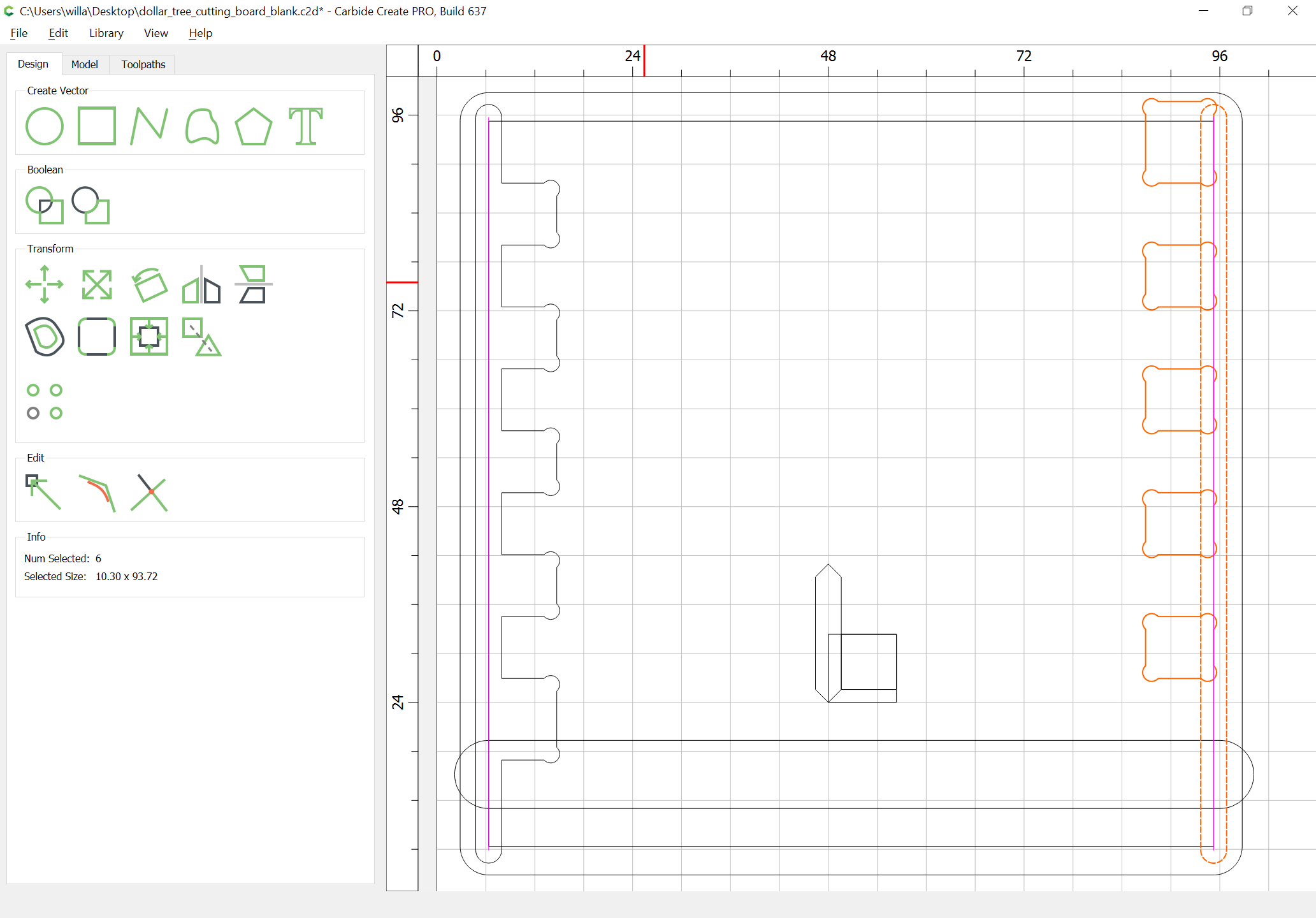
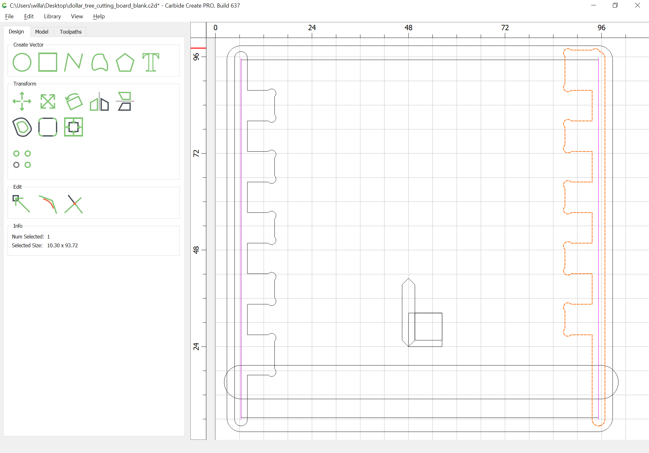
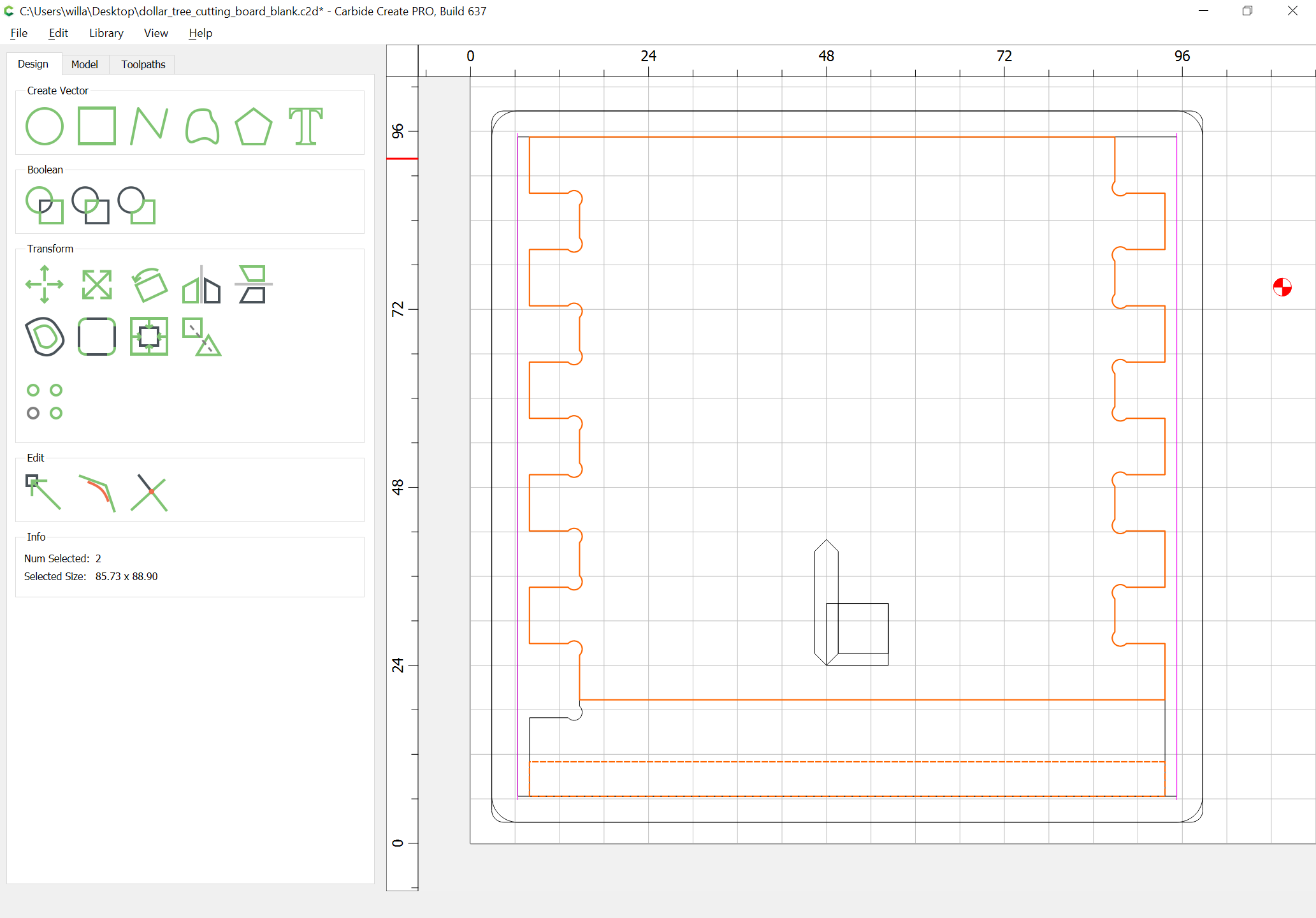
Duplicate two of the joint elements, and increase their height sufficiently to offset the dogbones beyond where they would show:
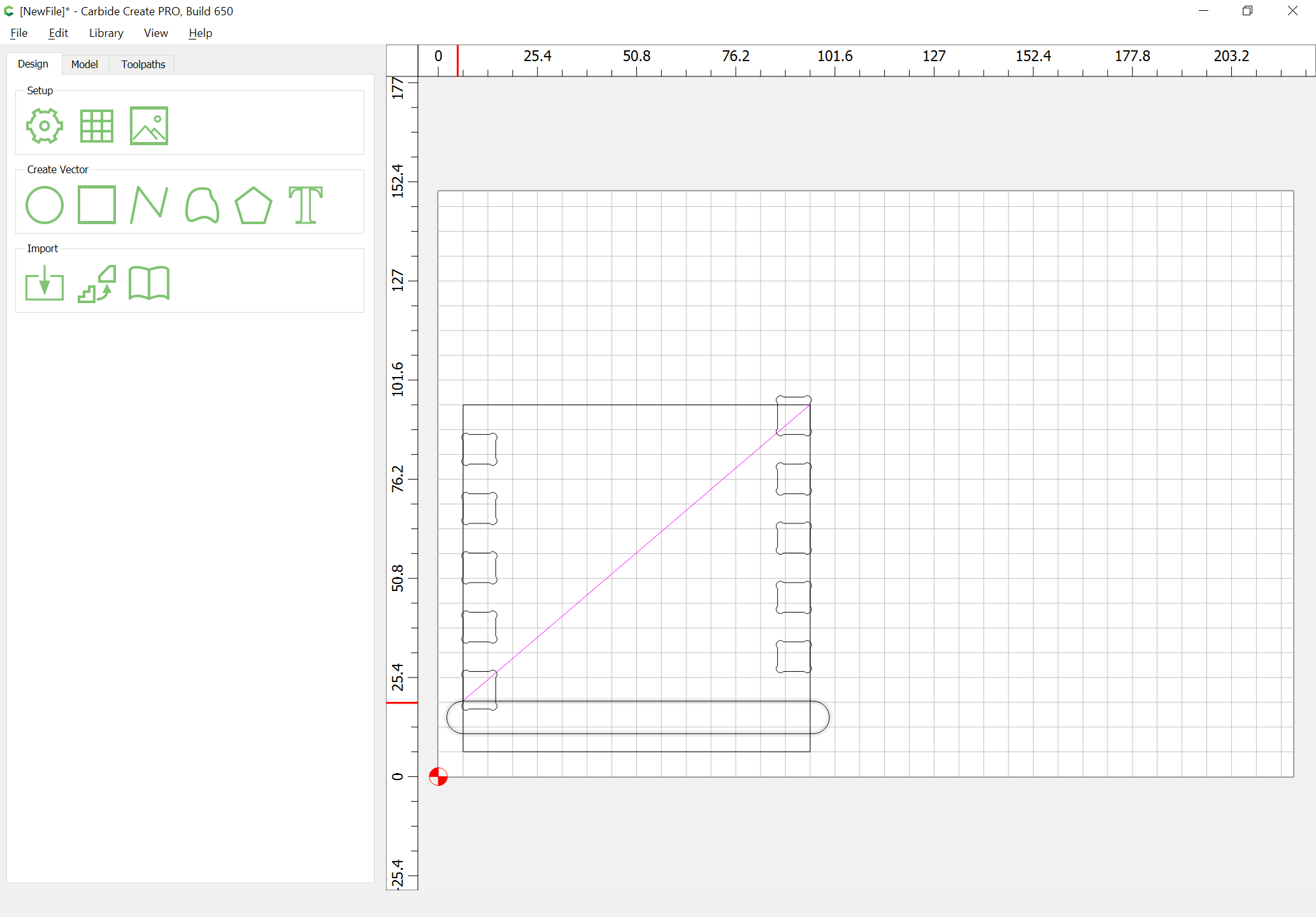
and drag them into alignment w/ the originals and then delete the originals:
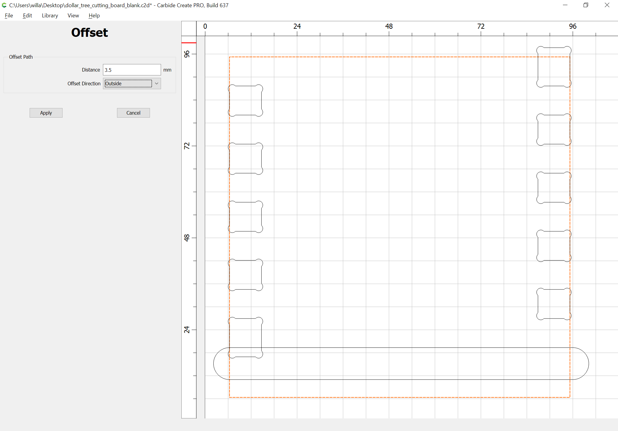
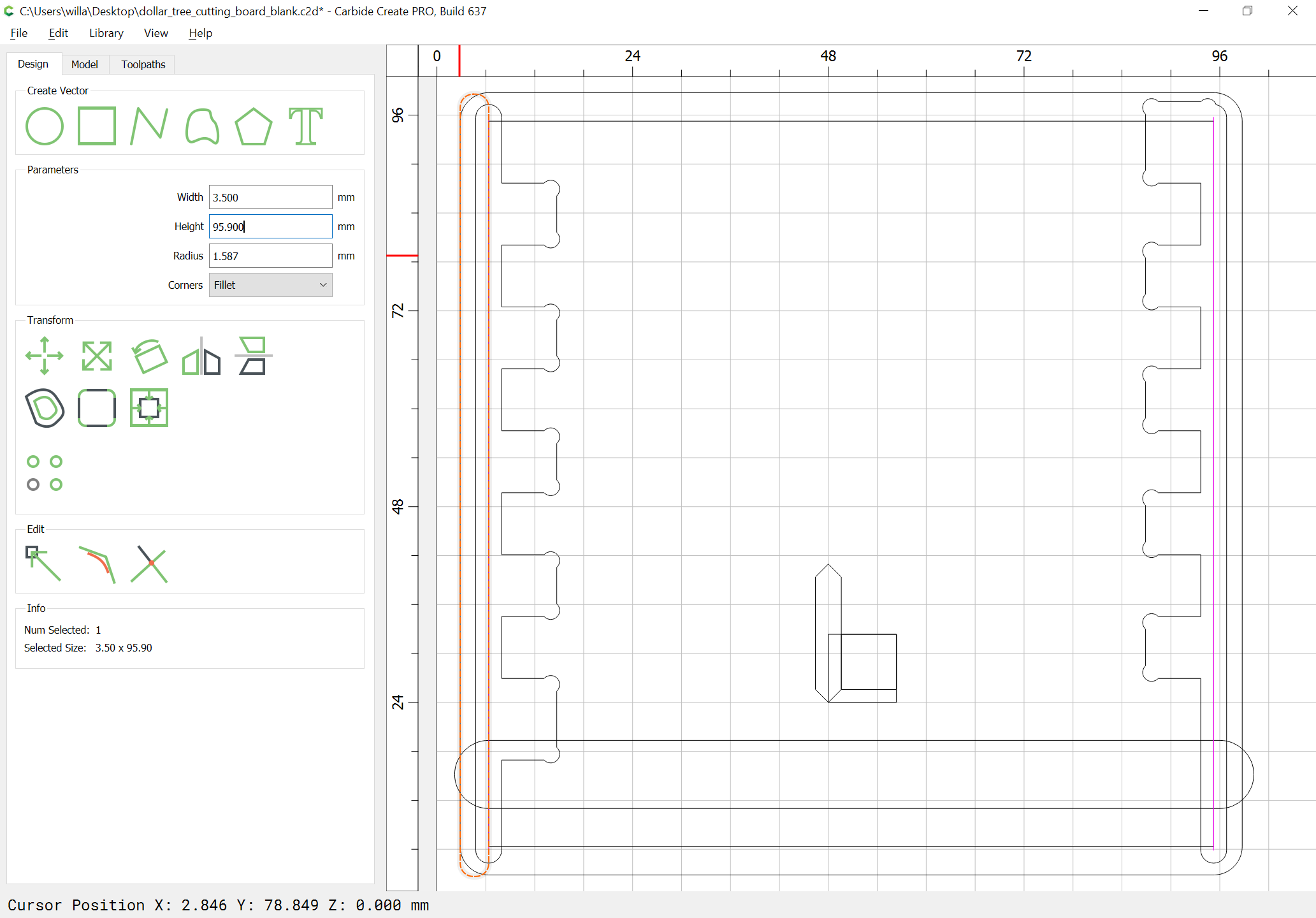
Offset the box outline by the diameter of the endmill which will be used plus 10%:

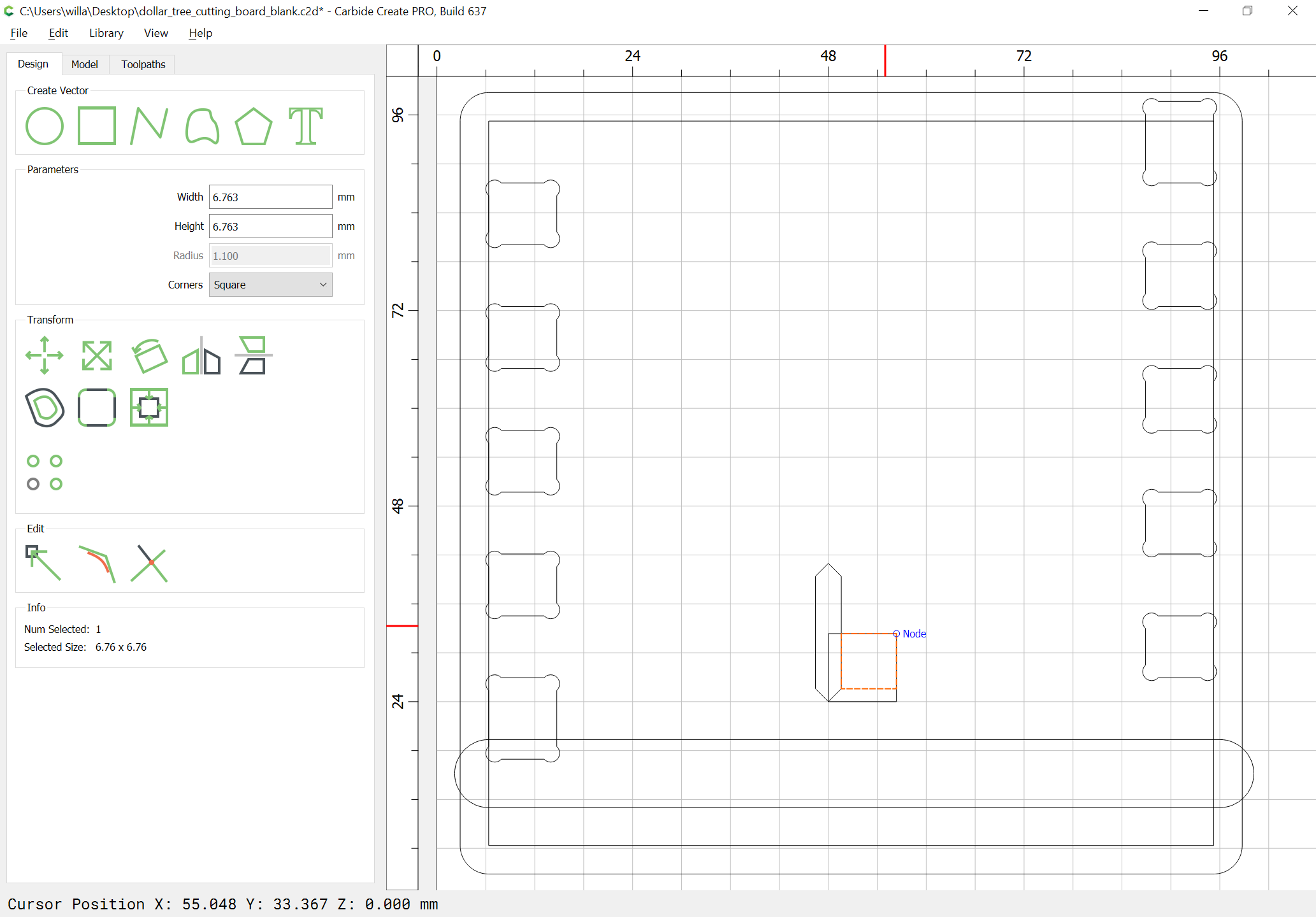
Draw up the geometry which will be necessary for cutting the miter:

and draw in a rectangle to allow calculating the depth of the fingers:
Then draw in the geometry for the miter cut — this has two be done twice — once, as an outline to Boolean union w/ the geometry, and a second time as a line for the actual cutting:
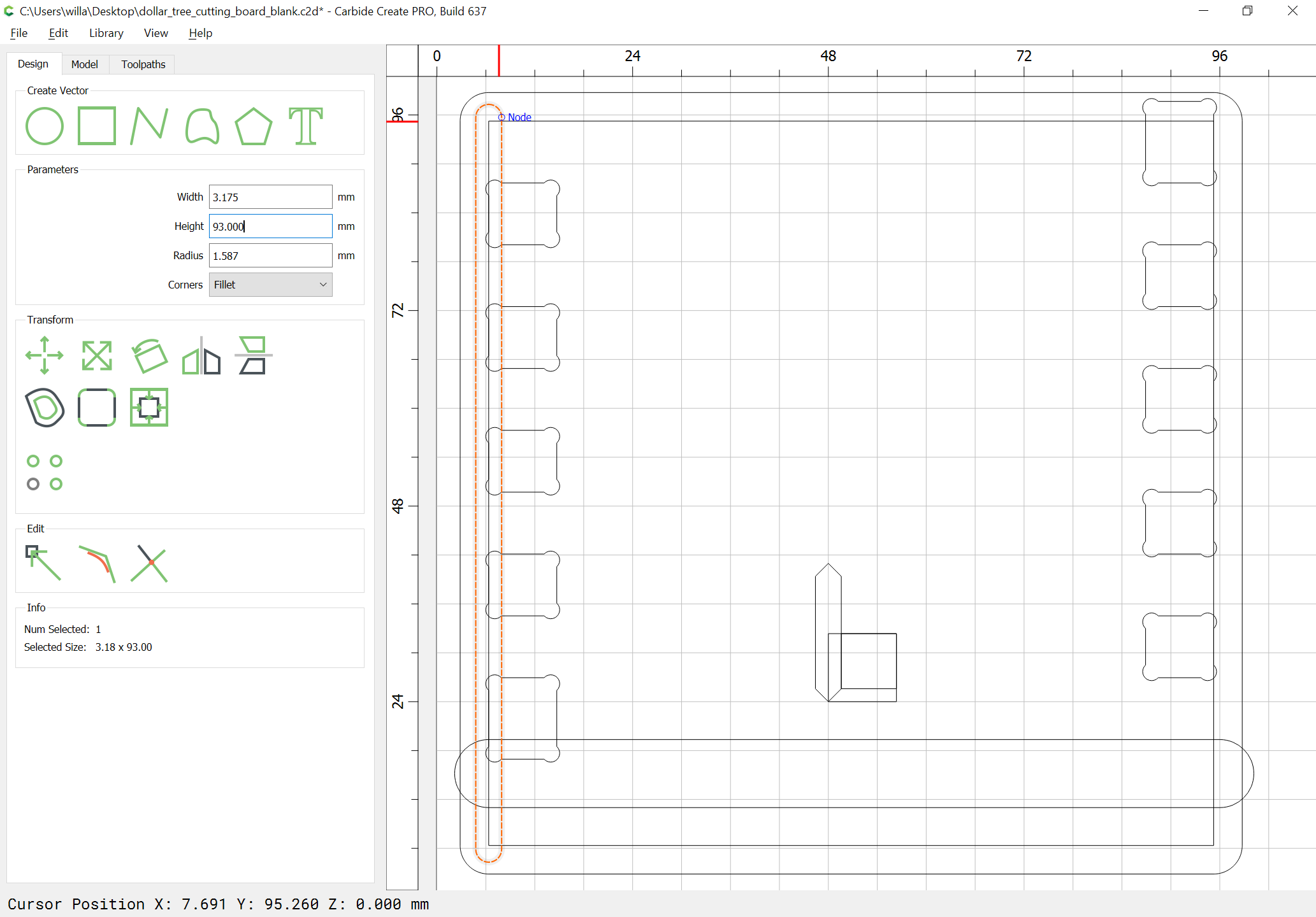

duplicate it, drag the duplicate into alignment w/ the original, then flip to the other side by also selecting the offset geometry:
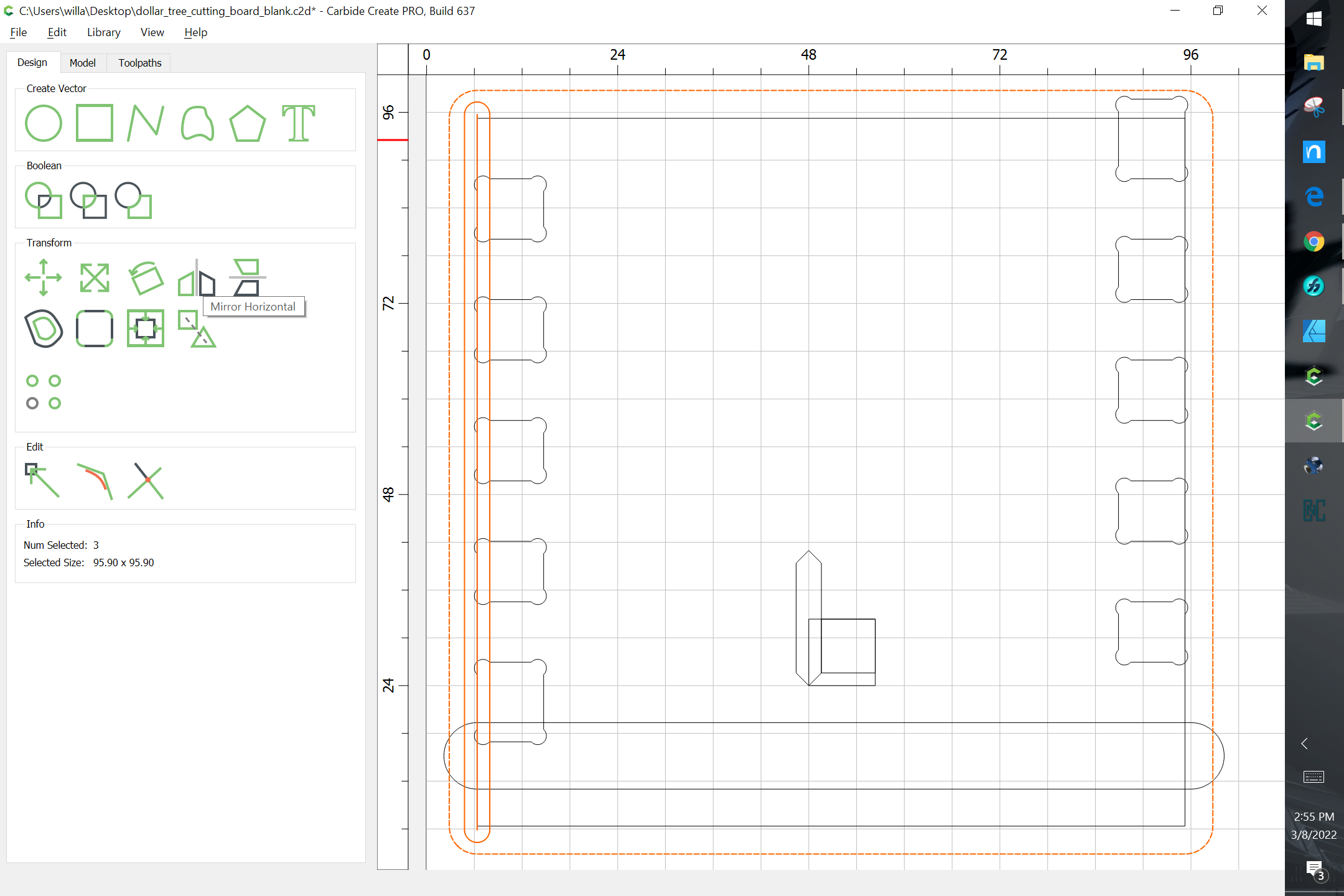
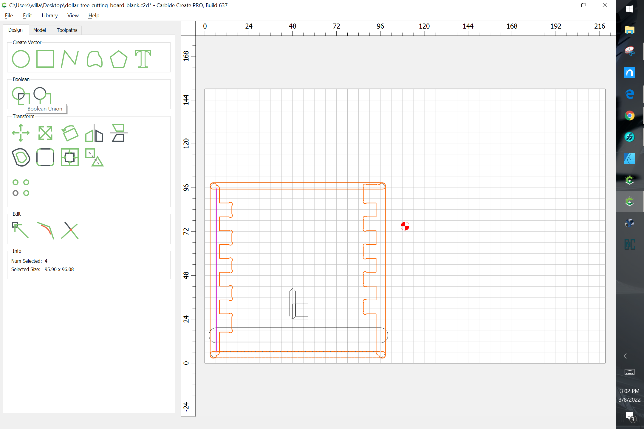
Union the rounded geometry for the miter cut w/ the joinery:

Draw in clearance geometry for cutting the sides:
union each w/ the geometry for the joinery:
Repeat for the top and bottom:
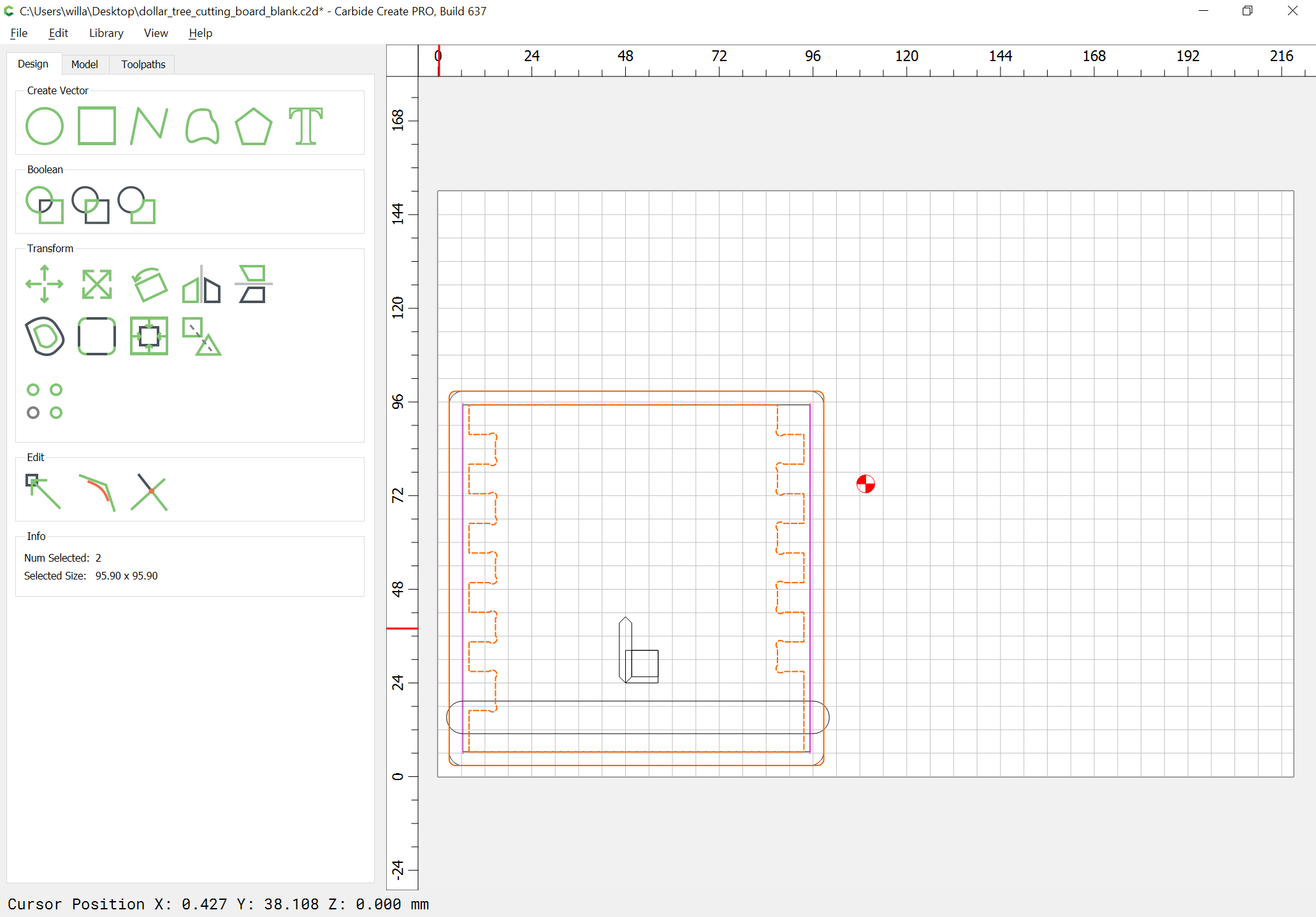
Duplicate the central geometry, drag it into alignment w/ the original and subtract the rabbet for the base from it:
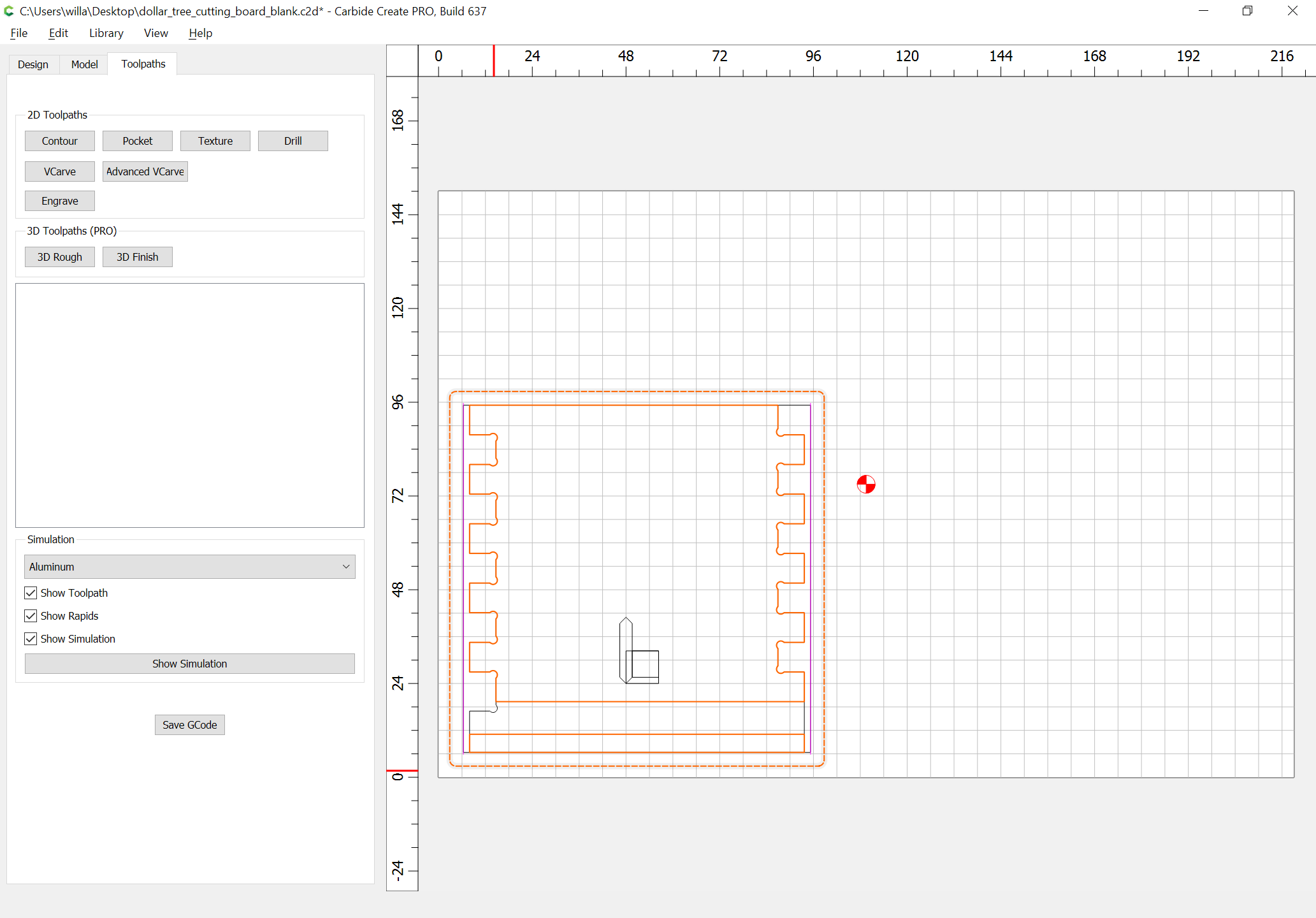
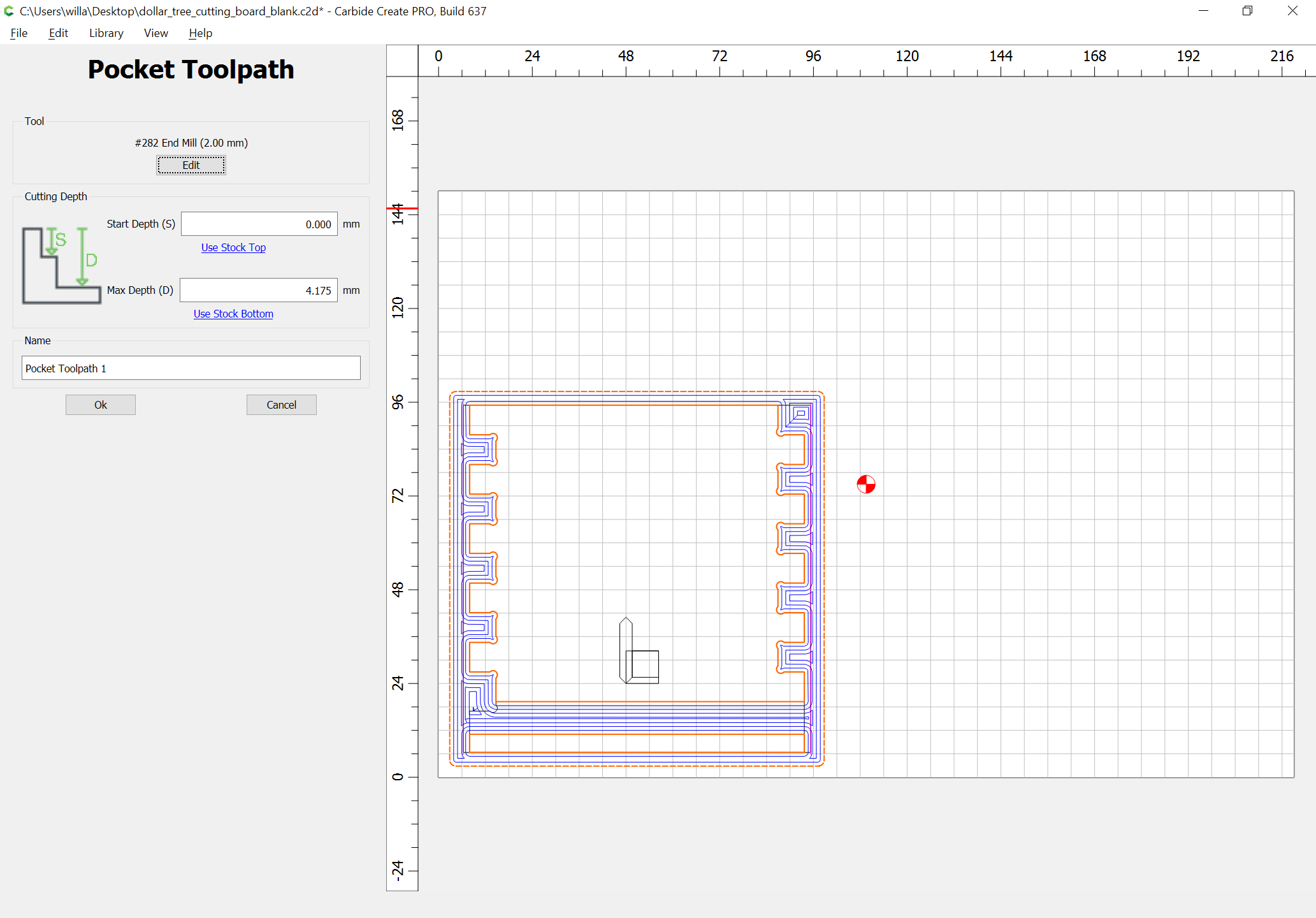
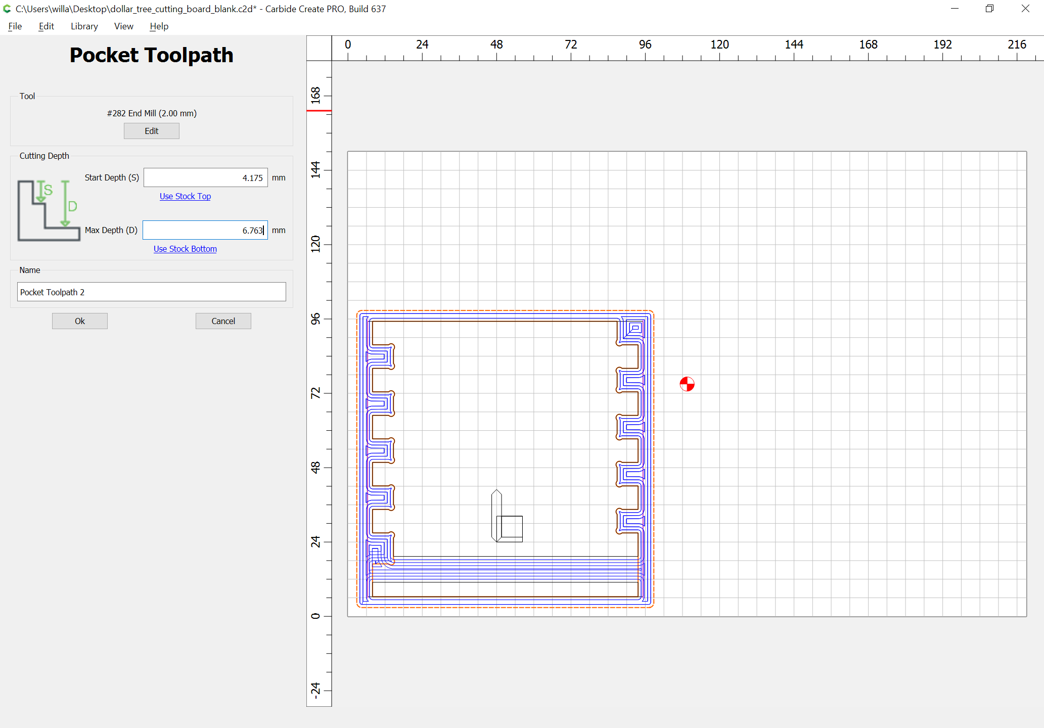
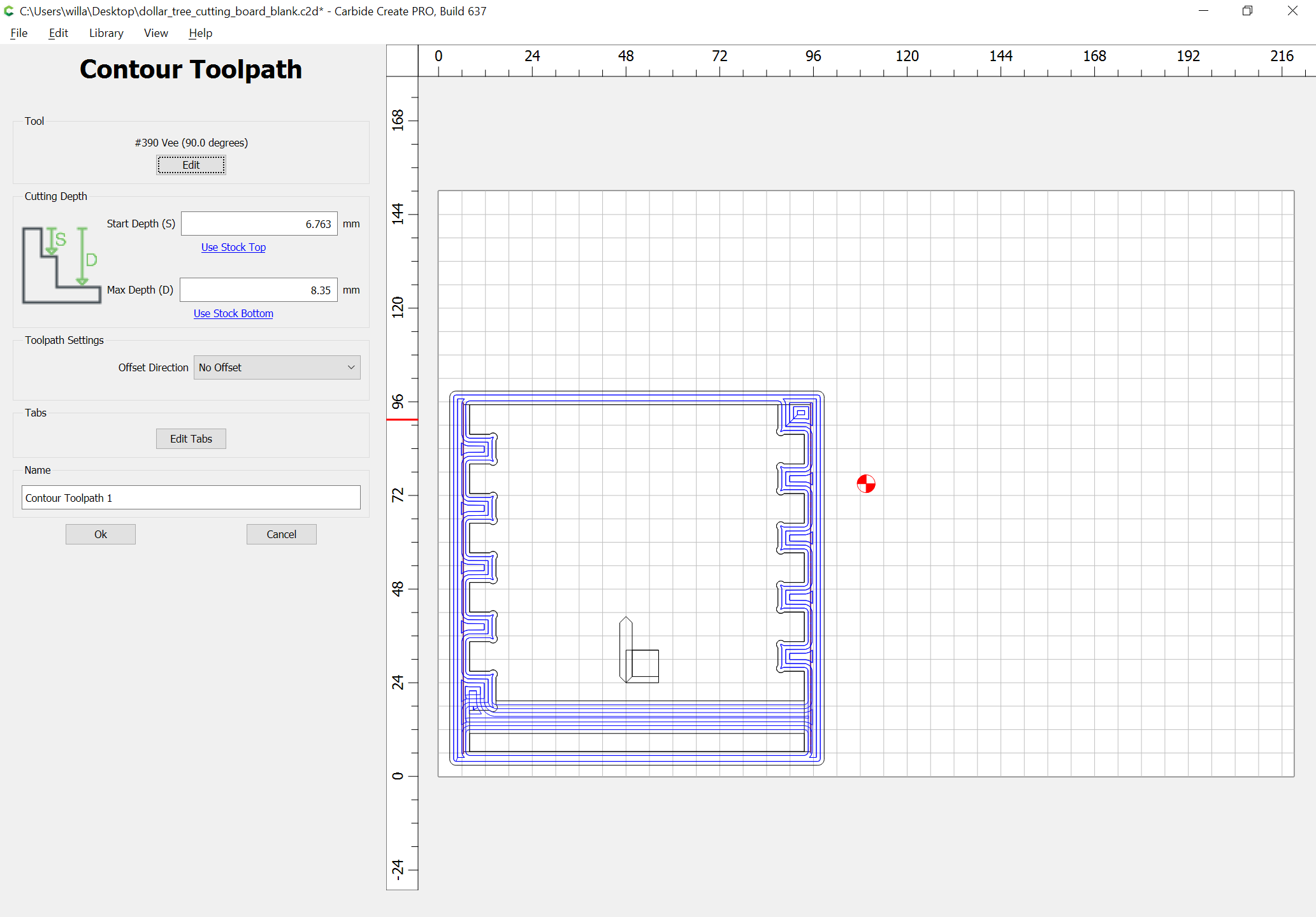
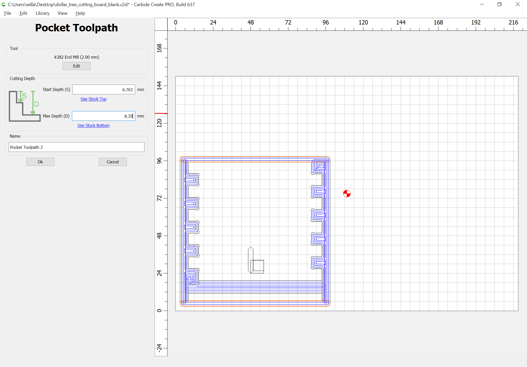
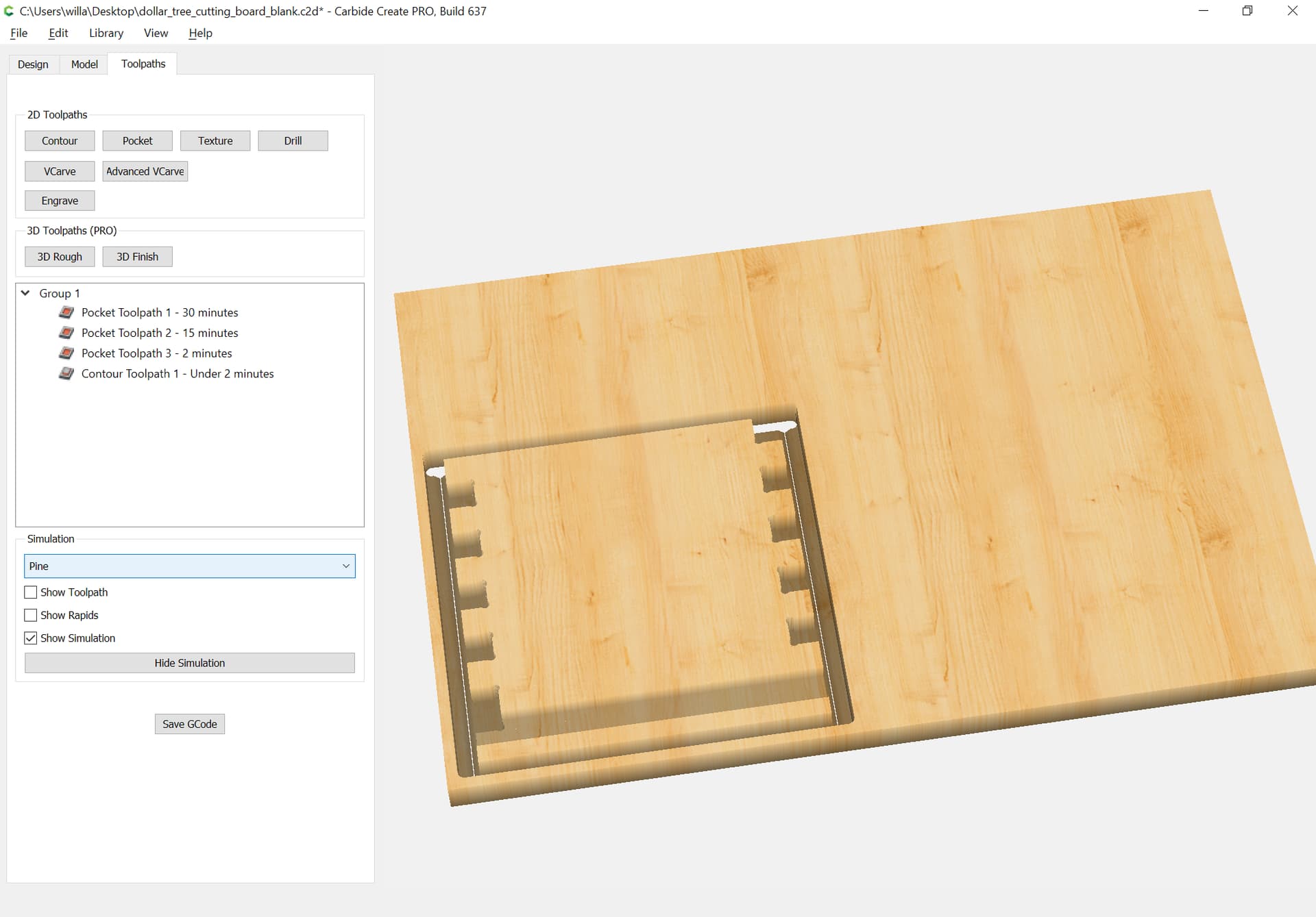
Then, it’s simply a matter of assigning toolpaths.