Ring around the donut?

So, I was doing an example prototype for a co-worker to show to a customer (my first “pro” job, whoo!), and… ran into something strange.

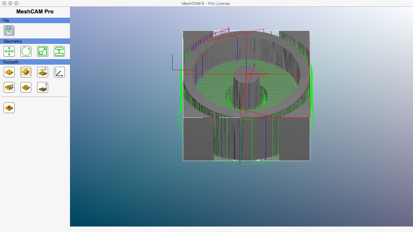
The model looks like this:

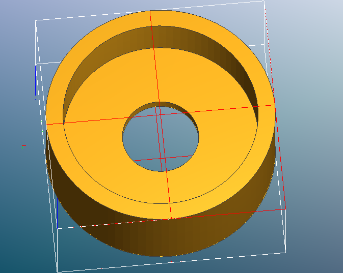
There’s some details on the bottom surface that make this a two-sided job, but I never got to that point.

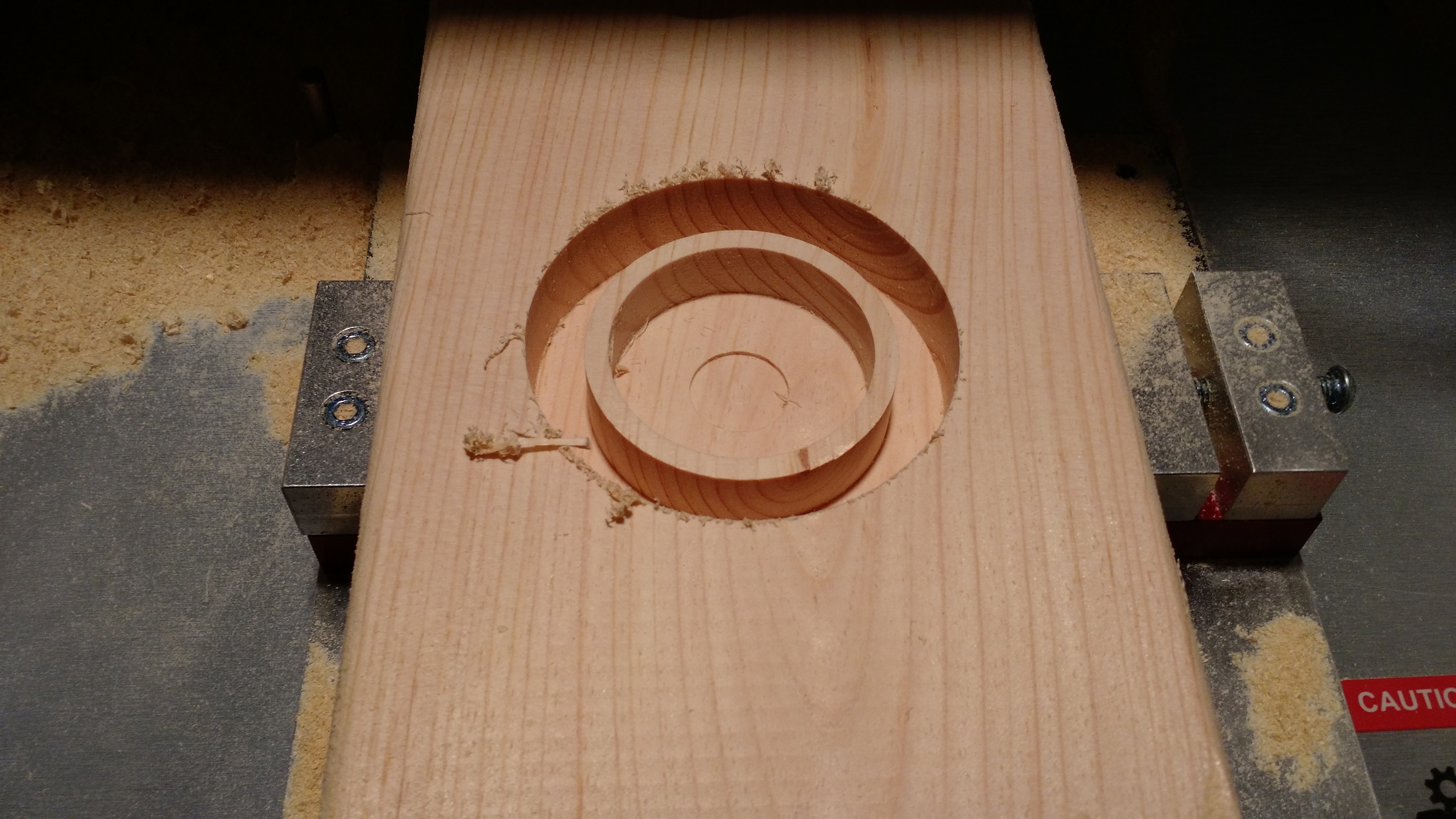
This is what the part looked like at the transition from the Roughing to Finishing phase:

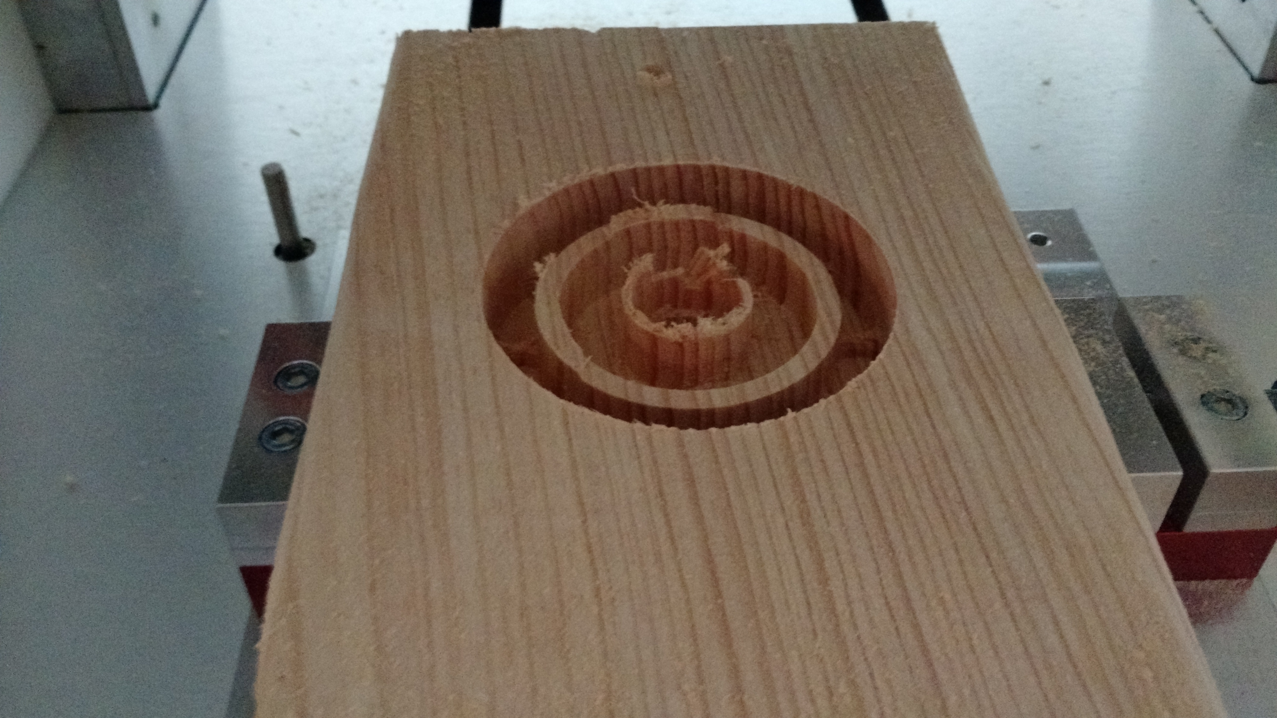
Since the shape was simple, I was running the entire cut with the .25" flat end mill, so there was no pause to change tools. But if you look closely, you can see that it was starting to do the Y-axis parallel-finishing phase. The cutter hit the center “donut” hard enough to stall the spindle and the axis motors. Going by my calipers, the “ring wall” is a little under .125" thick.

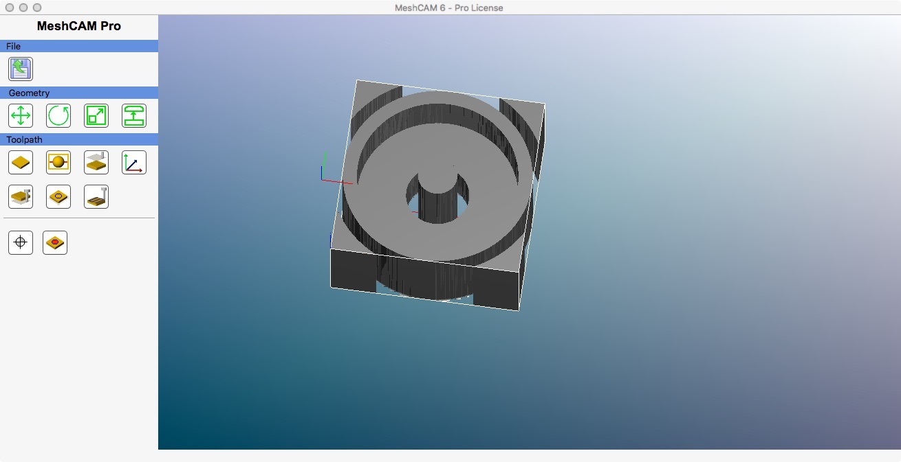
And, just to ice the cake, this happened to me twice. I re-generated the NC file from MeshCAM two different times, with slightly different feeds and speed, and both times this inner ring was left. And if I load the NC file into OpenSCAM, it also shows there (kind of – I’m not 100% on handling O-SCAM yet).

I don’t think it’s a problem with the original STL model, since I was able to 3D-print the same model without any issues (and actually “polished” it with the Nomad, but that’s a different thread).

So, it seems obvious that this ring must have something to do with the center hole at the bottom of the model. But I’m at a loss to understand why MeshCAM would produce a path that gets everything else right but leaves this ring during the roughing phase. The outer ring looks to be the right height and thickness, and every other part of the roughing phase looks to have completed perfectly well. But that inner ring is as high as the top of the stock – it’s like the NC path was avoiding it the whole time. And when the finishing pass started at the height of the outer ring… well, “crunch”.

So, my questions are: what did I do wrong here, and how can I keep it from happening again?
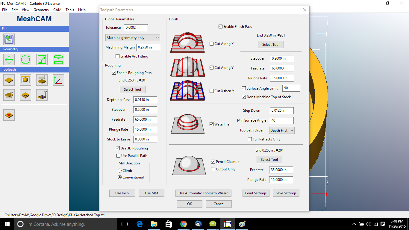
Settings:

Could you please post the STL file?

mark

Let’s see…

Notched Top.stl (328.9 KB)

Thanks! Digging now. It looks like you model is completely in negative Z. I have to some MeshCAM adjustment to get it aligned nicely.

Your STL model is very rough - emit finer triangles so it approximates a circle better.

BBIAB…

Program zero was set at the top, front-left corner of the stock, with the max depth set at about 55% of the model depth. The first time I did it, I did the other side first, and it worked okay, except that I bungled my Y zero after I flipped the stock and ended up off by the radius of the cutter. On that one, the “cup” side cut still left that inner ring, but thanks to the previous cut from the “flat” side, the anomalous stock ended up flaking away rather than stall the machine. But I saw it, which is why I did the “cup” side first on the second attempt, which is what the photo came from.

I just ran the job as a 3 axis job - no flipping - and things come out as expected for the “cup” side.

A parellel roughing would clear the center. Now to try it as a two sided job and see…

Two sided job, worked fine too. Here is the simulation output. I’m running the latest MeshCAM Pro for the Mac:

You can really see the roughness of the circular approximation of the outside this way.

Guest arriving so I can’t help more for a while.

mark

The rough STL wouldn’t surprise me – the source is an experienced mechanical designer, but STLs are alien to him (and, indeed, to our entire design department). Until he asked me to 3D-print some prototypes for him, he wasn’t even aware that his software would export STLs, or even what STLs were. I didn’t specify a mesh resolution to him, but since the files he gave me looked good in Cura, MeshCAM, and NetFabb, I didn’t think I would run into any problems.

And don’t worry, I’m amazed to be getting responses on Turkey Day. :smile: I was just posting to give my feet a break in between cleaning house before my guests arrived…

The supposedly circular shapes didn’t look good in MeshCAM to me. I spotted it first there and verified with my CAD program. :smiling_imp:

Could you please try it again, except with a Machining Margin of 0.251? Try with Parallel Path roughing.

Your finish speeds see to fast. If you can rough at those speeds, finishing should be much slower. I would finish at 15-20 IPM, plunge 5 IPM.

mark

Well, I had a chance to get back to it. Dropped my Roughing feed a little, and reduced the Roughing stepover from .2" to .15". Also checked “Enable Arc Fitting,” although I’m honestly not sure what that does. (Well, it sounded good… :stuck_out_tongue: )

And the results were definitely better:

I’m thinking that, between the softness of the wood, my aggressive feed rate, and the large stepover, I might simply have “shoved” the wood near the center instead of cutting it, leaving that ring. I wouldn’t have thought that leaving a wall that thick would be possible that way, but the evidence speaks for itself.

So much to learn…:persevere:

As a side note, that photo was taken without any vacuuming post-cut – the prop nut does an amazing job of clearing swarf away (well, wood swarf, I’ve yet to try metals), and the new dust-collection system sucks away the airborne stuff and keeps my lungs clear. I felt almost professional. :triumph:
(right up until I was doing the other side of the job and discovered the hard way that I’d forgotten to add geometry supports when I re-processed the job… :cold_sweat: )

NICELY DONE!

Also checked “Enable Arc Fitting,” although I’m honestly not sure what that does. (Well, it sounded good… :stuck_out_tongue:

This allows MeshCAM to convert circular shapes in circle drawing G codes (G02/G03). Alas, unless you’ve editing the post processor for the Nomad these things are disabled, even when the box is checked.

If MeshCAM can do it, and there are circular things to machine, checking the box results in significantly smaller G code files.

and the new dust-collection system sucks away the airborne stuff and keeps my lungs clear. I felt almost professional. :triumph:

Another safe air handler! :+1:

(right up until I was doing the other side of the job and discovered the hard way that I’d forgotten to add geometry supports when I re-processed the job… :cold_sweat: )

Funny how in the simulation it doesn’t go flying or damage a tool isn’t it? :smiling_imp:

mark