Router on/off and speed control with SuperPID and cncjs

I’ve been using SuperPID for manual speed control, but really want to take advantage of the gcode controlled on/off and speed control. This way I can walk away from cnc and have the spindle shut down automatically when it’s time for a tool change. There are some older posts on this with helpful, but outdated or incomplete material. Here’s how I implemented.

First, important to know my setup

  1. My controller board is 2.4e
  2. I’m using cncjs, I’m running the Windows Electron app most of the time (also have it on a Linux Mint machine)
  3. I’m using SuperPID for my speed controller

The Hardware - Shapeoko Controller 2.4e
Let’s start with the wiring. On the 2.4e board there are 4 empty holes in the top right that look to be labeled “SPID”. Interesting, right? These are even labeled with the 4 pins you need for controlling the SuperPID: GND - PWM - D13 - 5V. Make note of the “PROG” button, we’ll need that later.

EDIT: some 2.4e boards come with the header pins in place (lucky you if so!), see this post.

First step is soldering 4 pins to this SPID part of the board. (Side note, I’ve seen some other boards with mappings to the black 6 prong jack that is sticking out the front. I couldn’t validate that on this board, so went with what was labled.) To do this, you’ll need to pull the board from the controller box. Unfortunately, the heat sink is really glued on there, warm the back of the box with a heat gun or hair dryer to soften it up. I had to use a shim to start separating it, you can see I messed up the glue a little.

Not too stressed about that, plenty of contact with the back to dissipate heat, which must be minimal since it is a passive heat sink with no fan. Next I soldered on the pins. I picked up a bulk set of JST pins and a crimper for $30.

You’ll need a 4 strand wire that’s about 28g and long enough to reach from your controller to your SuperPID. I used an older USB cable (the newer ones, the wires are too fine to work with). Using a 4 pin female connector, crimp these wires in. Note that this style connector is easily reversed, there are not directional pins. I followed red as 5V and black as GND to keep it simple. For PWM and D13, just make a note when you’re ready to connect to your SuperPID.


The Hardware - SuperPID
This is the wiring from the controller and how you route to the SuperPID. The SuperPID instructions are well documented, but they don’t show this particular case, so I modified their diagram. Note that you must use the same ground as the controller, you cannot use power and ground from another source (like a USB plug) or the D13 pin and PWM pin will not work correctly.

Edit: Note that you must use the same ground as the controller, you cannot only use ground from another source (like a USB plug) or the D13 pin and PWM pin will not work correctly. I tried to use the +5V power source and ground from the controller, but it was not enough amps to power the SuperPID and fan, it was behaving erratically. Switched back to independent power source for SuperPID and fan and linked the ground wires to the Shapeoko controller. All works as expected now. Updated diagram:

My one issue with this setup is the 5V from the board would not power the small fan I have in the SuperPID box and turn on SuperPID. The fan is only 0.2A, so need to investigate that more. Edit: Gave up on this and went back to independent power source with a common ground.

Next up, I want to be able to flip back to manual mode, so I needed two switches. First, unsolder the jumper on the back of the board and attach three leads.

image

Connect the wires to a SPDT (single pole, double throw) switch in the same order. Middle wire on the board goes to middle wire on the switch.


This will allow you to switch between non-linear (knob) mode and linear (computer) mode. This is explained in detail on page 27 in the SuperPID manual. Next, I added a switch to go back and forth from manual speed control to computer speed control. This is different than the linear/non-linear - that is how SuperPID interprets the signal - this is where the signal is coming from - computer or knob. Using another SPDT switch, I wired exactly like the diagram on page 27:

image


I would have preferred this as one switch, a DPDT (double pole, double throw), but I had these on hand. Flipping both up goes to manual mode and I can use the knob to control speed. Both down and the computer is in charge, the knob does nothing.

Now were in business - power on your CNC and your SuperPID and you’ll discover… failure…

The signal from the router board turns on the spindle as soon as you start up. The D13 pin is reversed from what SuperPID is expecting.

Software - Update Shapeoko Controller
Ready to make some updates to the grbl on the controller board? There are three line changes you need to make. I was pretty nervous about this, but turned out to not be a big deal once I figured it out.

  1. First, head to this directory and download the latest Carbide Updater and grbl.hex file. This is your fail safe in case you make an oops and want to go back to the Carbide file

  2. Download Arduino IDE and install. (note - I had to download the beta version after Win10 updated last night, the stable version would not open).

  3. Go to GitHub - gnea/grbl: An open source, embedded, high performance g-code-parser and CNC milling controller written in optimized C that will run on a straight Arduino and click “Clone or Download” image and select “Download ZIP”. This downloads the latest version of grbl (for me, it was 1.1h)

  4. Unzip the directory

  5. Open “grbl-master” folder then “grbl” folder and you’ll see a file “config.h”. Right click and open with your favorite text editor (notepad, notepad++, etc.)

  6. Near the top, change:

#define DEFAULTS_GENERIC

Change to

#define DEFAULTS_SHAPEOKO_3

Then find these two lines and “uncomment” - delete the two // in front (credit to this site and this post for the code and explanations).

// #define INVERT_SPINDLE_ENABLE_PIN // Default disabled. Uncomment to enable.
// #define USE_SPINDLE_DIR_AS_ENABLE_PIN // Default disabled. Uncomment to enable.

becomes

#define INVERT_SPINDLE_ENABLE_PIN // Default disabled. Uncomment to enable.
#define USE_SPINDLE_DIR_AS_ENABLE_PIN // Default disabled. Uncomment to enable.

  1. Go to this post and download the config.h file @robgrz posted. This has all the Shapeoko modifications. Review your file and uncomment all the additional lines so it matches with the exception of the three modifications above and then save. (Why not just use this file from Rob and make the above change? My theory was the one I downloaded from grbl matched 1.1h, the one posted matched a different version). My version is here: config.h (49.2 KB). This may work for you, I matched the Shapeoko version and updated the three lines above. Remember, this was the 1.1h version, you can use it as a reference.

  2. Time to upload to your board! This is the most nerve wracking part for me, but it’s not hard. Go to the grbl compiler site and follow the directions EXACTLY using Arduino IDE. Every step is thoroughly documented, even if you are not a programmer, just read carefully and follow along every single line. The one piece not included - remember that “PROG” button on your board in the photo above? Now is the time to use it. In the last step, uploading the to board, press and hold the program button, then select “Upload” in Arduino IDE. When you get the message “upload complete”, release the button.

Software - Update with cncjs
Now for the last change - we need to tell the board the min and max RPM. In the links above, the older version of grbl has “#define SPINDLE_MAX_RPM” in the config.h file. I tried using those commands on this version and it didn’t work. Here’s what I discovered.

Open cncjs, power on your CNC, and connect. In the Console widget you’ll see a list of parameters:


Your parameter $30 is probably =1000. Scroll to the input > and enter

$30=30000

Hit enter to update the Maximum Spindle Speed. If the Minimum is not = 0, then update that as well. SuperPID is expecting a MIN = 0 and a MAX = 30000

$31=0

While you’re there, enable soft limits and enter the max travel for your machine. You’ll thank me when you don’t crash into the rails anymore when you’re jogging:


Those are my machines parameters, determine your max travel in mm and upate:

$20=1
$130=XXXX
$131=YYYY
$132=ZZZZ

And the test…
Are you ready for it? Here we go!

  • Flip your switches on SuperPID to Linear Mode and Computer Controlled
  • Power on your CNC and SuperPID
  • Power on your spindle mains to SuperPID
  • Connect with cncjs and home your machine
  • Go to the Spindle Widget
  • Enter 10000 RPM and click the M3 button (make sure your spindle is in a safe location)
  • In the Console Widget, you’ll see “M3 S10000” and your spindle turns on!
  • Back to the Spindle Widget, click M5, your spindle shuts down
  • Success!!
  • Go eat some tacos, it’s been a long day!

How to use this
Carbide Create automatically includes the M3 S##### and M5 commands. Now as you run your gcode, the spindle will start and stop automatically at tool changes and the start and end of your file. Also, the Feed/Speed/Rapid toggles will work while your job is running.

A few notes now that you’ve read all this.

I have not tested the CNC with Carbide Motion since I’ve made these changes. I exclusively use cncjs as my interface.

You’re taking apart your controller board and soldering it - probably not good from a warranty perspective. You break it… well, you already bought it. Don’t blame the nice folks at Carbide 3D or me. Same thing for flashing the new grbl. You probably won’t brick your board, but you could screw up some settings and make your router behave erratically. It’s your fault, not mine or Carbide’s.

You’re modifying and soldering on your SuperPID, same as above. The liability is on you.

These changes are detailed, but not hard. I’ve done my best to compile these instructions from multiple resources and annotate where the information came from to make it easier for you. These worked for me, with my setup, noted above. Your setup may be different and require different steps. Lucky you! When you figure it out, document it for others.

and finally…
Hope this helps you if you’ve been wondering how to implement but nervous to try since there aren’t any comprehensive resources. I know enough to be dangerous, by no means an expert. If you find something inaccurate or missing, please comment for others.

10 Likes

@dandangerous, this is a brilliant writeup, thank you for sharing!
The spindle+VFD users among us went through a subset of these steps to wire the PWM to their VFD, but having this tutorial available so that router+SuperPID users can also benefit from automatic start/stop is great.

I think the config.h that Rob posted a while ago matches the GRBL version in use in the Shapeoko firmware, which unless I am mistaken is version 1.1f. So when I recently rebuild/reflashed my firmware to add hardware feedhold support, I downloaded that 1.1f version and applied Rob’s patch as is.

2 Likes

Thanks Julien! I edited above to note that some of the 2.4e boards come with the pins already in place:

EDIT: some 2.4e boards come with the header pins in place (lucky you if so!), see this post.

And found your post on the ISP header for with the pin out for the 2.4d board, which is likely the same as the 2.4e.

I haven’t validated this, but looks like you can get to the same pins here without needing to pull your board and solder if your missing the pins at the top right. Interested to know if anyone has used these.

4 Likes

That header is where my prox switches take their 5V from.

2 Likes

@dandangerous Appreciate this guide you wrote up! Certainly helped with getting my CNCJS installation off the ground with the SuperPID…

One observation I have (which may well be how SuperPID is meant to work) is that the spindle won’t move in either ‘controller’ or ‘manual’ mode UNLESS an M3 command is sent from the Spindle Widget on the CNCJS webpage.

Once M3 is sent I can increase or decrease spindle speed from the GRBL widget. Or if I flick the ‘Controller/manual’ switch at the SuperPID Box - I can then enter knob mode and manually adjust the RPM by twisting the knob. (Again, this will only work after an ‘M3’ is sent from CNCJS).

I also note that the RPM inputted by me in CNCJS (and that which reflects back in the ‘Status Report’ of the GRBL widget) bears no relation to the RPM as shown on the LCD display of the SuperPID. I wonder why that is… See photo / screenshots below…

  1. SuperPID RPM pic…
  2. M3 Input RPM
    Screenshot 2020-06-30 at 22.19.55
  3. RPM Status Report
    Screenshot 2020-06-30 at 21.54.03

I thought SuperPID has a minimum RPM of 5000 no matter which way, software or knob.

Well, in manual mode you can go from 0 to at least 20,000 (I didn’t go further)… I set in CNCJS, the RPM limits as min 0 and max 30,000 as per the guide above.

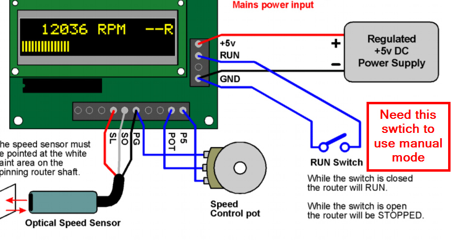
@michaelnewham check the wiring setup on your SuperPID. You should not have to send the M3 command in manual mode. You may not be showing your full control box, but looks like you are missing a few switches to change between computer and manual (specifically the manual run/stop, green switch in my photo). Here’s mine with a couple notes:


The min for SuperPID is 5000 RPM in either mode. Confirmed this in the pic above running manual mode and potentiometer set to min. In computer mode, any value below 5000 gets translated to 5000 because of how it interprets the PWM signal. Details on this are in the SuperPID manual.

Note, the computer/manual switch doesn’t like to be flipped once the SuperPID is on. It “boots” into that mode, so should be set to that prior to turning it on. Doesn’t seem to harm anything, but your pot knob won’t function the way you expect. If you change modes, power down SuperPID and turn back on.

2 Likes

I have a DPDT (double pole / double throw) switch whereby its either Linear/Computer OR NonLinear/Manual(Knob).

Will check the ‘start-up process’ I have again to see how it differs to yours.

Do you have the manual start/stop switch? Without that, you are correct - you’d need to issue the M3 command to turn on the router even if you are using the pot in manual mode.

I have a couple(!)…

  • I have one that Starts / Stops AC voltage getting to the Router. (under the SuperPID black box)
  • I have the original On/Off switch at the Makita Router itself which I left in. (Thought that was a good idea for when changing Endmills etc.)
  • I have the 5v enabled RUN from the Carbide 2.4d Controller wire connected to the SuperPID.

Basically if the Shapeoko is not turned on then the 5v signal to turn-on the SuperPID does not get sent and therefore the AC will not flow to the router.

So what I’m flummoxed with at the moment is why the RPM differs between CNCJS and the SuperPID display. The + and - 10% etc at the S setting on the GRBL widget works. (Will check if its actually 10%)

To truly use manual mode, without sending the M3 command, add the “Run” switch from page 19.

You can wire this in tandem with the controller feed.

Sorry, missed this - if you set cncjs to a value greater than 5000, does it respond correctly?

  • I will do that so. Handy to have ‘knob’ control if CNCJS is not providing correct RPM values.
  • No, I briefly checked there. I put in 7,500 RPM in CNCJS but the SuperPID showed about 21,500.

Pictured below is the GRBL readout from the controller after connecting over serial via CNCJS…

I’m only basing this on your original picture:

image

Those three things tell me:

K = SuperPID is in Knob mode
O = SuperPID is in Override mode (ignores light sensor)
R = SuperPID is telling the router to Run

To be in Computer mode (which would set the curve to be linear) you would want to see three dashes there when you power on and just the R when you are running.

This is the “O” meaning you have OP and TG shorted overriding SuperPID (Page 27 of manual) - disconnect this so it is a “-” when you power on SuperPID.

This is the “K” meaning you are in Knob mode not Computer mode. Change your wiring so this is a “-” when your pot is disconnected. This will put you in linear mode.


Your switch should be

  • Knob mode (non-linear) & Pot connected = “K”
  • Computer mode (linear) & Pot disconnected = “-”

This is what is should look like when you power on SuperPID in computer (linear) mode.

Try flipping to that setup and then sending the rpm settings from cncjs and tell me what happens!

3 Likes

Fantastic @dandangerous!

I removed the shorting wire between OpPand TG terminals - after that things seem to be going well…

Some observations…

a) Spindle will not run unless M3 is sent from CNCJS (fine with me)
b) In ‘Computer/Linear’ mode, actual SuperPID RPM is about 100 - 130 more than that inputted via M3… up to about the 7,500 RPM range which I checked. (fine with me I suppose).
c) Booting ‘into’ ‘Computer/Linear’ mode seems to have more ‘functionality’ than booting into Knob/Non-linear mode. In Computer mode, I can flick the switch to allow me to adjust RPM on the Knob. Flicking back then returns to the RPM as provided by the last M3 command via CNCJS
d) CNCJS does not get feedback from SuperPID as to actual RPM at the spindle (therefore having the spindle ‘status’ displayed on the CNCJS GRBL widget is redundant with SuperPID).

Again, thanks for all the help…

Now to focus on an external vacuum set-up !!

1 Like

Nice! Glad it’s working closer to expected!

Adding the manual Run switch will allow you turn on the router without the M3 command. Note that if you turn it on with the M3 command, this switch will not turn off the router.

SuperPID takes a voltage value and translates it to the rpm speed. This is simplified a little, but if you have a range of 0-30,000, then you have an increment of 300 rpm units for each 1% change in the PWM wave. The PWM wave gets translated to a voltage value for SuperPID to create the final rpm value. So, correct - the exact value displayed on SuperPID will be slightly different than the value you enter in to your gcode because there are only X# of steps for it to interpret. I think it’s a little more granular than 1% steps, but can’t find the documentation right off. See Page 22 in the SuperPID manual:

Correct, when you flip the switch, you’re essentially cutting off the signal from the PWM and switching to the pot. Keep in mind, you booted to computer mode, so the knob will be linear making it a little harder to control finely. Flipping back cuts the pot and revives the PWM signal (which your controller was sending the whole time, but you blocked through the switch). This is true regardless of which mode you boot into, SuperPID doesn’t care where the signal comes from. Which mode you boot into only determines whether the speed curve is linear or non-linear, which changes how either input source behaves as SuperPID interprets it.

Yep - one way only, there’s no communication back to “error check” the speed on the controller board or back to cncjs. Having it in both places is not redundant, IMO. The one in cncjs is telling you what the output is - what message is being sent to the controller. The SuperPID display tells you how it is interpreting that signal and give you live feedback (is the router bogging down and losing rpm, need to decrease feed rate, etc.).

While you’re in there, here’s a post on setting up some custom commands for rapid positioning:

This was a fun one to troubleshoot - I had never used the OP override before, learned something new! :slight_smile:

2 Likes

This topic was automatically closed after 30 days. New replies are no longer allowed.