When I design my projects in CAD software, I tend to layout my projects with the X,Y origin in the center of the stock, and not the lower left corner. Because of this, I can’t use the Touch Probe to find my work zero. Instead, I use a laser with a crosshairs pattern.
My approach is to semi-permanently attach the laser a fixed offset from the endmill center. On any new job, I turn on the laser, jog my machine until the laser crosshairs are over the center of my stock, and then run a macro to set the coordinates of the end mill to the laser offset.
To determine the offset:
- I zeroed my work coordinates
- I used a v-bit to cut a plus-pattern in some scrap wood, centered at X0 Y0
- then I jogged the laser over the cut and noted the X and Y offset (for the example below, lets say the offsets are 39.997mm and 43.234mm)
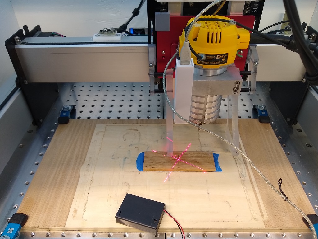
In the image above, you can see that the laser is aligned over the plus-pattern cut into the scrap stock (this could easily just be a pencil mark on new stock). After aligning the laser, I execute the following g-code to set the cutter’s position:
G21 ;mm mode
G91 ;relative motion
G10L20X39.997Y43.234 ;set Work X to 39.997mm and Work Y to 43.234mm
G90 ;absolute mode
Note that I use bCNC as my CAM software, so I have a custom macro set with the g-code above so that it is all done with the press of one button. After executing the g-code, if I now go to my X0Y0 position, the end mill will be right over the plus-pattern.
I realize that this may not be as accurate (to the thousandths) as a Touch Probe, but for a solution that allows me to locate X0 and Y0 anywhere on a piece of stock (any of the 4 edges or the center), it has worked a treat for me.
If anyone is interested in the construction details, my parts list is:
- Laser with crosshairs pattern
- Battery pack with built in on/off switch
- USB extension cable (I had lying around)
- 3D printed case
- M5 screw
- 4 #6 screws to secure the cover of the 3D printed case
I designed the case and 3D printed it to hold the laser on one end and the female USB connector on the other. I also had flanges come out the back to hold it vertically on the router mount.
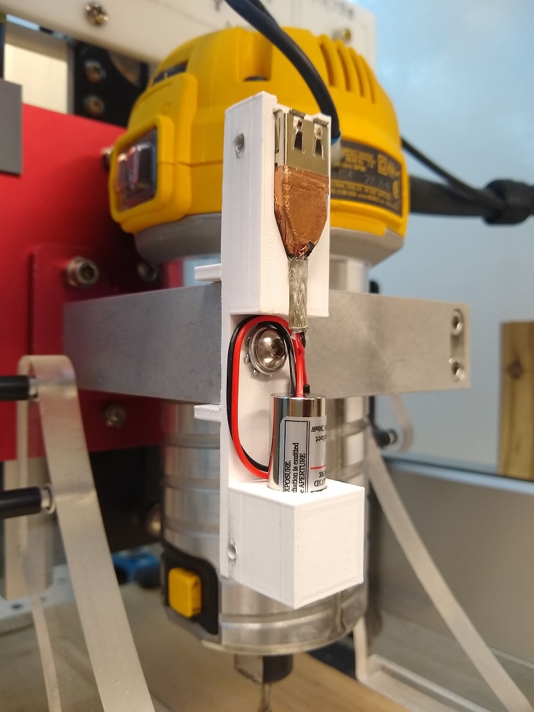
I then drilled a hole in my Shapeoko mount and threaded it for an M5 machine screw. This is how I semi-permanently mount it so that it doesn’t move and change its offset (I mounted it way to the left to make room for my dust shoe). The laser runs off of 3-5VDC, so I just used the Power and Ground lines from the USB cable extension to drive it. The other portion of the split extension cable is connected to the battery pack’s power and ground. This allows me to connect the battery pack to align my bit, and then disconnect it and move it out of the way when actually milling my piece.
{I got this original idea from a post on Thingiverse, but this is my take on the idea.}
