Ah, right, I forgot about that, sorry.
Do you know where the limit switches connected on that gShield ?
1 Like
Answering my own question, it seems like on the Arduino+gShield the limit switches were connected to pin 9,10,11 of the Arduino,
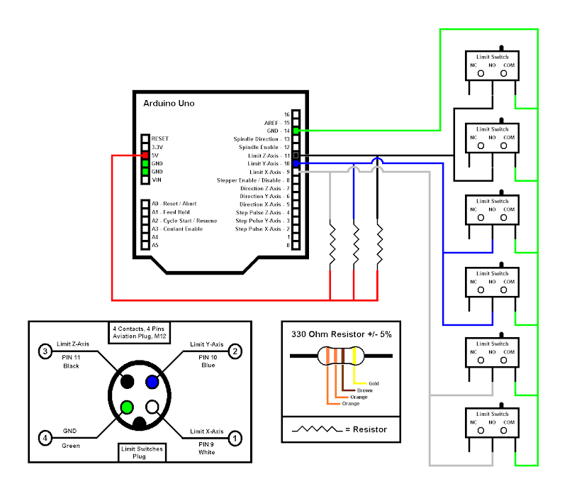
So I’m a bit mystified because the controller picture above does not seem to have any wire coming anywhere near pins 9,10,11. @josephkerr just so I know, where do the limit switches wires go on your machine?
1 Like
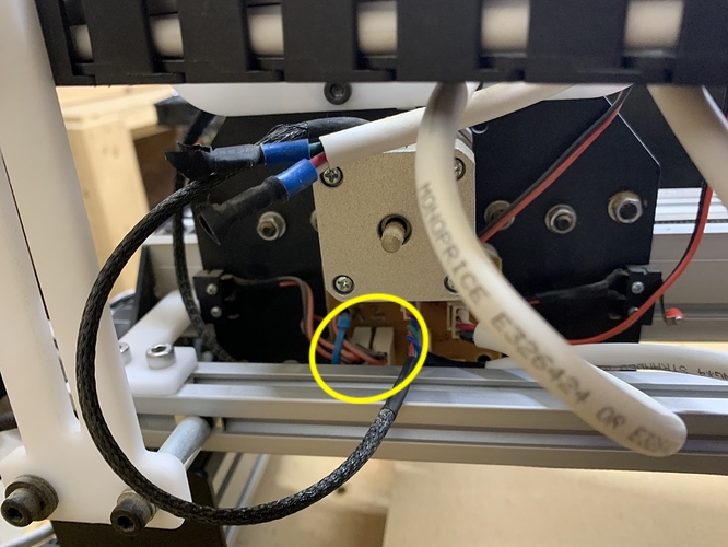
I’m right there with you Julien. I was looking at a wiring diagram like this today and I was winding this exact same thing. I did not build this machine. My friend bought the machine already built, and I’m helping him with this upgrade. And I can’t seem to figure out why the limit switch are not working but I’m really starting to think it has something to do with the wiring. I’m not 100% sure on where they could be from the Arduino+gShield. I’ll see if I can get a video to post in here showing the wires. Here are some pick of some of the wiring. The black and red cords are for the limit switches.
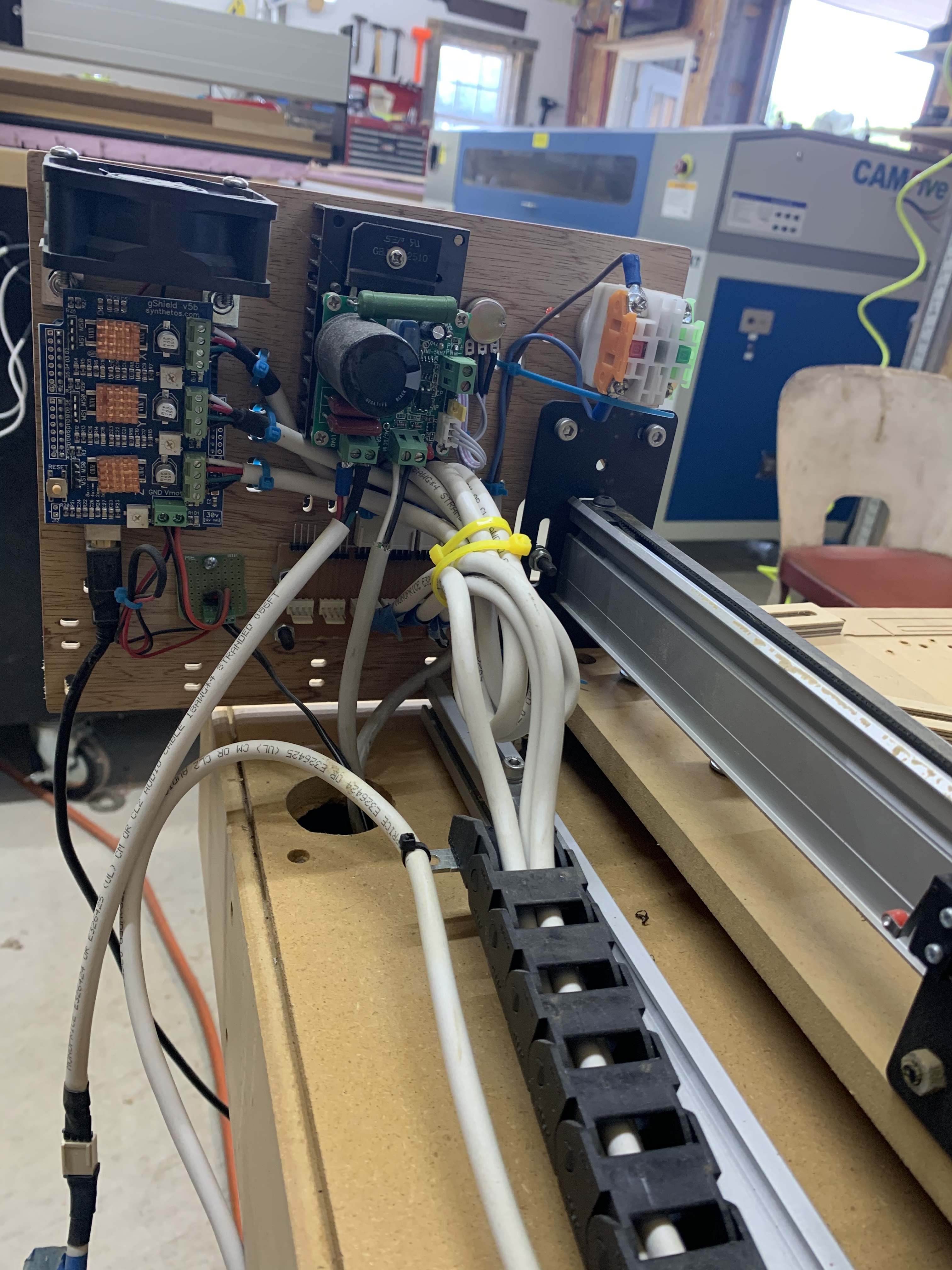
Do those connect to the controller anywhere? I don’t see the wires going back to the gshield.
1 Like
Me neither, and there are so many things going on in this setup that it’s hard to tell.
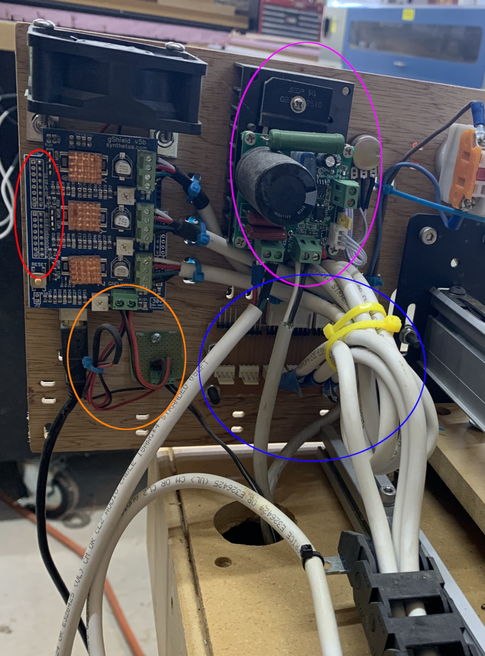
Red: this is where pins 9,10,11 of the Arduino are, so I would expect limit switches wiring to end up there, but nope.
Orange: that’s the power supply, which explains the red and black wire also visible on top of the gShield, it powers the fan. Nothing to see there
Purple: I wonder whether this is something for RPM control of the spindle ? There is a potentiometer there that I guess is used from the other side of that panel, and some big *** thermal sink, so it must be that.
Blue: well it’s impossible to tell from the pic what is going on in that area, but it would be interesting to check if the limit switches wiring end up there ?
- I would try and pick ONE limit switch, and trace its path/wiring from the switch to…wherever it goes, to understand where it ends up being connected. The way it stands, I don’t understand how it can work, but there may be a trick.
- If this turns out to be too difficult to troubleshoot, maybe an alternative path to a working solution would be to…forget about limit switches altogether, forget homing, reset $22 to 0, $21 to 0, and in LightBurn after powering up the machine just type “$X” to unlock the machine movements. I’ll test this procedure with LightBurn tomorrow when I get a minute, but it should work.
2 Likes
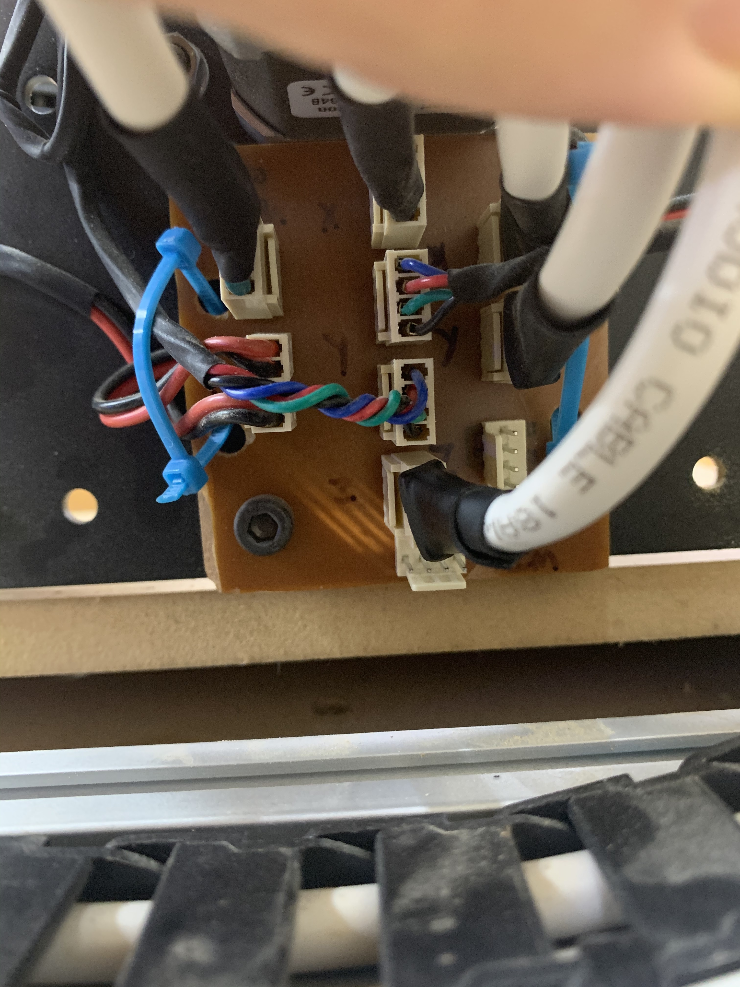
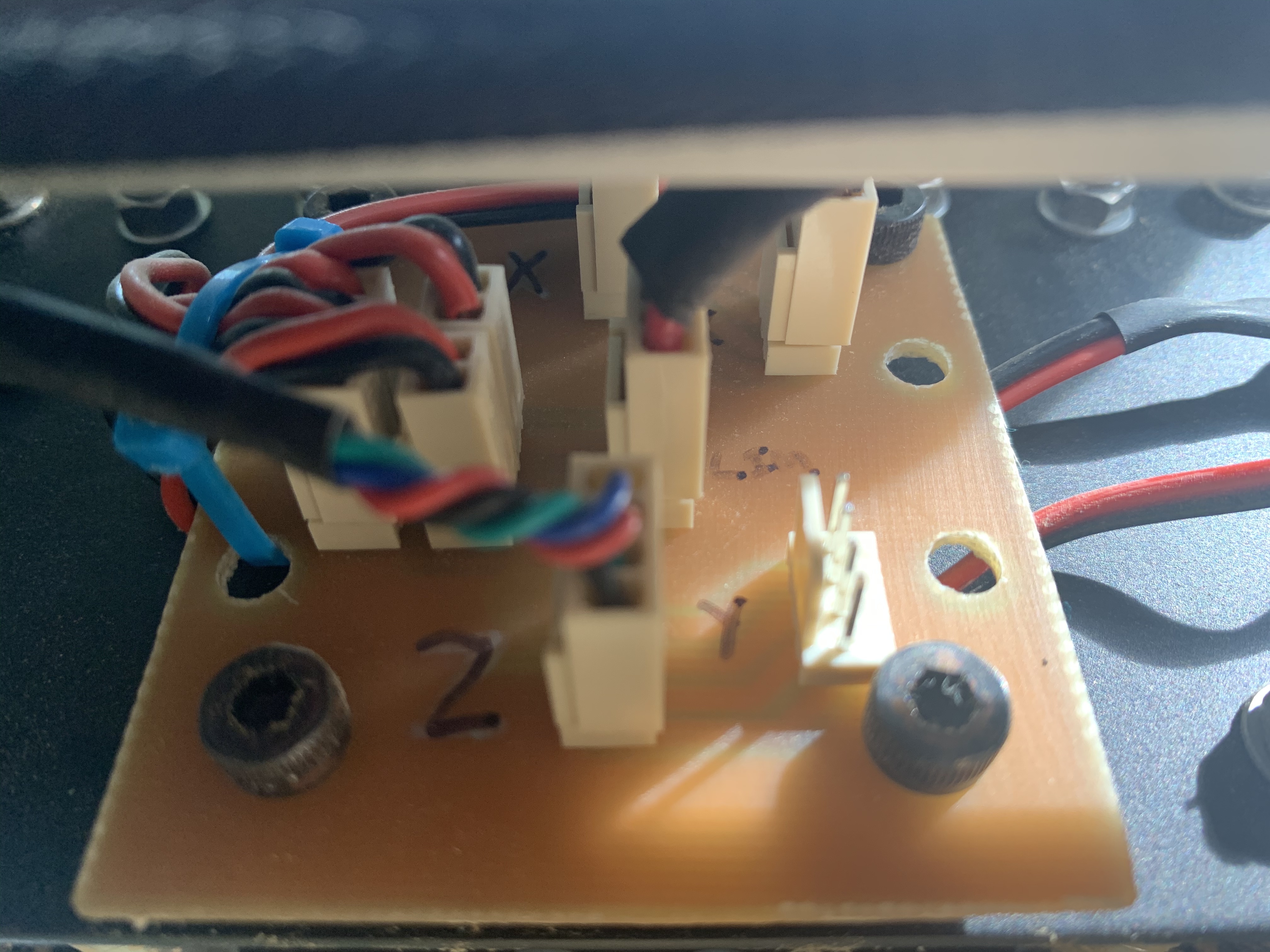
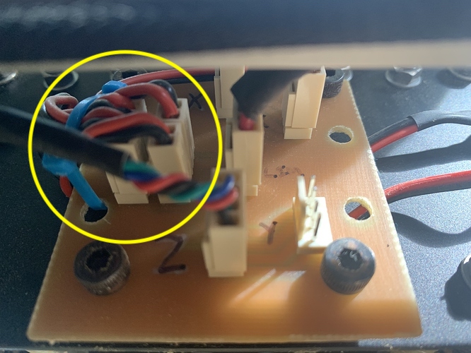
So the black and red cords coming off the limit switches don’t run directly back to the Arduino and gShield. The ones for the Y axis plug into what looks to be relay board an the ones to the X axis plug into a different relay board and I can’t seem to find any wires for the limit switches that run back to the Arduino and gShield. No sure if the guy who built this wired this differently or was running the machine with no limit switches. The first picture is the Y and the second is the X. When I get back to the machine I’ll try $X to unlock the machine movements and see what happens.
No, not that I can find and that’a why I’m thinking this is wiring issue.
Yeah it’s hard to figure out what’s going on with these custom boards, it may have been wired to leverage limit switches at one point, or may never have been completed. Anyway unless you feel comfortable disassembling everything to troubleshoot I would just ignore that and consider that for now your machine has no limit switches (i.e. call it a project for another day/year). It’s not such a big deal, the only drawback really is to not be able to reposition the machine automatically when it has been powered off, but for lasering jobs, manually realigning to a know feature on the piece/wasteboard will probably be more than precise enough.
In the meantime, I actually tried the procedure I recommended earlier, and it works (in my setup):
- power on the Shapeoko
- launch LightBurn
- LB autoconnects to the Shapeoko, as seen in the console
- type $X to unlock
- jogging using LB’s job buttons then works.
- “Set Origin” button allows to define the zero.
- loading a design, selecting “User Origin” in the “Start From:” option, and pressing the “Frame” button moves the gantry in a box around the design as expected.
1 Like
Ok, move on from the limit switched for now and I’ll do this on Saturday when I’m back at the shop. Thank you for all you help I’ll let you know what happens.
1 Like
This topic was automatically closed 30 days after the last reply. New replies are no longer allowed.