Shapeoko 3 XXL Initial Setup Tips

I decided to post my findings as a first timer building / setup of a CNC Router. The Shapeoko 3 XXL.

In my opinion, the online assembly guide could be better written. On the other hand, that can be subjective depending on one’s skill set.

The topics are Not in any particular order. I will post pics along the way.

I have come to this conclusion only after I got to Step 9, Squaring. I now have my entire Shapeoko semi disassembled so that I can check each of the carriages sub assembly individually and not the entire gantry.

So why did I come to disassembled my rails / carriages assembly? I could not locate the source of the bumpy feeling and bumpy noise as I pushed the gantry to the front and to the rear during the squaring on step 9. Also, with the belt attached, it required additional effort to move the gantry thus I could not determine if there were any binding. The objective was to achieve a free movement with no bumps.

I would deviate from the online assembly instructions steps and …

  1. do not install the carriages.
  2. do not install the belt.
  3. do not install the wires.
  4. adjust the V-wheel eccentric nuts to ensure a loose fit when installed on the rails.

… until completion of the “squaring step”. Also, I would check and adjust each V-wheel for a smooth feelings with no bumps along the rails.

1 Like

I would CAUTION not to install any of the carriages onto the rails without adjusting the eccentric nuts to the furthest position.

The factory has preset the V-wheels to fit the rails, but in my case they were excessively tight that it destroyed the bearings in the V-wheels. I am still going over each V-wheel to find which V-wheel is causing my bumpy issues. It’s a tedious tasks and so far on one carriage I found a notchy V-wheel and a V-wheel with a flat spot on the v-groove.

The tasks of working on adjusting 1 carriage at a time is a lot simplier then an entire gantry.

Here’s how I went about checking the V-wheels to find the bad V-wheel.

Support the X rail and Y rail. Remove the 4 screws on the X rail and Y rail.

Note how easier this would have been without the wires or belt. Hence why I would bypass this step.

Checking the V-wheel for a notchy bearing.

Rotate the V-wheels. It should be smooth with no bump or notchy feeling.

Eccentric Nut Initial Setting

It is recommended to set the eccentric nuts before placing the carriage on the rails

Set the eccentric nut such that the eccentric nut position the V-wheel futher apart (Y right/left or X axis) or closer together (Z axis). The objective is to obtain a loose fit when the carriage is on the rails.

Placed the carriage on the rail with the top V-wheels resting on the rail’s V-guide.

Install the both lower V-wheels. It is important that the flat washer is between the V-wheel bearing and the carriage plate. The purpose for the flat washer is to compress only on the inner bearing wall and not the outer bearing wall. Hence the hex bolt head compressing on the inner bearing wall.

Verify that both lower V-wheels are position on the bottom rail’s V-guide.

Snug the hex bolt but do not tighten.

I bought a used xxl and went through the Z carriage today. There was considerable sawdust buildup on the v wheels and the rails. I cleaned the rails with mineral spirits and the white 3M non-woven sanding sponge. I had ordered a xxl maintenance kit and two of the v-wheels has some chatter marks on them so I replaced them. Some of the v-wheels had 5mm washers and some did not so I went to Ace Hardware and bought 10 5MM washers. I replaced all of the washers to make sure they were all the same thickness and saved the originals. I made one mistake by installing a washer on the idler pully and installed it backwards. I moved the z carriage and the belt kept coming off. I realized the mistake and re-installed the idler in the proper orientation. Since I was working on the z carriage I replaced the belt and saved the old one. Because I installed a washer behind the idler the carriage would not go all the way home and activate the switch. There was just not enough room for the bolt that holds the idler to hit another bolt head. I removed the washer and the carriage was perfect. The main reason to disassemble the z carriage was when tramming I was getting slight groves on the Y axis and I shimmed the bottom of the router mount with two layers of heavy duty Reynolds aluminum foil. I re-trammed the spoil board and got the same groves but in the X axis this time. I have a 123 setup block coming tomorrow and will reset the router mount and try tramming again. I made 3 new spoil boards from plans on youtube from Myers Woodshop. The new spoil board have 2x2 inch spacing for 1/4-20 5/16" Tee nuts. The spoil boards should work well. The plans include fences for the front and left sides as well as L stops and cam clamps. I have a Shard Pro Plus HD and made the spoil board with T-slots and 1/4-20 Tee Nuts. The T-slots are not practical because the MDF distorts when tightening 5/16" T bolts and are unusable with 1/4-20 bolts. I will make a new spoil board for the Shark using the same principles used by Myers Woodshop. The new spoil boards are machines and ready to go as one wears out. I bought a whiteside 6210 1" 3 wing cutter to tram the spoil boards. I emailed Whiteside about the feeds and speeds and they recommended 100 IPM and 15000 RPM. I set the IPM at 80 IPM and set the router on 4 (Dewalt 611). The Whiteside that I added to the bit library set the speed at 4 IPM and it took 4 hours to complete the first Tram. I changed the speed in the file and recreated the gcode. The second tram took 20 minutes to cut a 32x32" spoil board. That was a considerable difference in speed. After I get the router squared I will tram one more time. I did have a low spot on the front left corner and one more tram should get the spoil board flat.

This is a 2 part adjustment of the V-wheel. I am not sure if this is the correct way since I have no experience with this CNC machine. However, this is how I am attempting to adjust the V-wheel.

1) Go-Nogo adjustment.

2) V-wheel slippage and out of round check (flat spot).

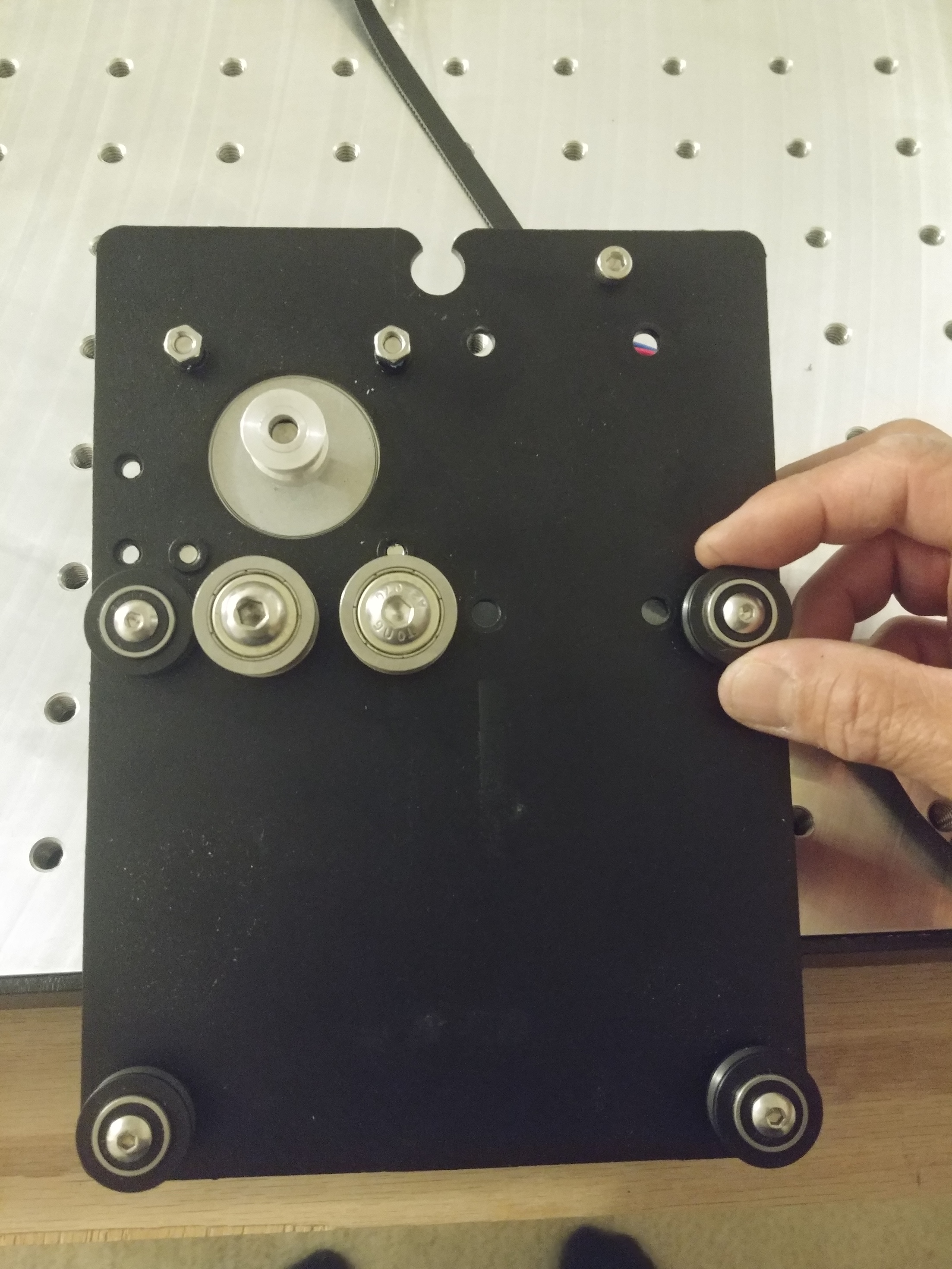
Since the V-wheels come installed from the factory, this would be a good time to check the V-wheels bearings. Rotate each V-wheels and check for smoothness. It should feel smooth and not notchy. Rotate back and forth, clockwise, counter clockwise … the objective is to feel that bearing for smoothness. So far, I found one bad notchy bearing.

The resulting cause of the notchy feel is that there are 2 bearings that are not seated parallel to each other. Under compression of the hex button bolt, this out of alignment causes the notchy feeling. Under no compression it goes undetected. So check ALL V-wheels under compression.
.
.
.
.
Go- Nogo

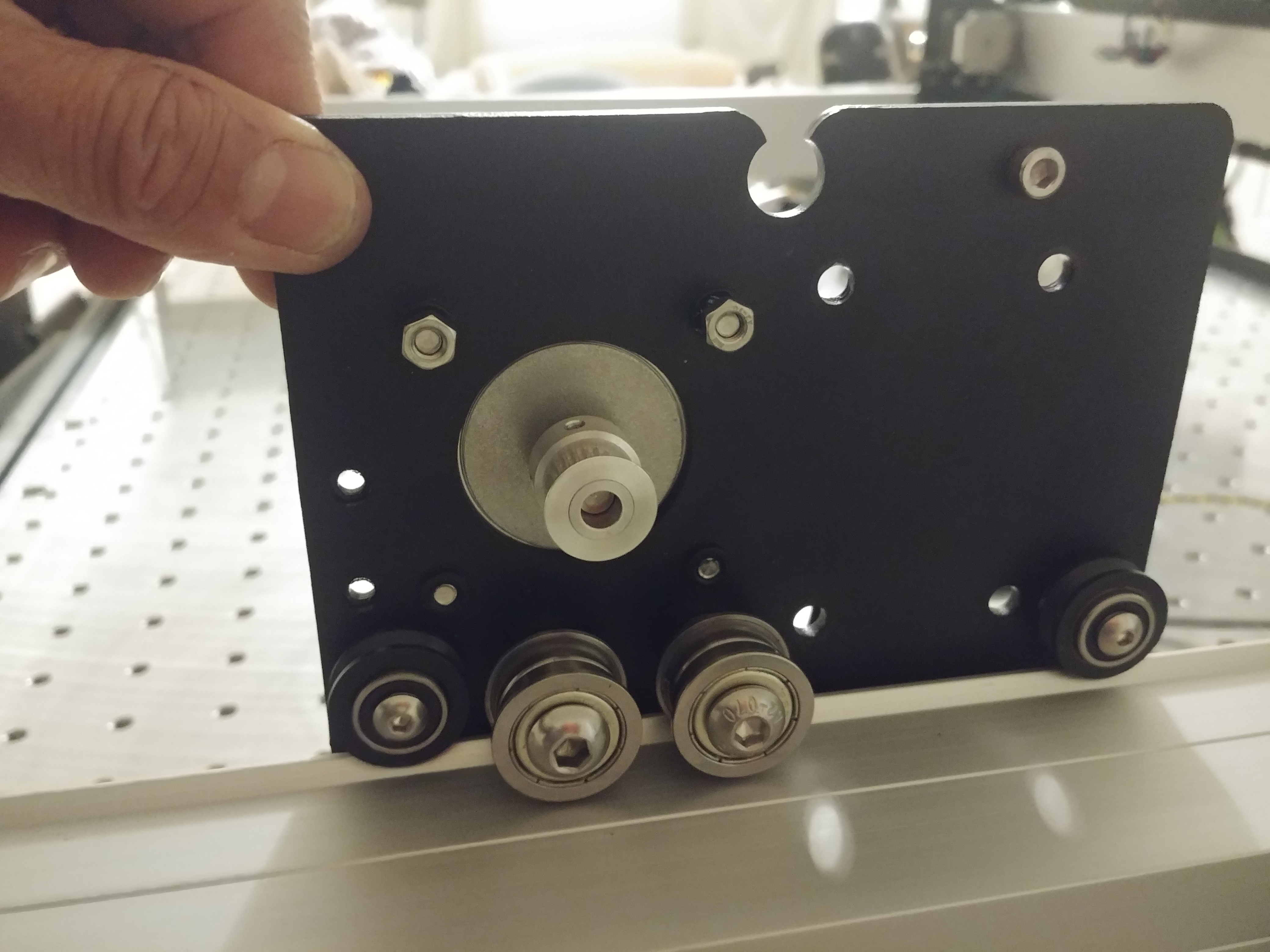
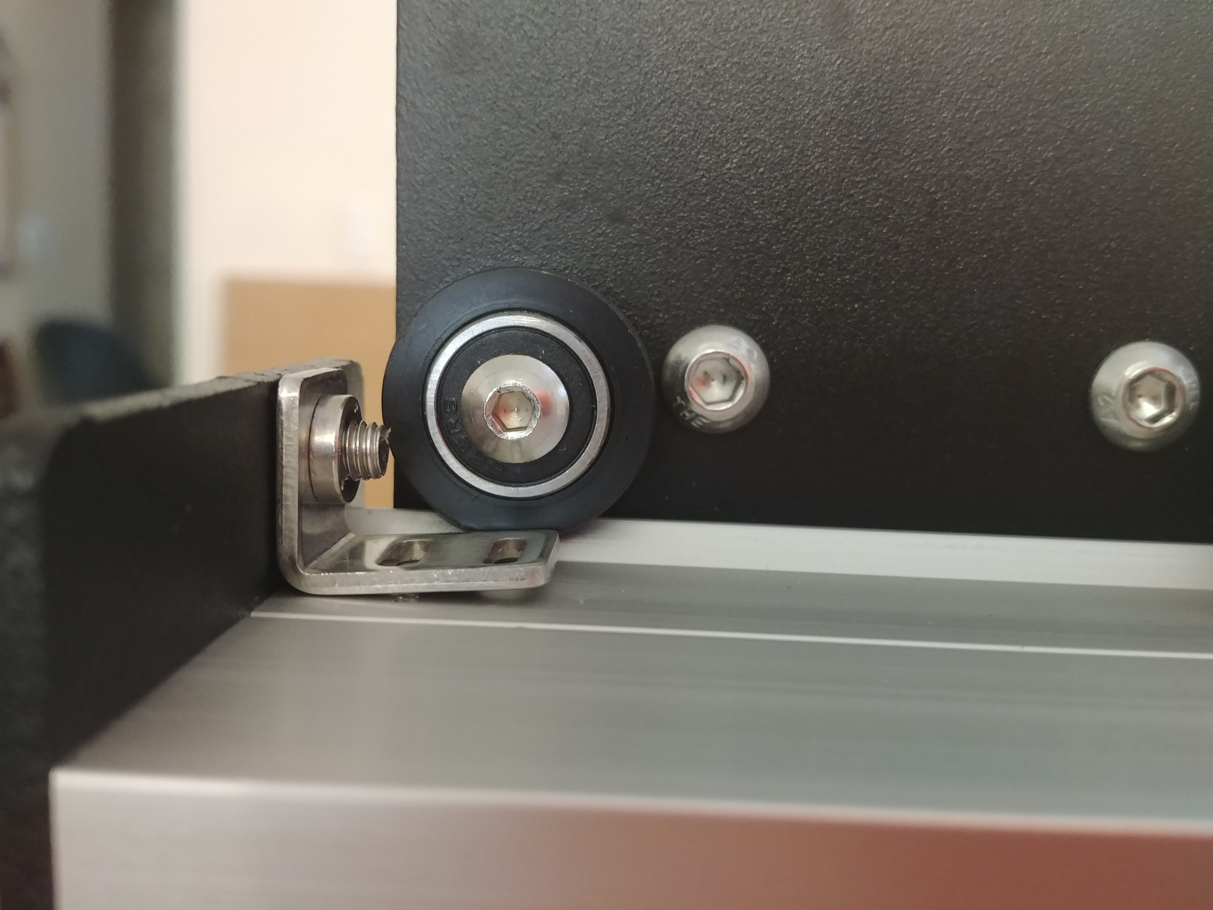
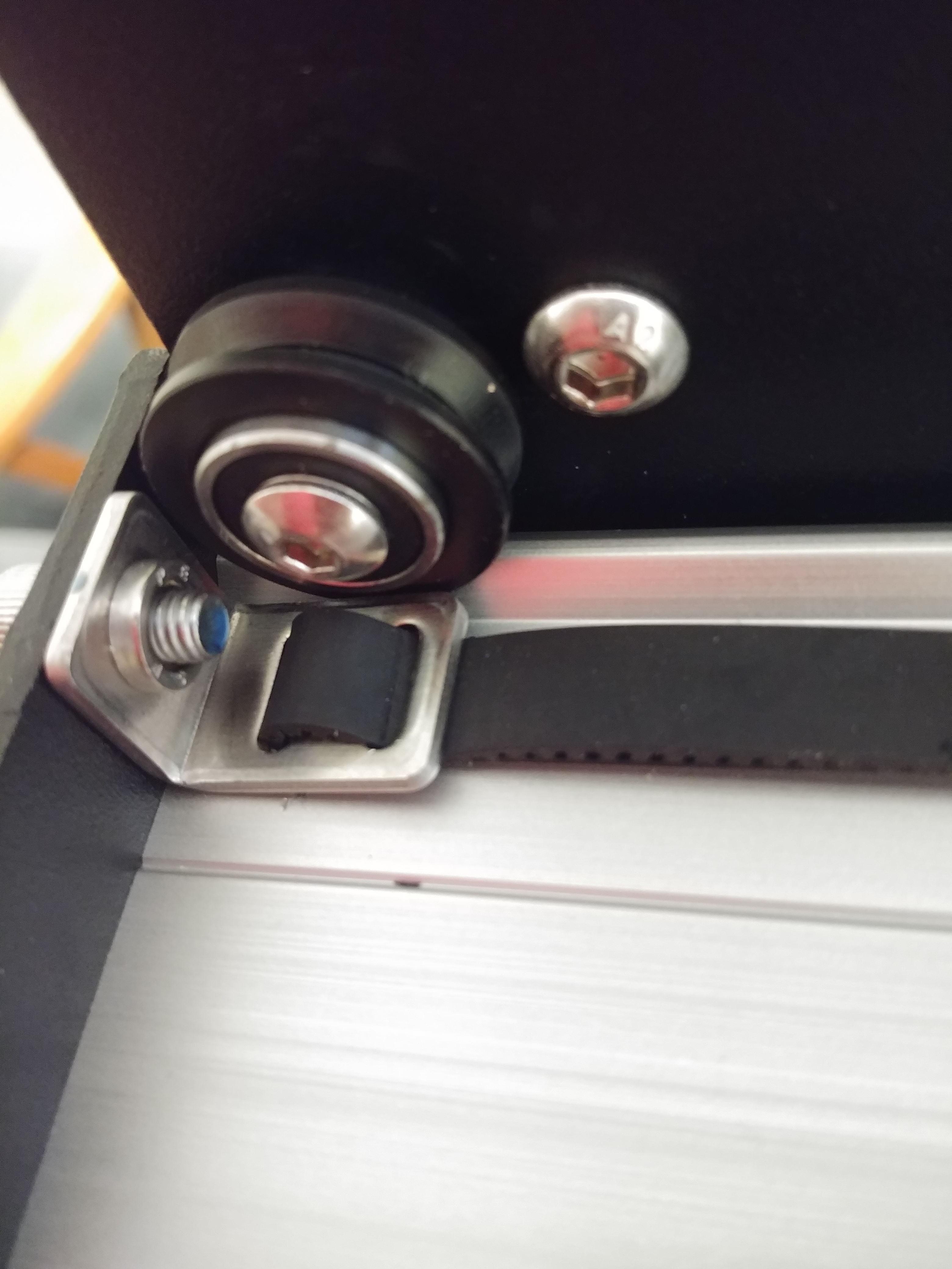
Lift up on either corner of the carriage and take note of the up and down play.

Adjust the eccentric nut “Equally” and in small increments such that there is no up and down play.

With both hands on each upper corners of the carriage plate, moving in opposite up and down direction, feel for any play. The objective is to creep up in adjustment by rotating the eccentric nut thus removing any play.

The pix only shows me using one hand. That’s because my other hand is taking the pix. Using both hands in on opposite corners/ends give you the added leverage as you rock the carriage up and down feeling for that minute amount of play.

ALWAYS verify that the hex bolt is snug during each adjustment of the eccentric nut.

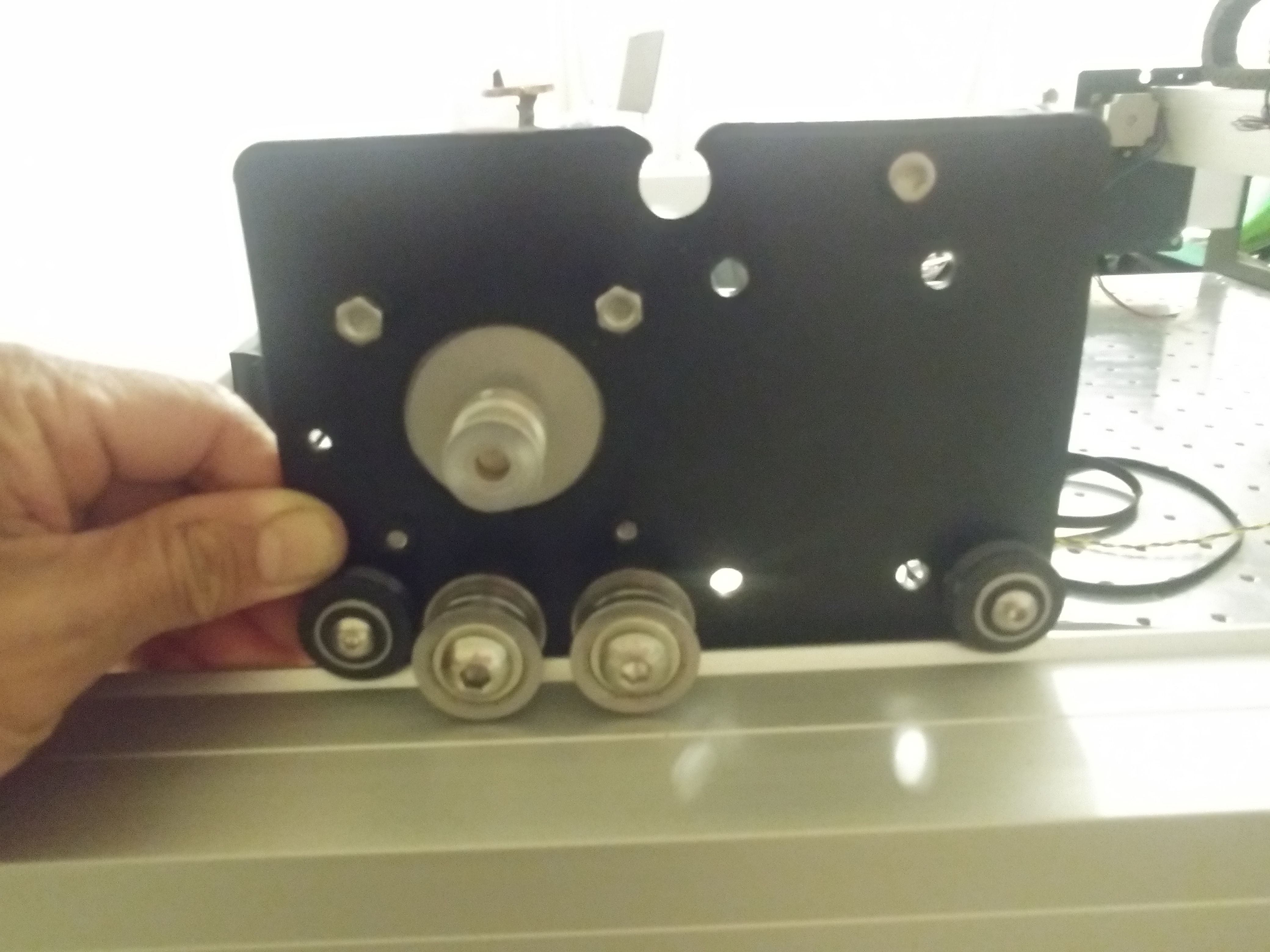
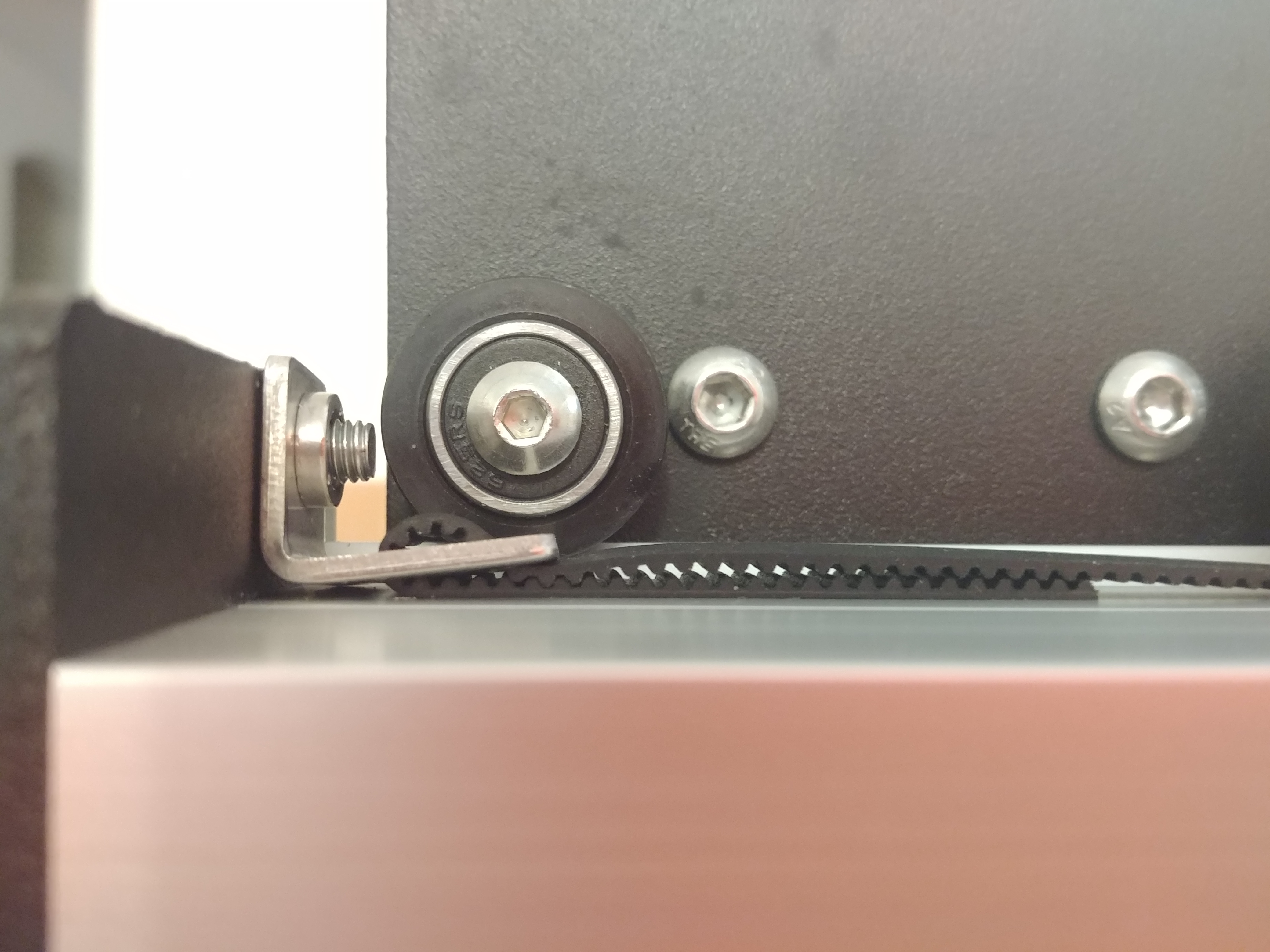
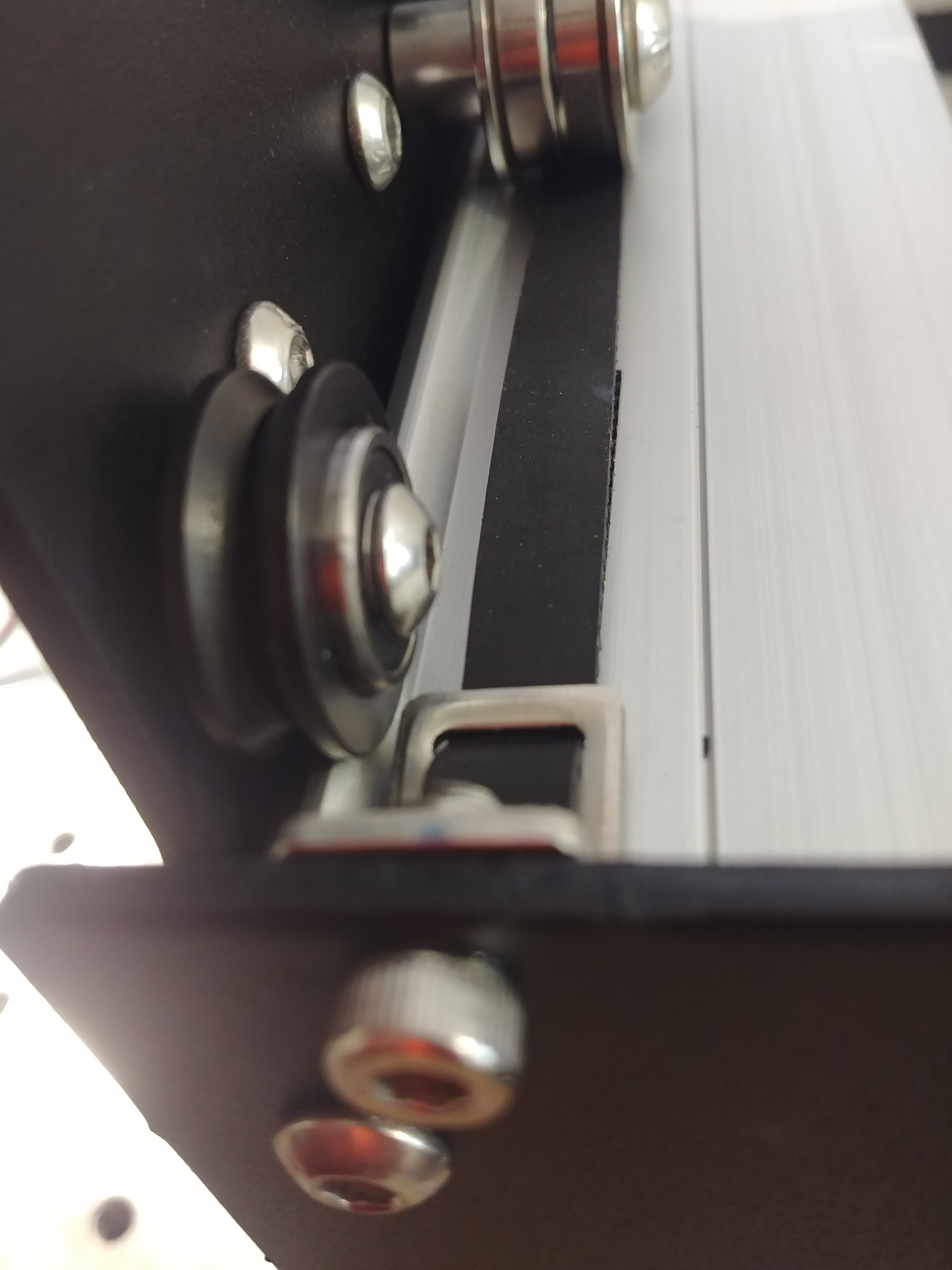
Additional upward and downward force will reveal the play/gap between the V-wheel and V-guide.

Tighten the V-wheel hex bolt. Note that by tightenning the hex bolt the adjustment will change to tighter or loose fit. Verify for any up and down play on both corners.

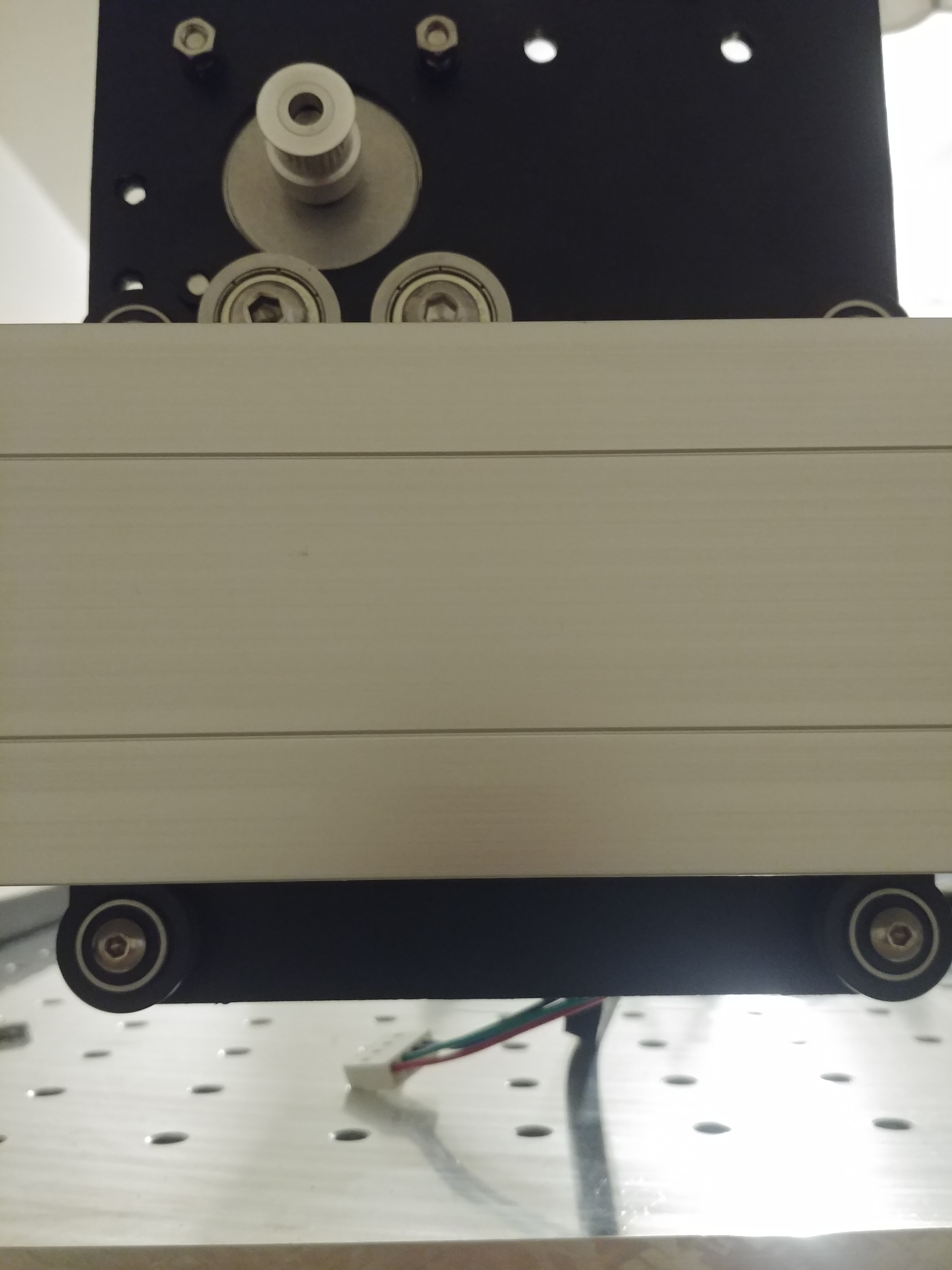
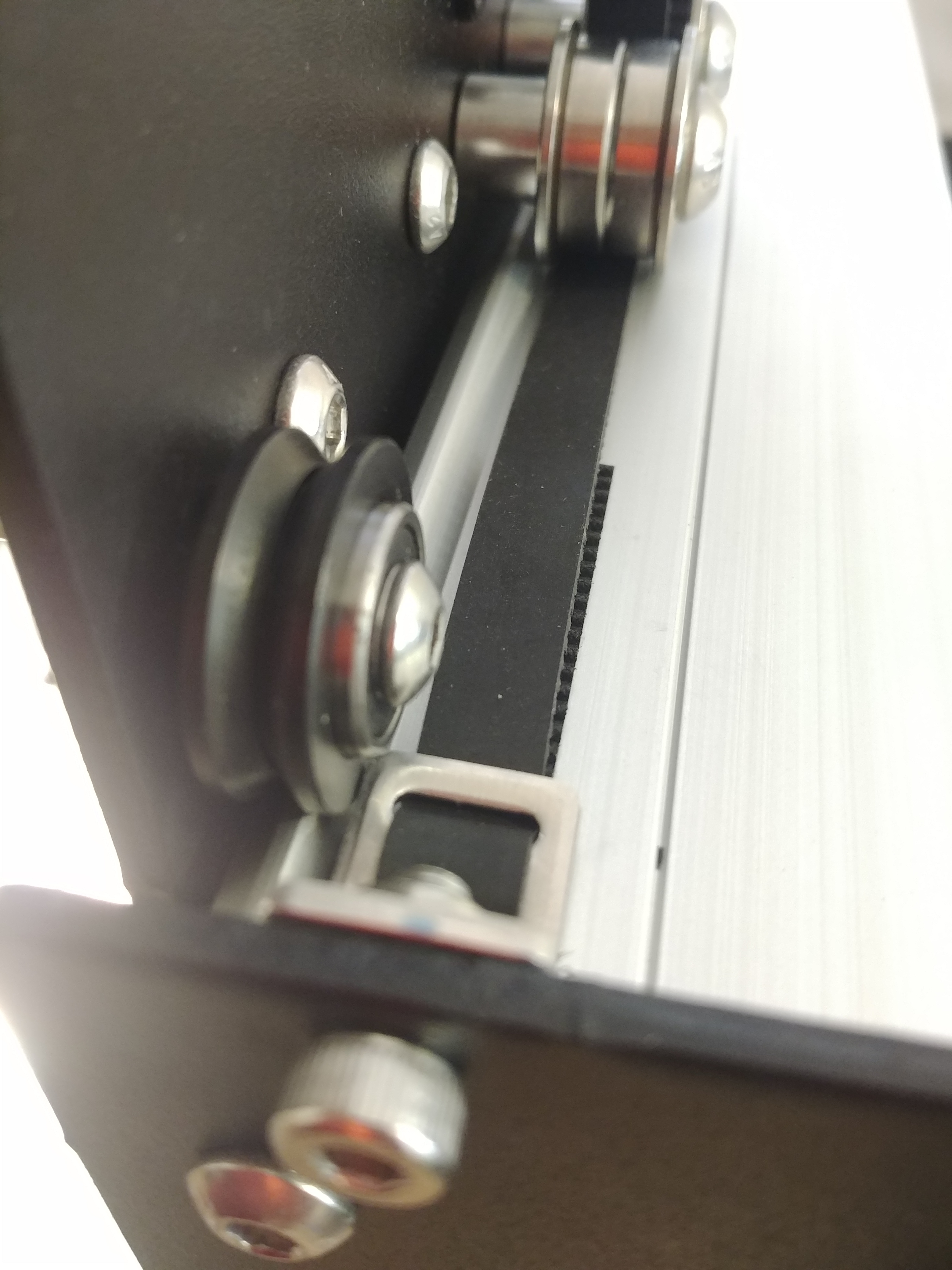
With your fingers in this position, move the carriage plate back and forth. Feel for any lateral play. Do the same for the opposite end. There should be none. If there is, check and see if the hex bolt is tightened. Also check if there is up and down play. Adjust as necessary.

This pressure, back and forth seats the V-wheel onto the V-guides and checks for additional minute play. I discovered this verification check by accident when I noticed a bump while traversing the carriage along the rails. When I applied this back and forth motion I noted additional play. Readjusted both V-wheels and the bump went away.
.
.
.
.
V-wheel out of round check

Rotate each V-wheel. You should feel a drag or slippage. The carriage will feel like it wants to traverse along the rail. Continue rotating the V-wheels while restraining the carriage and check for any flat spots. It should feel smooth. You will know if there is an issue with the V-wheel, because there will be a feeling of a detent. I found 1 V-wheel on my carriage that had a dead or flat spot.
.
.
.
.
V-wheel Slippage/Friction Adjustment.

This is difficult to describe how to go about since it is all about feel. For those that understand how a feeler gage works this the same principle.

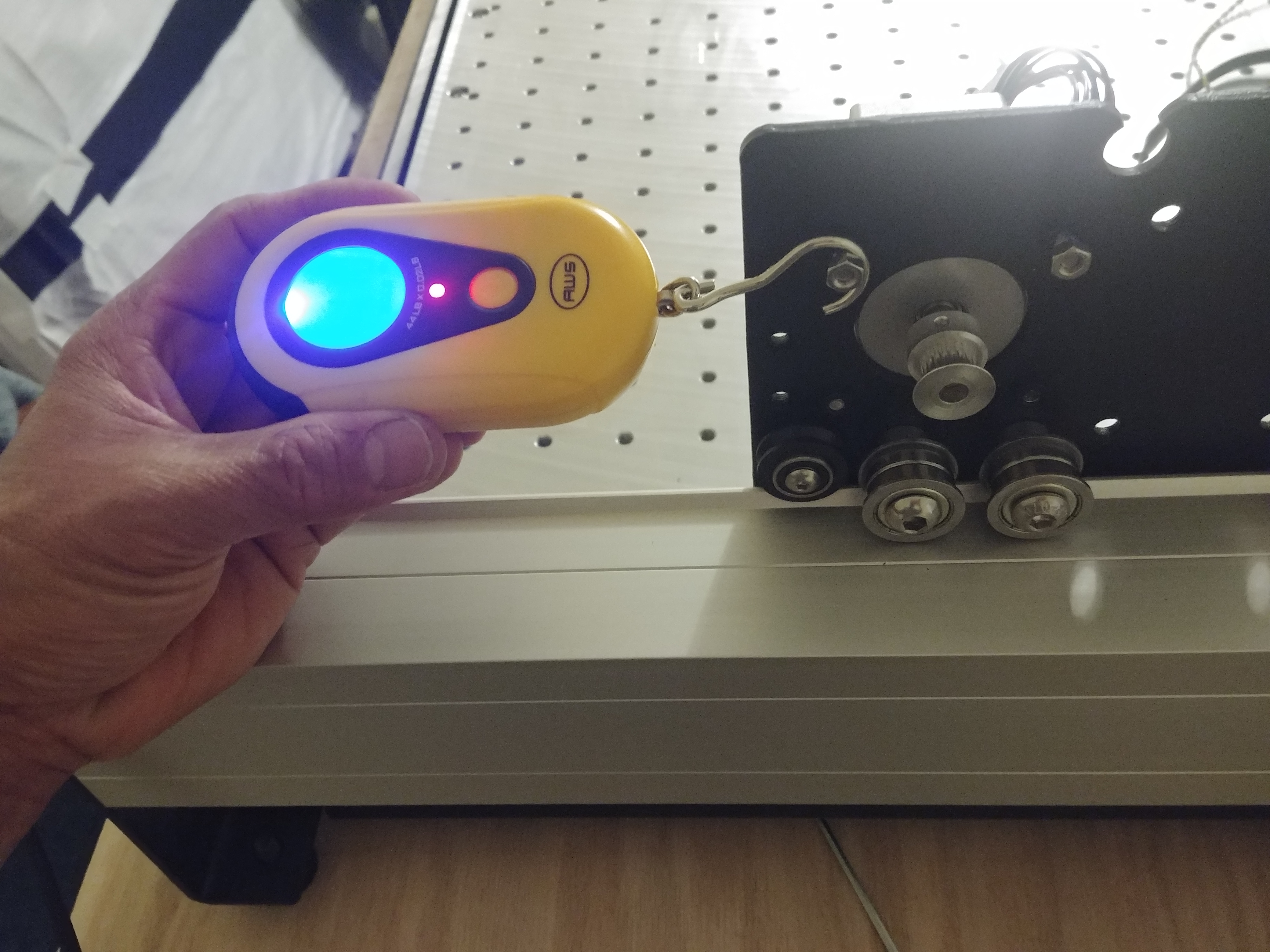
However, I will use a fish scale to provide you with a visual. There are no specs for this procedure, just know that too much load on the bearings will create that bump feeling and may damage the inner walls of the V-wheel bearing (notchy).

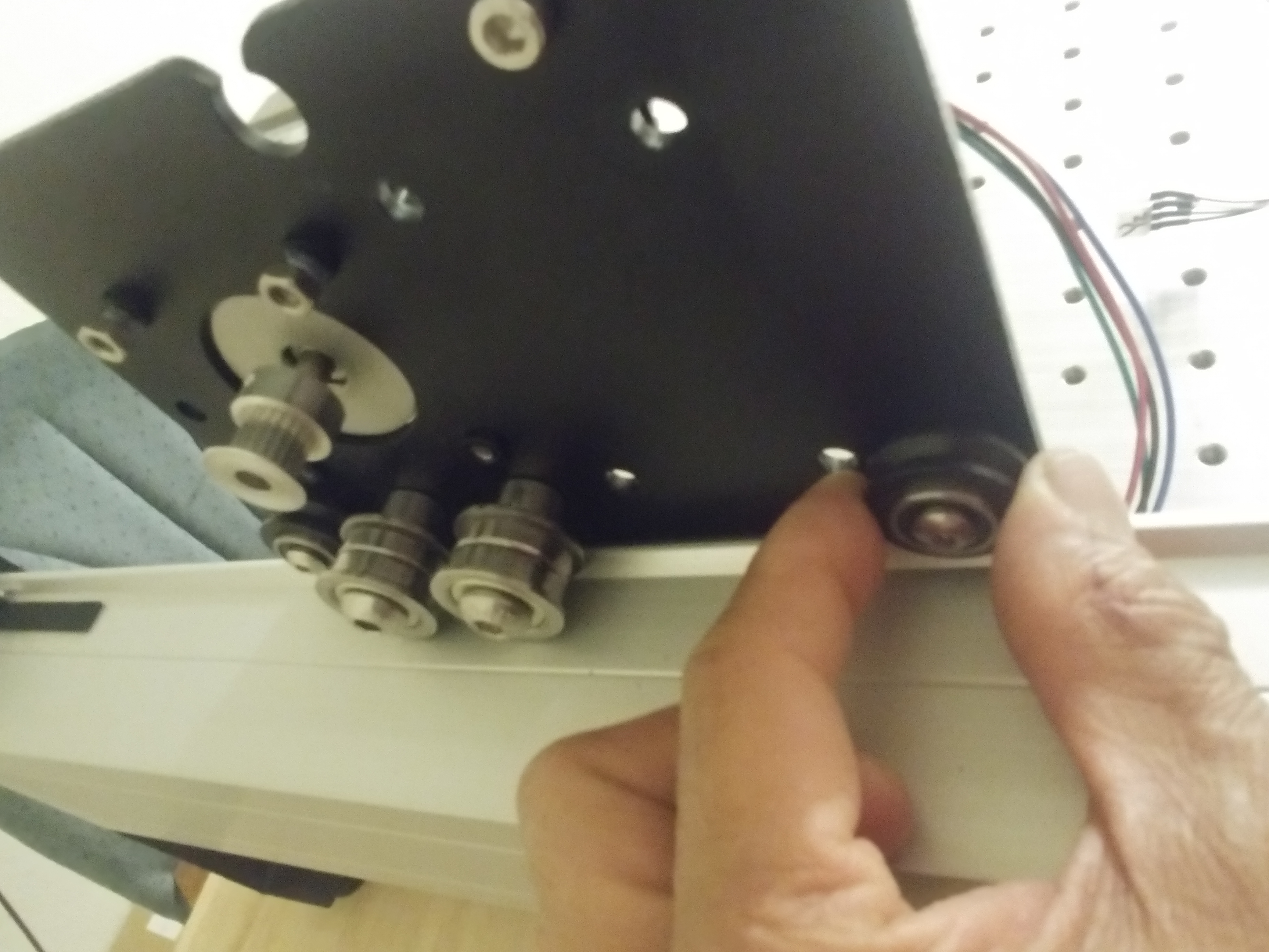
Rotate the lower V-wheel while restraining the carriage from moving. Note the pressure of rotation and the friction from the V-wheel slipping. Verify that this friction and rotation force required to rotate the V-wheel are the same for both V-wheels.

Using a fish scale, although difficult to standardize, I am able to exert a force of approximately 1.2 lb on the fish scale. I have found that the fish scale is not necessary, but it gives you and ideal for “visual to feel” when determining how much drag or friction it takes for the V-wheels to slip while restrained. After several V-wheel adjustments the feel will become second nature and you can make both V-wheels with equal slippage.

The objective is to know the right feel of friction while rotating the lower V-wheels and that both V-wheels feel the same amount of resistance/drag.

The key to the correct adjustment to get that resistance/ drag is creeping up on the up/down play and knowing went to back off in adjusting the eccentric nut. If unsure back off the eccentric nut, tighten the V-wheel hex bolt, check for play repeat as necessary.

After all is said and done, you can remove the hex bolt and add loc-tight. Or add loc-tight during the adjustment process and be done.

When you are satisfied with the adjustment, move the carriage along the entire rail and take note of any bumps or noise.

You can now assemble the carriage to its respective rails.

1 Like

This is massive and it seems like some may find it helpful. Thanks for contributing!

Online Assembly Instructions, Step 7, Cleaning it up … Securing The X-Axis Drag Chain.

Here’s where I ran into issues. The instructions states to secure the drag chain with VHB tape approximately 3 inches from the Left Y axis carriage.

As you can see from the below pic, the drag chain is preventing the XZ carriage from contacting the Right Y axis carriage.

If I were to do this, my preferred method would be to set the XZ carriage so that it is contacting the Right Y axis carriage. Then slide the drag chain towards the Right Y axis carriage.

Mark the location of the free end of the drag chain. Apply the VHB tape at this location. This is not an approximate distance but the true distance for each setup. As you can see from the pix, my distance from the Left Y axis is at 3 13/16".

Performing the steps as described above will ensure the correct placement to secure the free end of the drag chain thus ensuring an unobstructed path for both the drag chain and the XZ carriage.

1 Like

Squaring Obstruction:

Another reason why I prefer to Square the Shapeoko 3 XXL before I install the drive belts.

As you can see in the pic below, without the drive belt, there is no gap between the drive belt L bracket and the rails.

With the drive belt on the L bracket and fastenened to the front/rear frames, the drive belt is compressed between the L bracket and the rails.

This downward force is acting upon the rails. By loosening the 4 button hex bolts creates issues when trying to square up the frames and possibly cross thread the screw threads in the aluminum rails. This can be felt when tightening the hex bolts as a coarse feeling while turnning the hex bolt.

1 Like

V-wheels and Drive Belt “L” bracket obstruction.

When fastenning the drive belt L bracket to the front or rear frames, verify that the drive belt L bracket does not interfere with the V-wheel at end of travel.

Note the drive belt L bracket touching the V-wheel.

Another angle …

Use an adjustable wrench to hold the drive belt L bracket in place while tightening the bolt.

Note the gap clearance between the drive belt L bracket and V-wheel.

Also, ensure that the drive belt is inline with the drive motor guide pulleys.

Giban do you reside in Guam?

Not anymore. Left the Island in April 2000 and now residing in Tucson Az.

Do we know each other?

This topic was automatically closed 30 days after the last reply. New replies are no longer allowed.